
Excalibur 6000 user guide
How to use this guide
Scroll down to view the guide.
You can expand and collapse sections using the + and – icons.
View PDF version >
Other support resources
Register your cutter to activate your guarantee >
Visit Keencut support centre >
Visit user forum >
Installation video >
Contact Keencut >
This User Guide for the Excalibur 6000 gives advice on cutting techniques, care and maintenance of your machine.
Before using your machine make sure that you have installed and calibrated it correctly. Full details are in the Installation Manual.
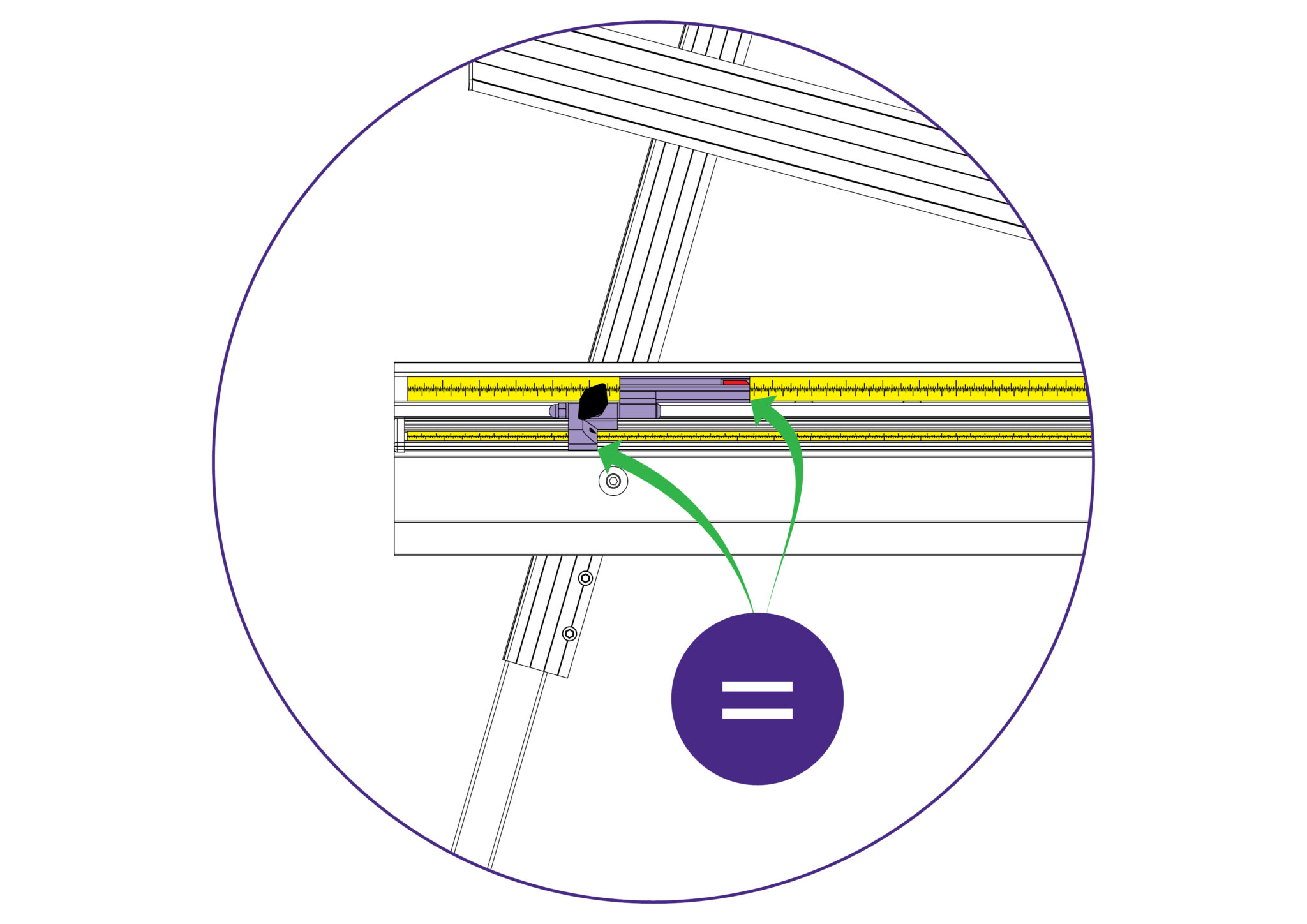
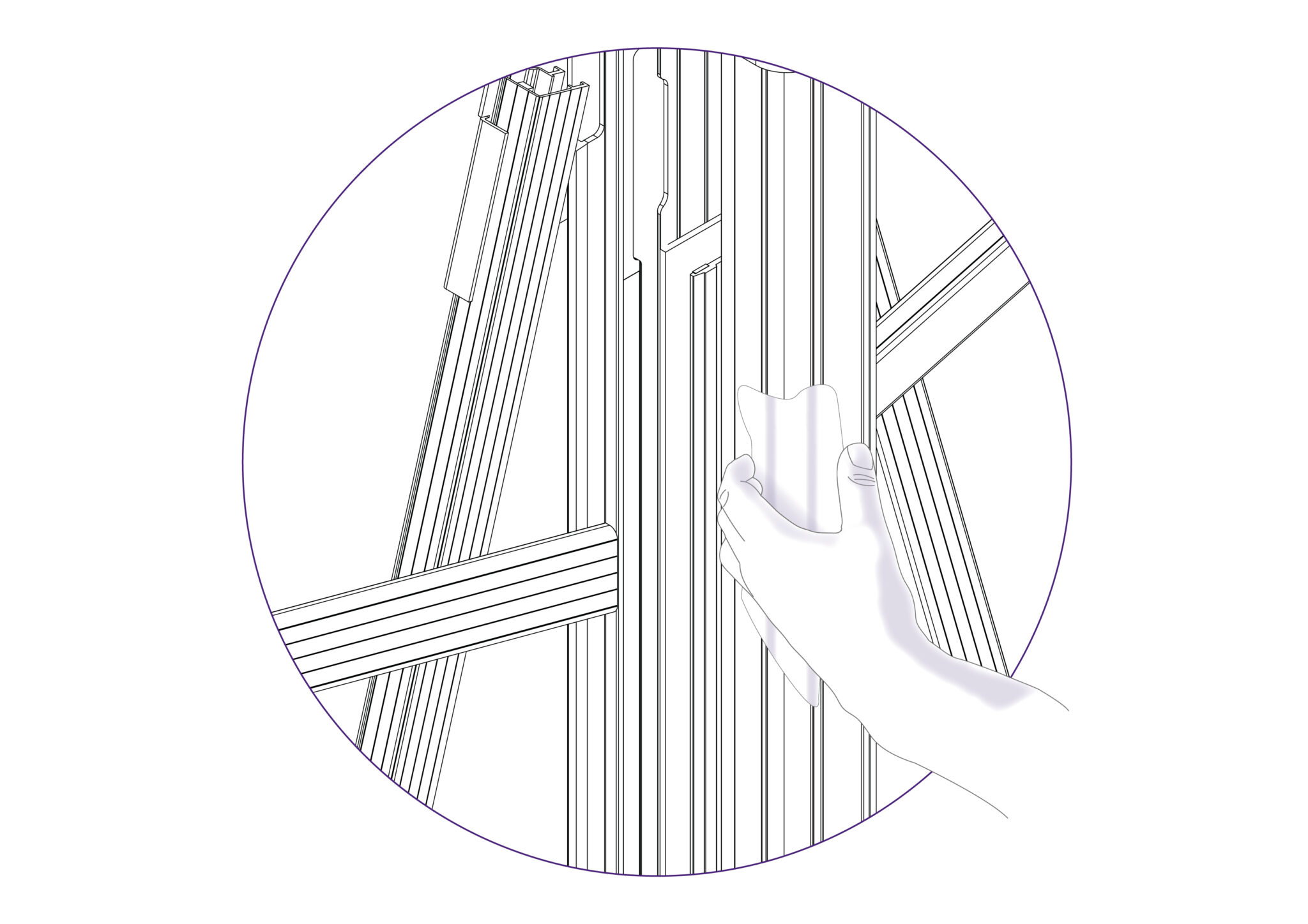
The right and left hand measuring stops enables the operator to slide in and position the materials to be cut at a set length, as decided by the fixed position of the stop.
As seen in the picture, the edges (with the arrows pointed at them) indicate the exact same length at which the material will be pushed up against the measuring stop. Ensure that both scales on the machine are calibrated as defined within the “Calibrating the squaring arm scales >” and “Calibrating the Easy Measuring Scale >” sections of the instruction manual.
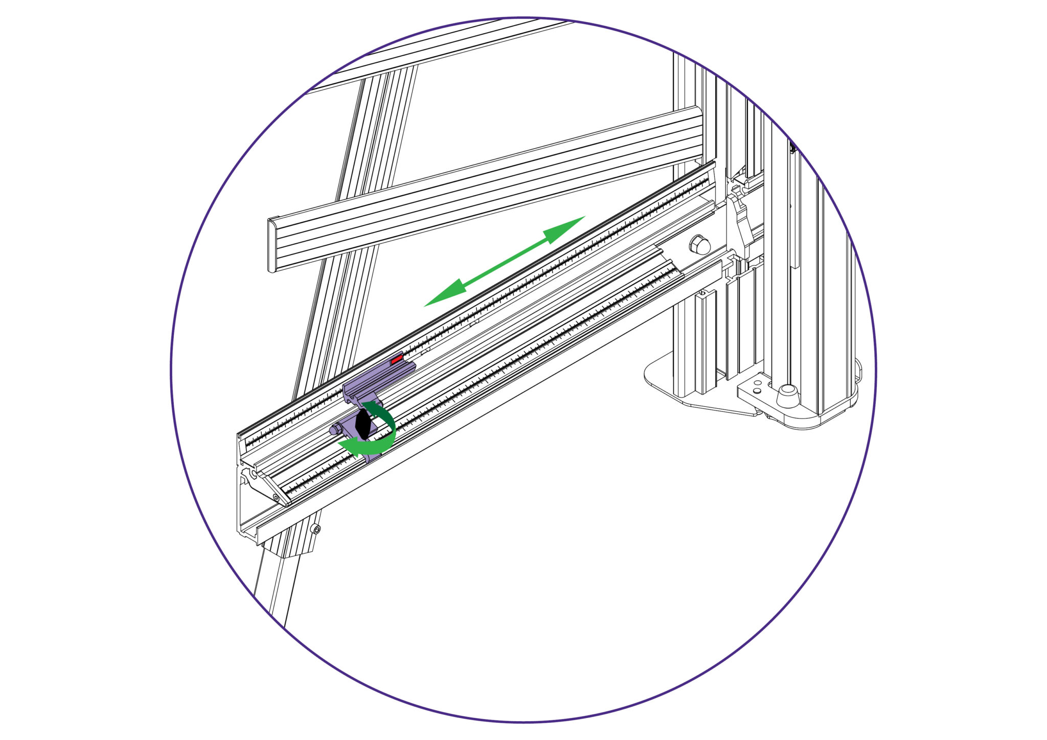
Rotate the black knob on the measuring stop counter-clockwise to loosen the stop and move it to the desired length measurement on either scale.
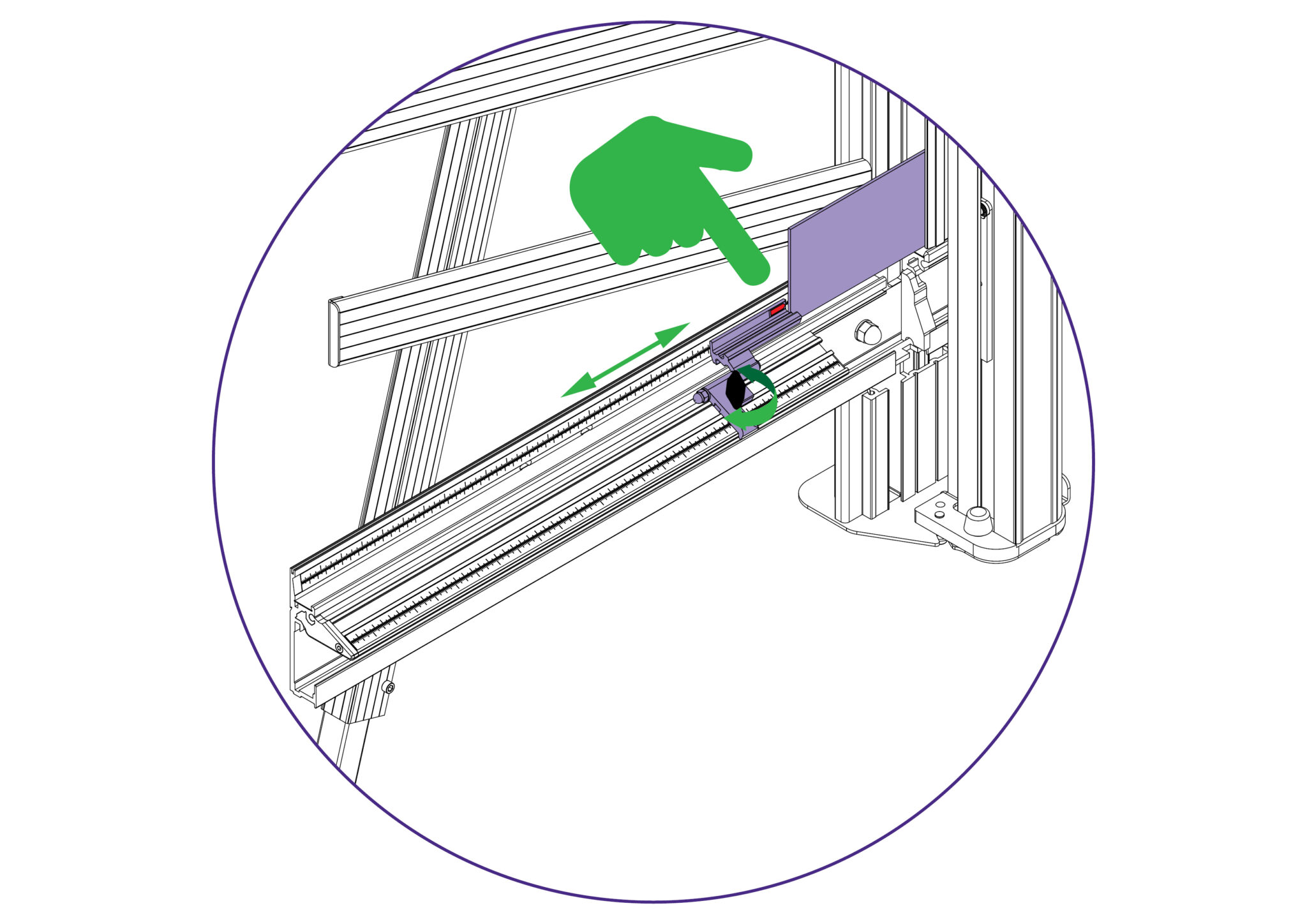
Rotate the black knob on the measuring stop clockwise to fasten the stop and set the material (to be cut) against the measuring stop.
The clamping system enables the operator to control the grip pressure by means of an integral friction brake, that maintains the clamping force at the pressure applied by the operating lever.
Soft materials can be held firmly without sustaining damage and solid materials are held rigidly without movement.
By following the guidelines below it will help you to get the most from the machine.
The Excalibur 6000 is fitted with two Cutting Heads running on two vertical stainless steel tracks. The lower or multi-tool cutter head has a rotating turret arrangement where any one of the three cutting tools can be selected:
1) Cutting Blade – Using a standard Medium Duty utility blade (not Heavy Duty – they will not fit) to cut PVC Foamboards like Forex®, corrugated plastic such as Correx®, card, matboard and many other types of rigid boards up to 13mm (1/2″) thick.
2) Scoring Blade – An inversely positioned Medium Duty utility blade is used to score the surface of any brittle plastics including Acrylic’s such as Perspex® and Plexiglass. Once scored the plastic sheet is removed from the machine and ‘snapped’ along the score line. Any thickness (up to 13mm 1/2″) can be scored but tests should be carried out on a sample of the sheet to ensure it does ‘snap’ and to an acceptable quality (remember to use hand and face protection when doing this).
3) Glass Cutting – A high quality tungsten carbide wheel is used to score glass.
The top carriage in a standard machine is fitted with the TW (Twin Wheel) cutter for use with rigid boards such as MDF, hardboards, and some mountboards up to 4mm. Refer to Using the twin wheel cutter > or Changing the twin wheel cutter > for more details.
The cutting wheels are made from high grade tool steel and are heat treated to give a long life but this is dependent upon daily use and the materials being cut.
The signs of the wheels wearing out are:
1) A rough finish predominately on the right hand side of the cut, with flaking on materials such as MDF.
2) The bottom of the cut bursting out rather than being cut neatly.
3) The board trying to turn under the clamp when being cut (also check the clamp pressure).
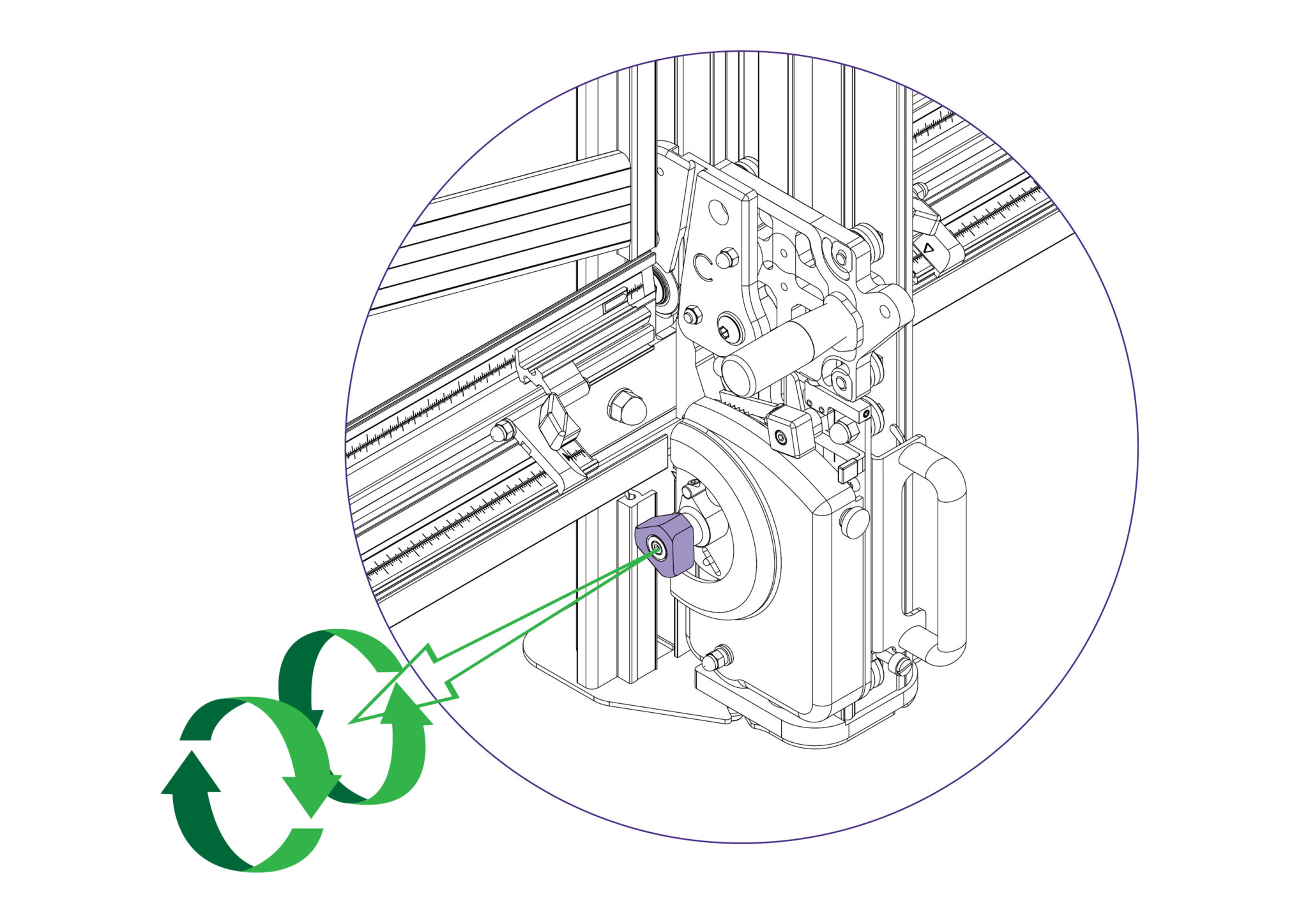
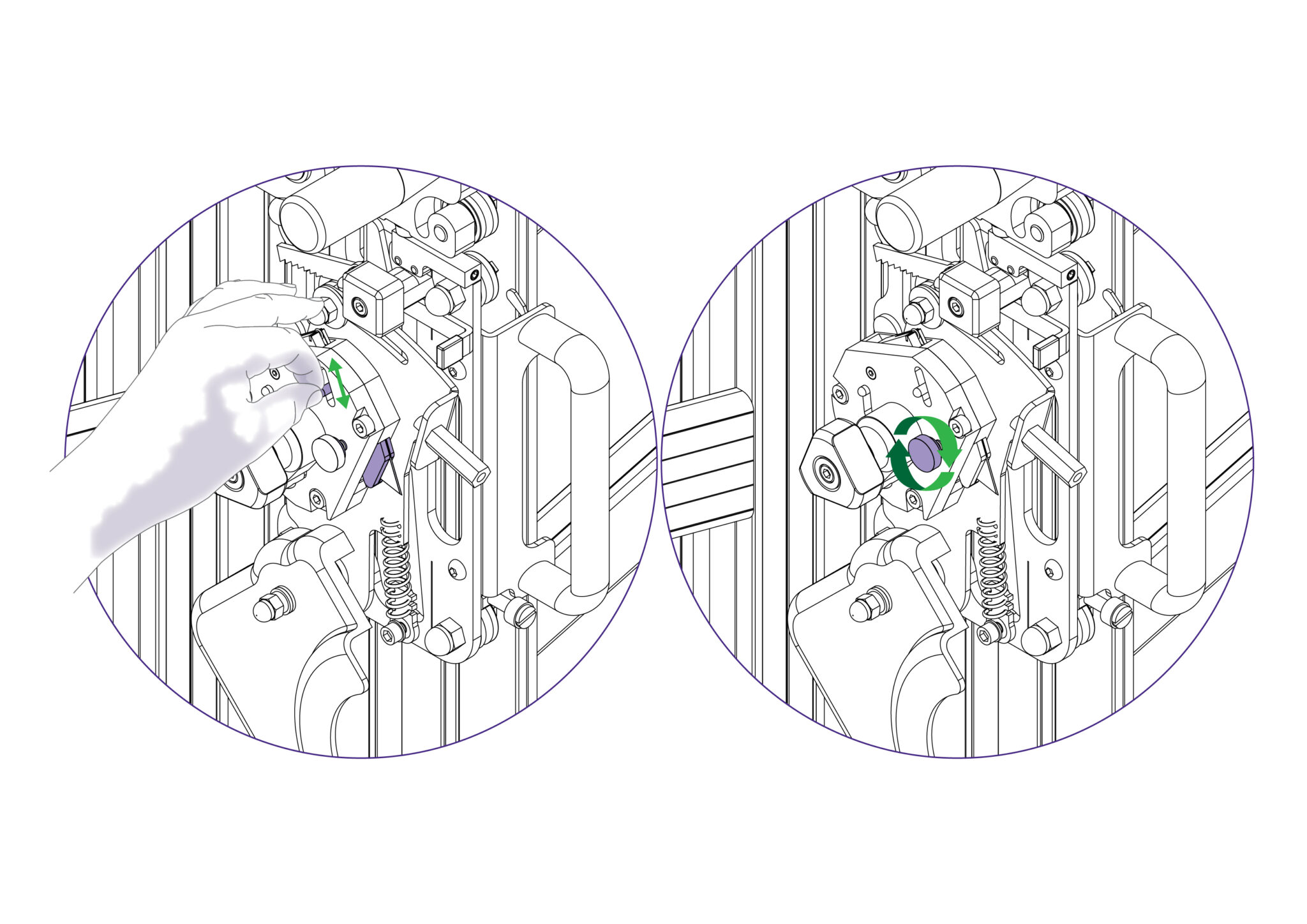
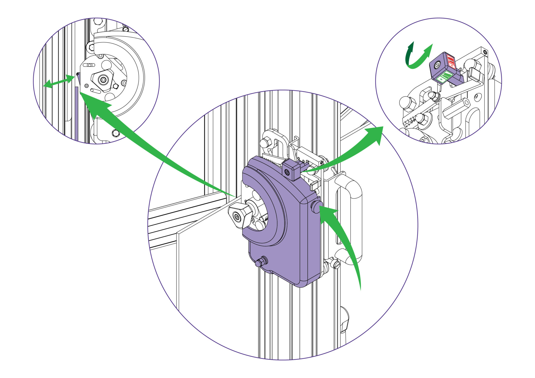
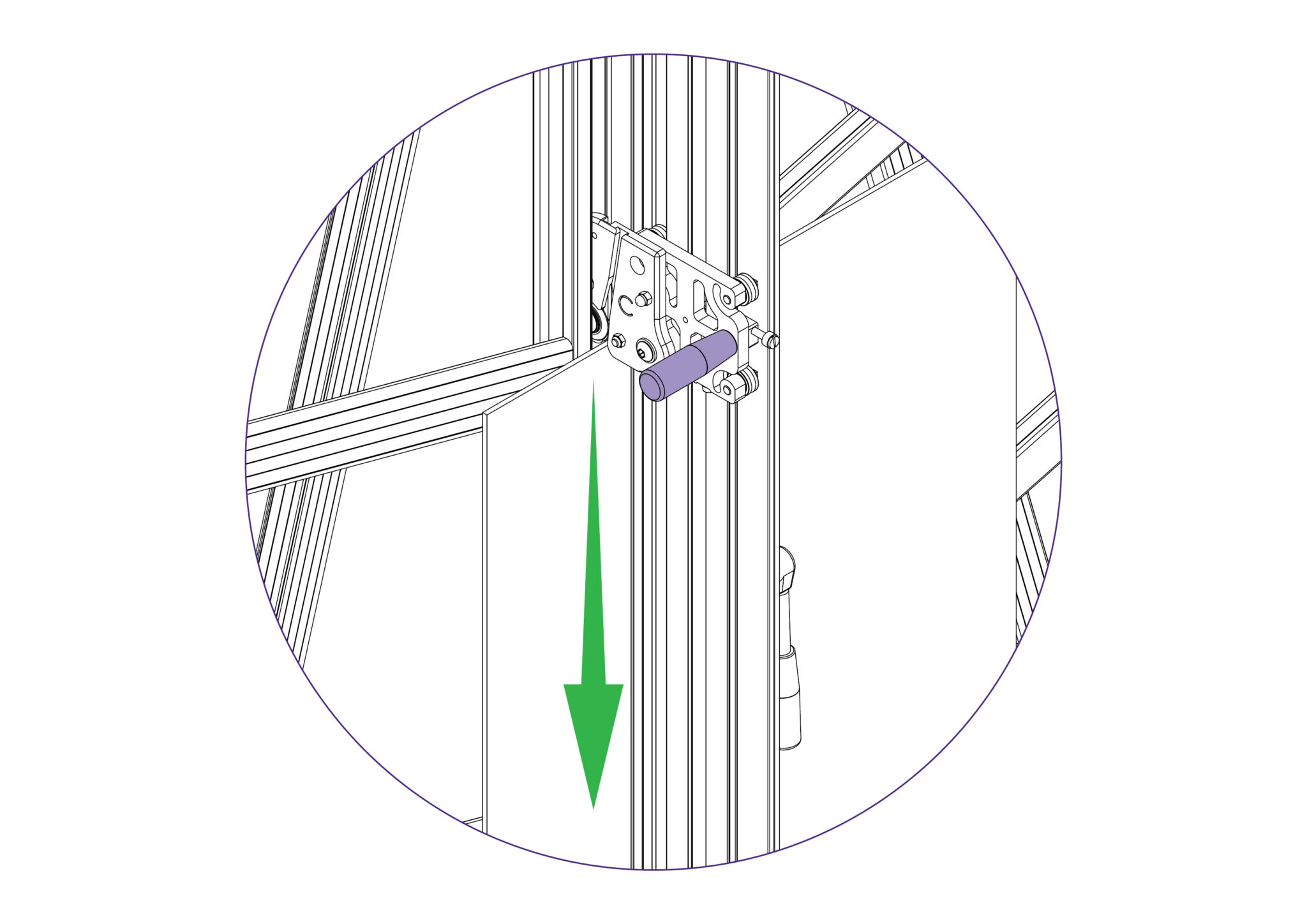
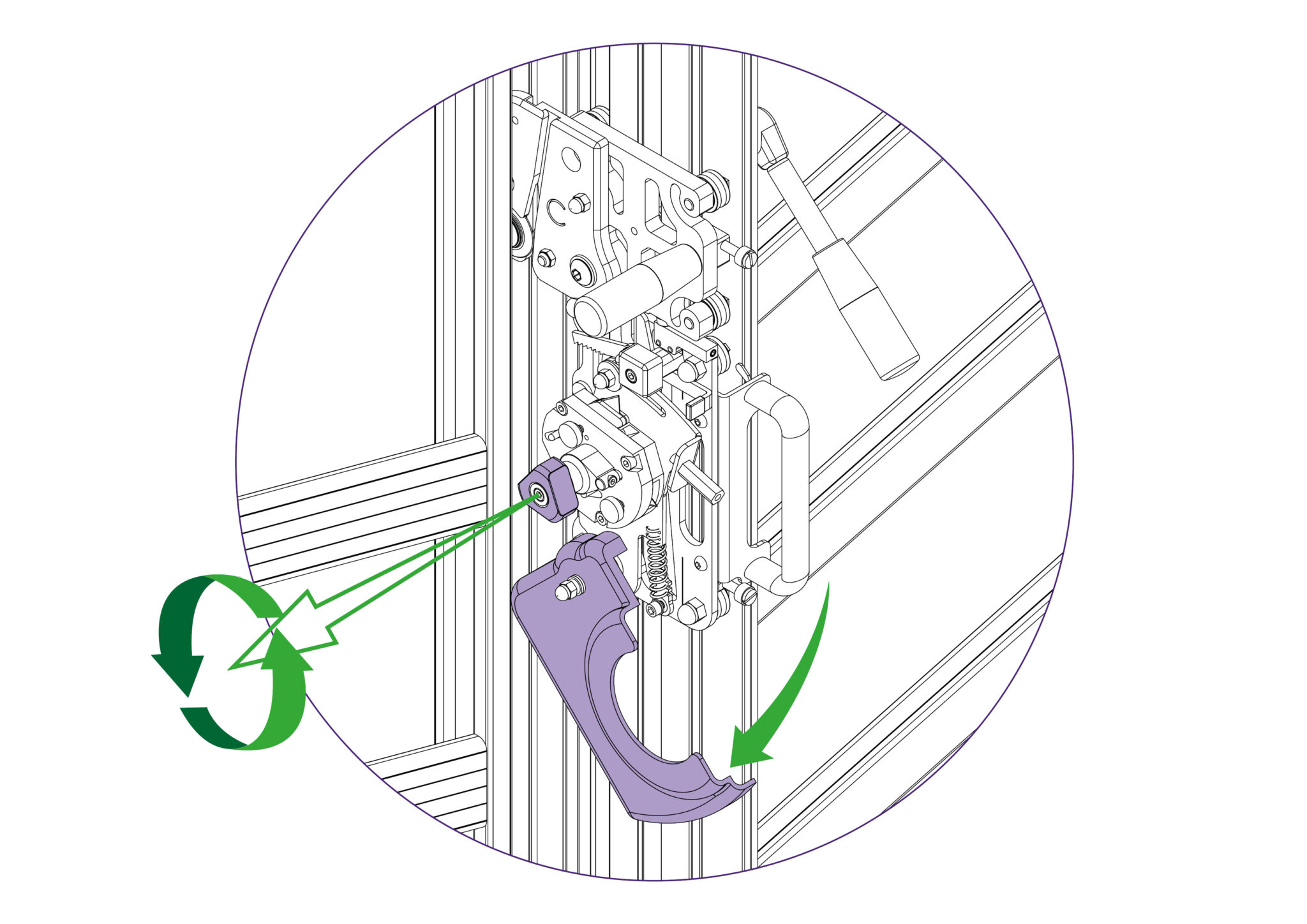
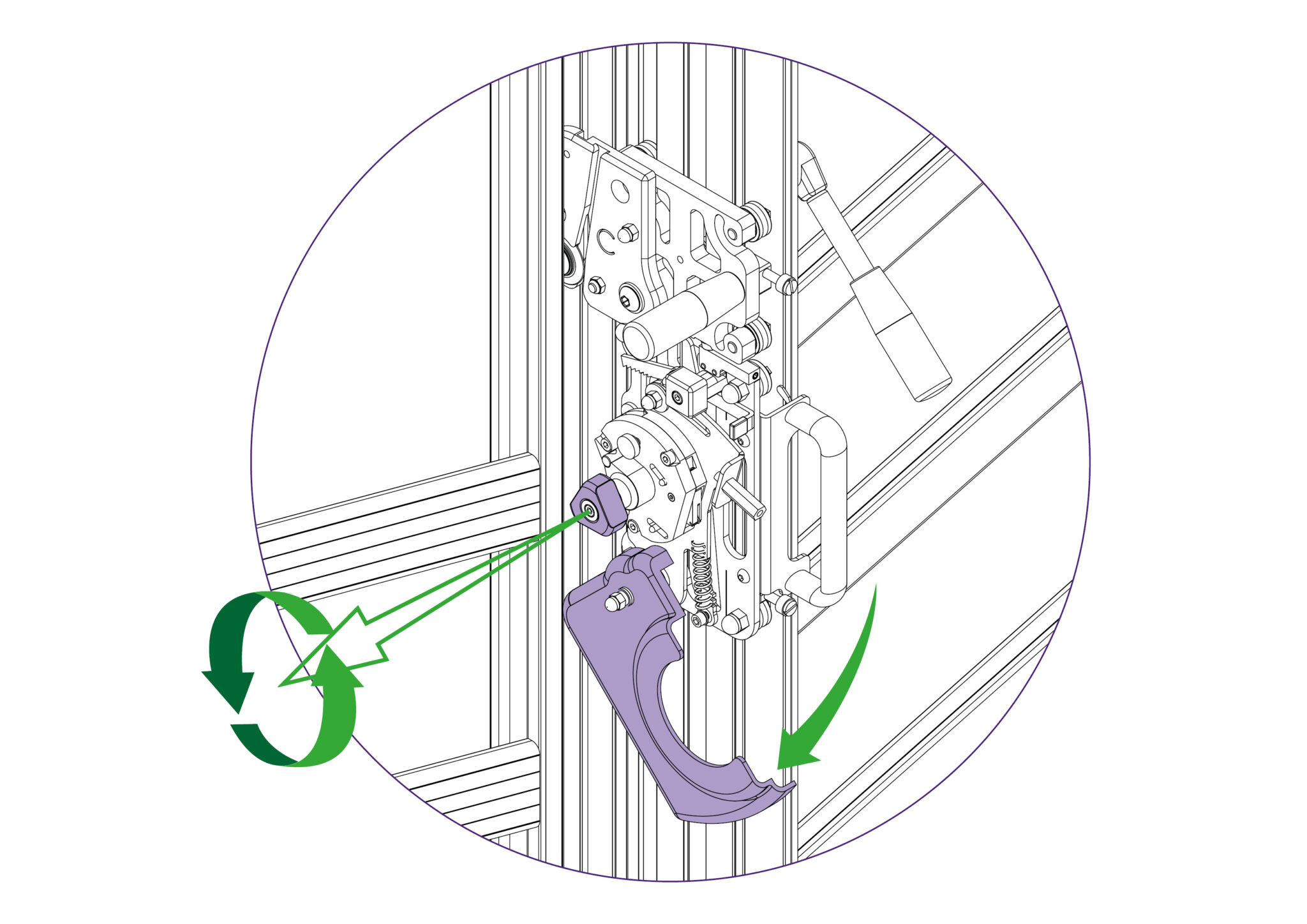
To select a different cutter pull the turret handle out to the left about 6mm (1/4”) and rotate in either direction, the turret will click into the correct position for the cutter indicated.
The indicator label on the turret handle, that faces the user, shows which cutter is active.
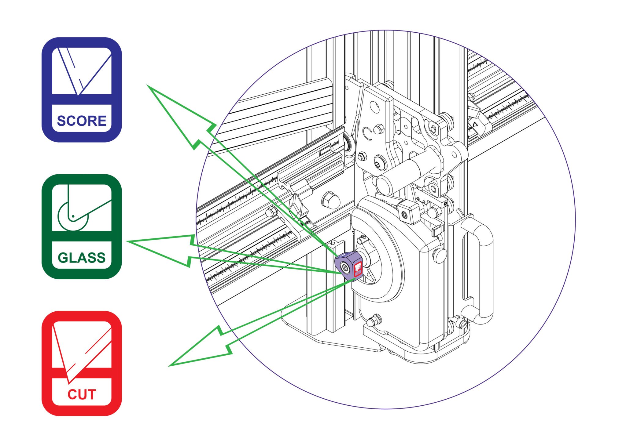
A unique feature of the Excalibur is the ‘ratchet latch’. This enables thick dense materials such as PVC foam board to be cut easily in stages. Count the number of ‘clicks’ to position the blade just below the surface of the material to make your first cut, and then add an extra ‘click’ for the second and subsequent cuts.
As a rough guide when cutting PVC foam board:
3MM (1/8”) Initial surface cut + 1 additional cut
5MM (1/4”) Initial surface cut + 1 or 2 additional cuts
10MM (3/8”) Initial surface cut + 3 or 4 additional cuts
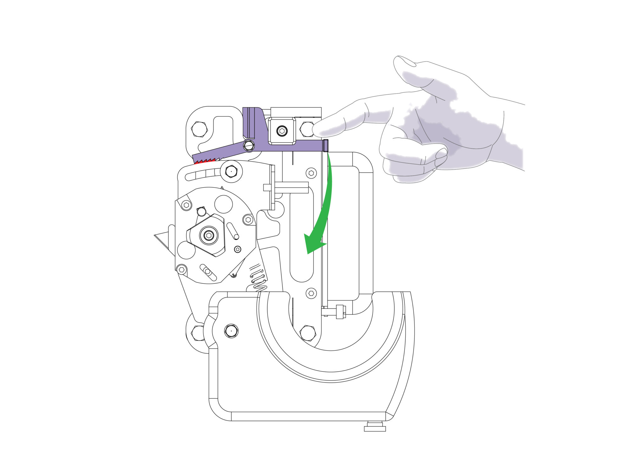
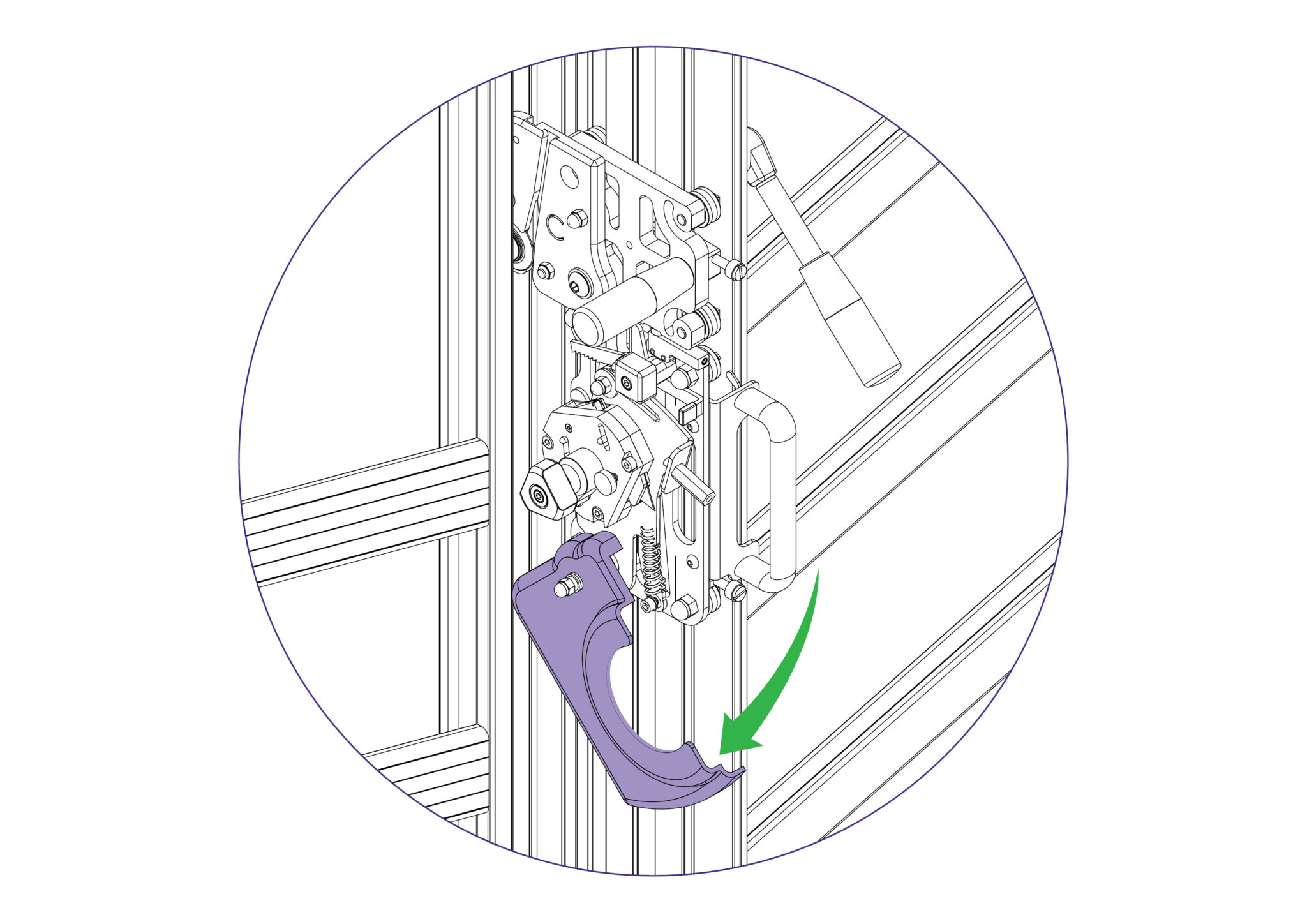
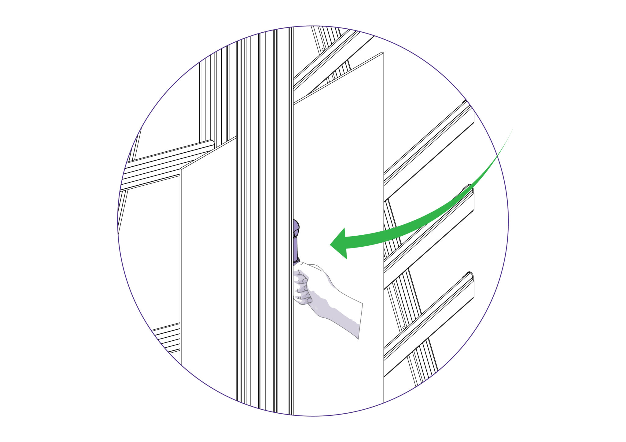
Should you engage the cutter by mistake or for any reason want to disengage the cutter without moving it to the bottom of the machine, pull down the cutter release lever.

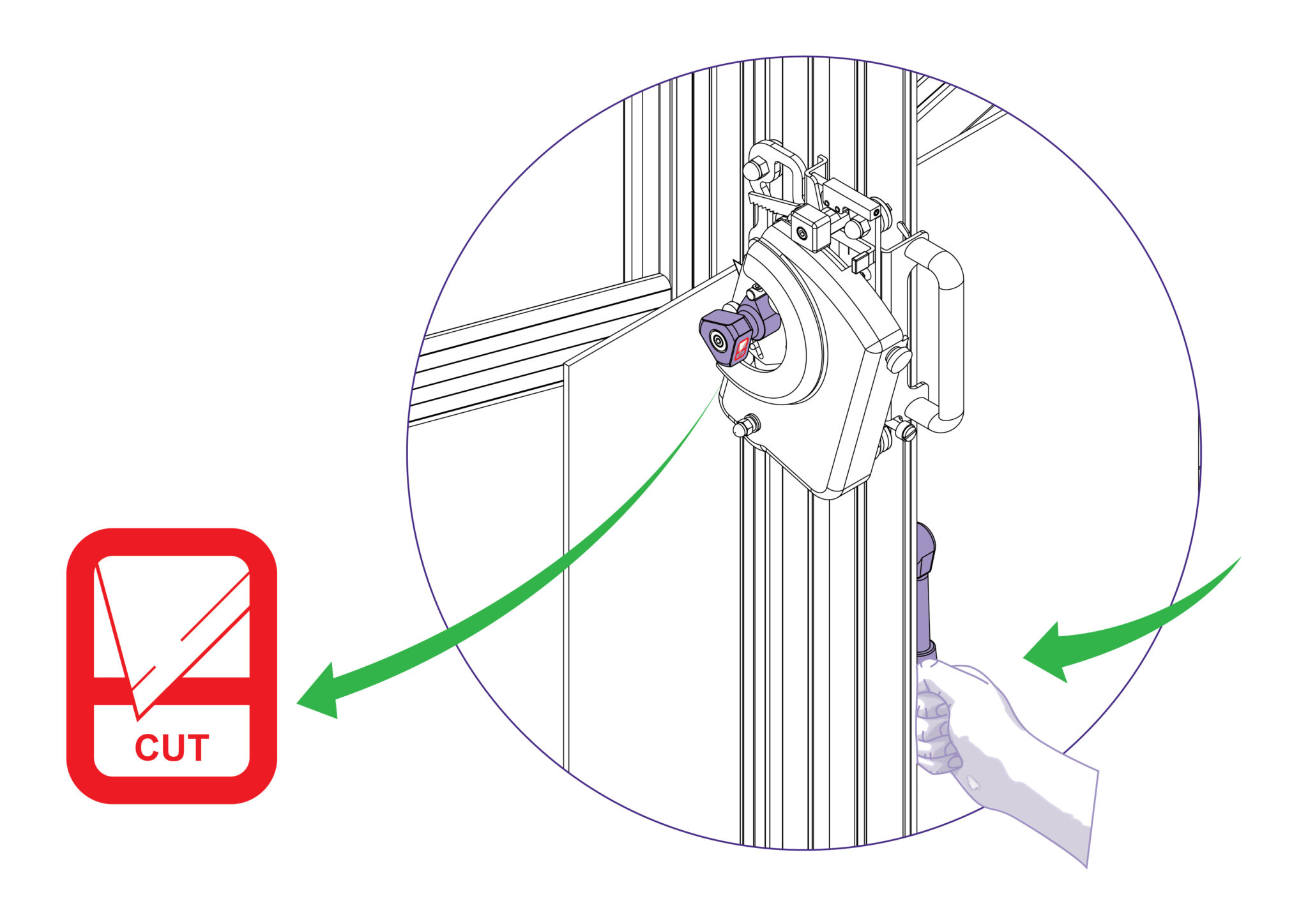
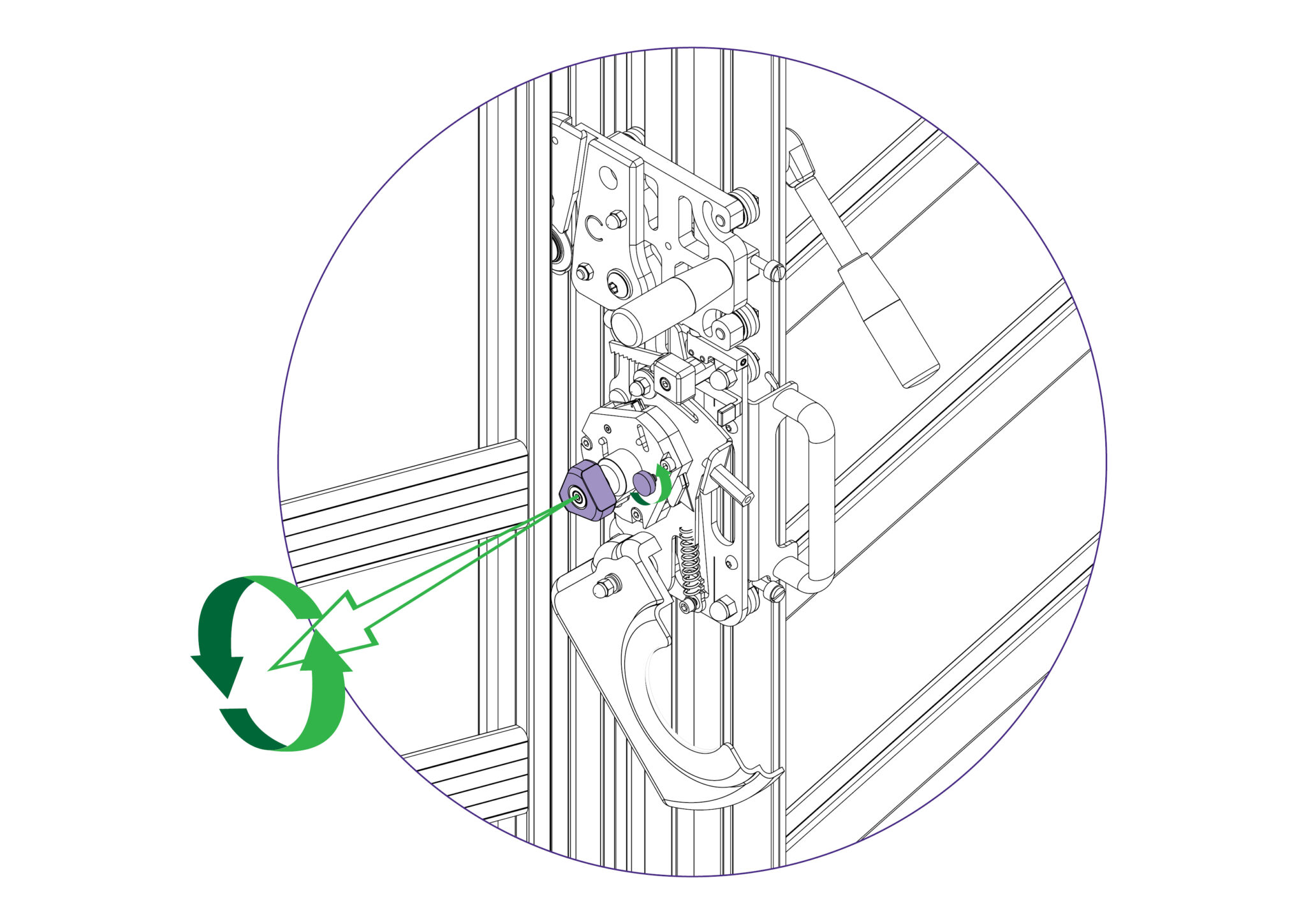
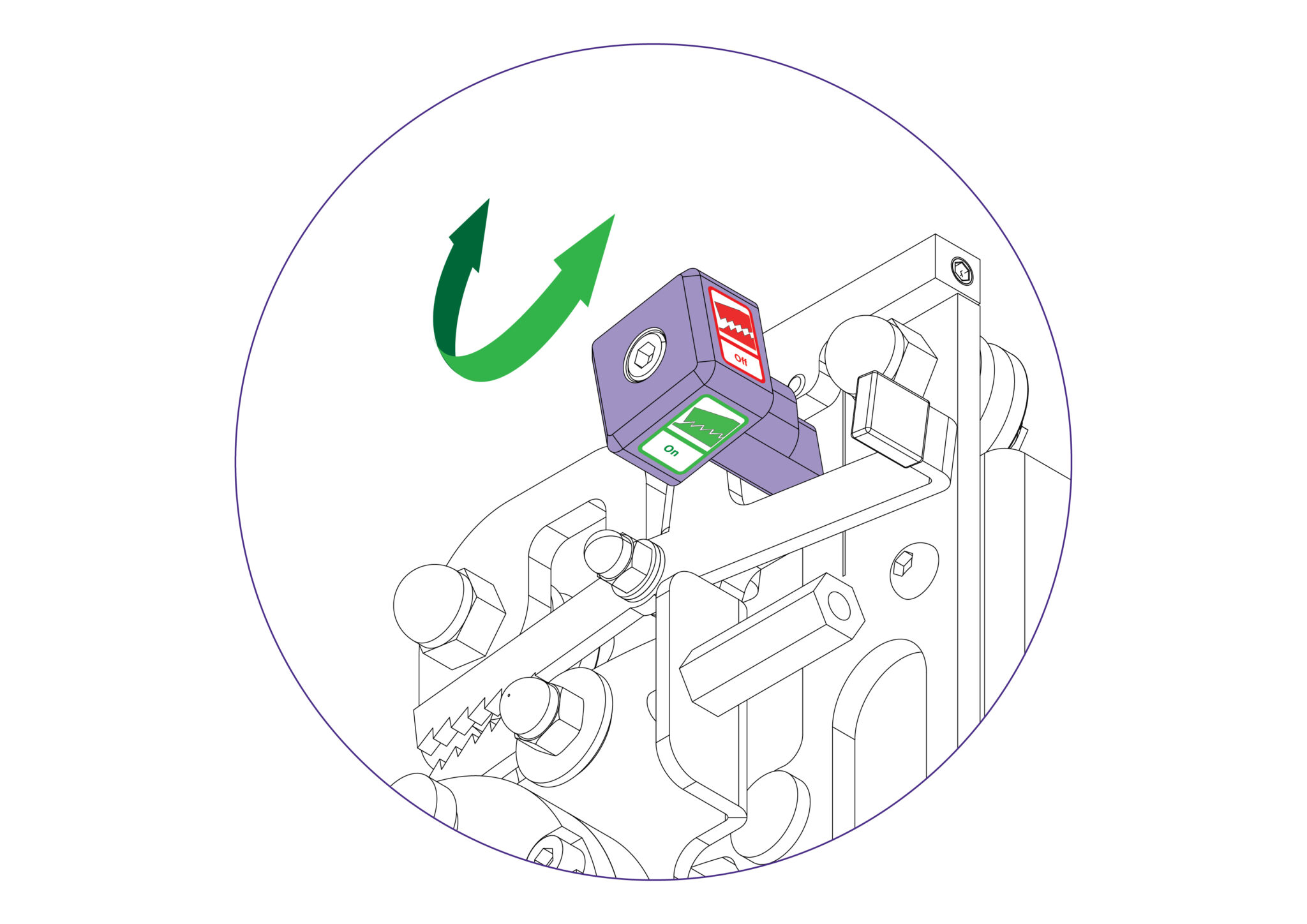
For some operations (such as scoring acrylic) the ratchet latch needs to be disengaged, so that finger pressure can be used to make the score/cut. This is done by turning the black knob with the ‘On’/’Off’ stickers such that ‘Off’ faces towards the user. To re-engage the ratchet latch, turn the black knob such that ‘On’ faces towards the user.
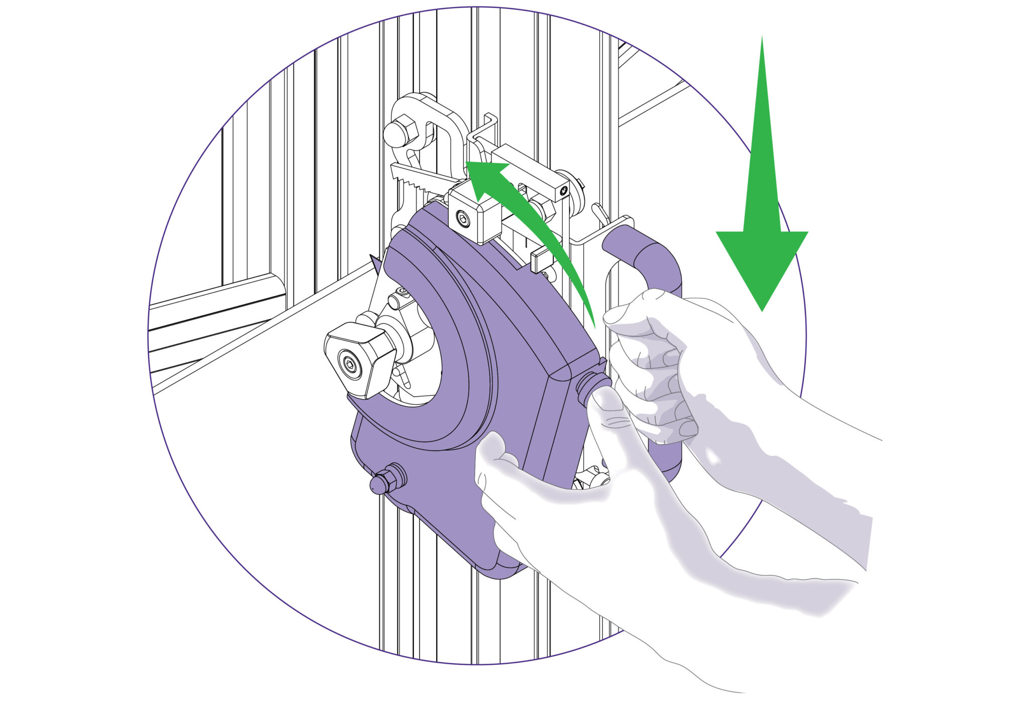
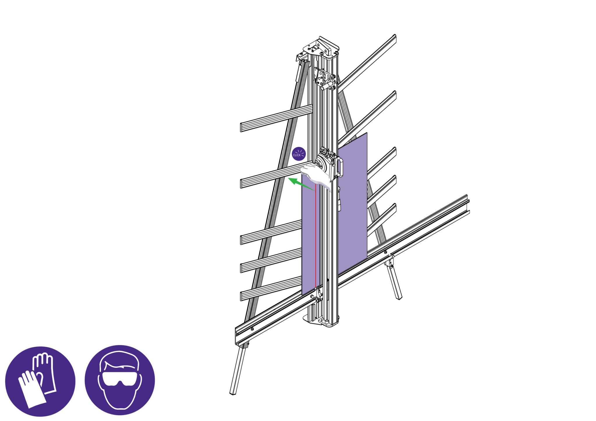
Select the cutting blade position on the turret and clamp the material in the machine.

Press to engage the cutter. Draw the cutter down to the bottom of the machine where it will disengage automatically.
The two support plates either side of the blade are designed to give maximum rigidity of the blade when cutting hard or dense materials. To adjust the support plates, swing down the cutter guard by undoing the black locking knob (on the guard) facing towards the operator.
Turn the turret ½ turn until the blade is pointing towards you. Then unlock the blade clamping screw.
The support plates can be adjusted by sliding the black pin in the slot. Move the plates to suit the material and ensure that the blade is pushed as far back as it will go. Tighten the clamping screw once the support plates are in position.
For cutting most materials the support plates can be set about 12mm (1/2”) from the blade tip
CAUTION: ALWAYS USE HAND AND EYE PROTECTION WHEN SNAPPING PLASTIC
NOTE : The scoring blade is designed to score acrylics, Plexiglas and other similar rigid plastics. Trials should be carried out on scrap materials first to ensure you obtain the required standard of cut.
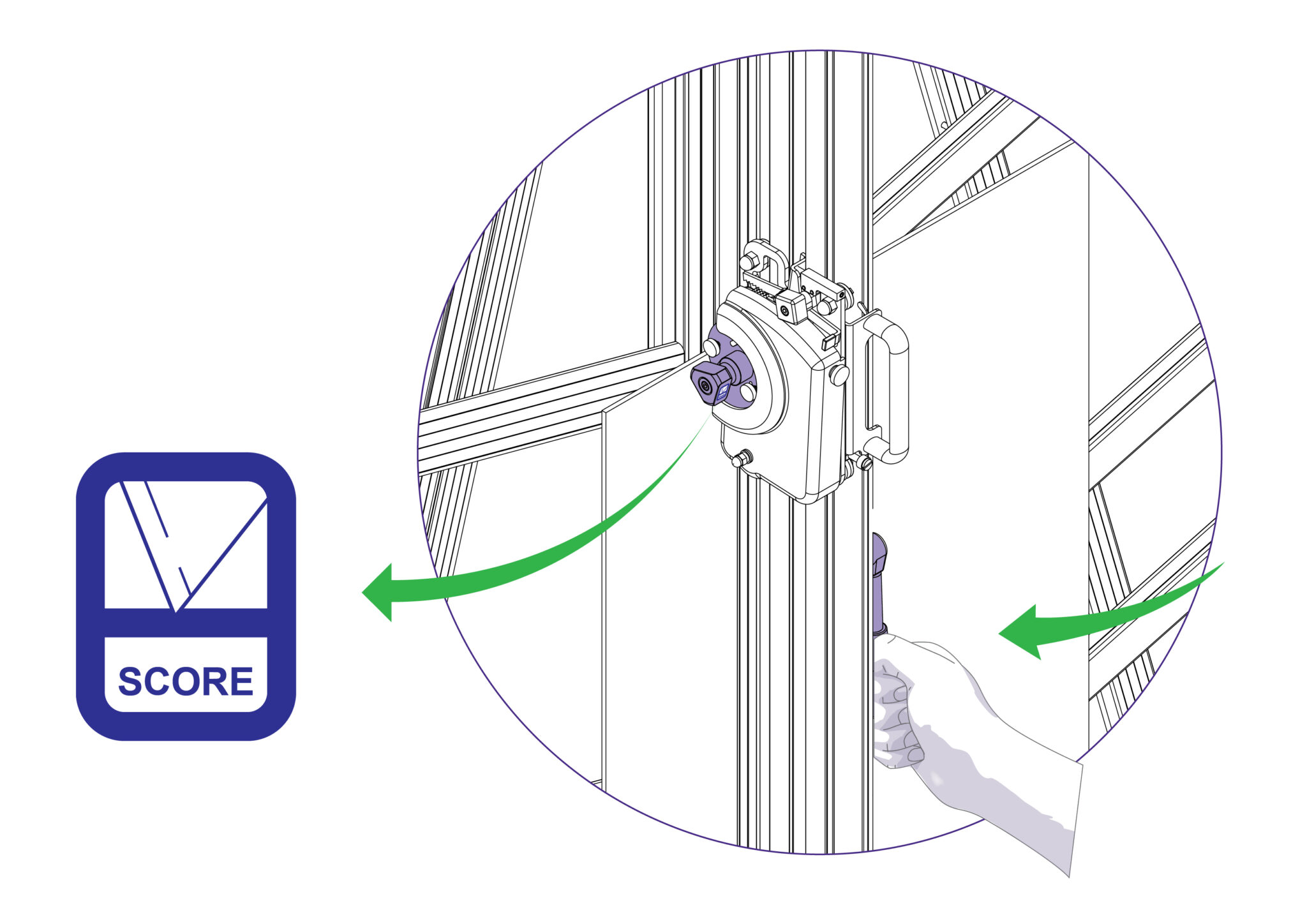
Select the scoring blade position on the turret and clamp the plastic to be scored in the machine.
Turn the ratchet’s black knob to ‘Off’ to disengage the ratchet.
Position and depress the cutting head so the blade touches the plastic at the top. Apply thumb pressure to the cutter and draw the blade down the material in one continuous motion.
Remove the plastic from the machine and snap it by hand. Ensure that the plastic is snapped in the opposite direction to which the score faces.
CAUTION: ALWAYS WEAR EYE PROTECTION AND GLOVES WHEN CUTTING GLASS
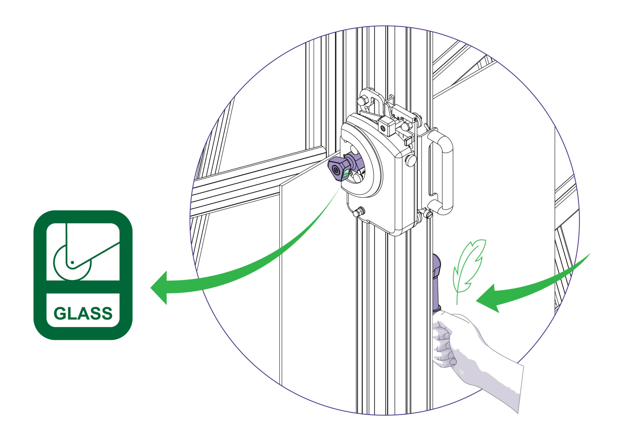
Select the glass cutting position on the turret and place the glass on the machine from the right hand side. Clamp the glass lightly in the machine.
Raise the cutting head above the top edge of the glass and press to engage the cutter fully (with the black ratchet knob switched to ‘On’). Then lower the cutting head to the top edge of the glass to be cut. The glass cutting wheel will automatically adjust itself for the thickness of the glass.
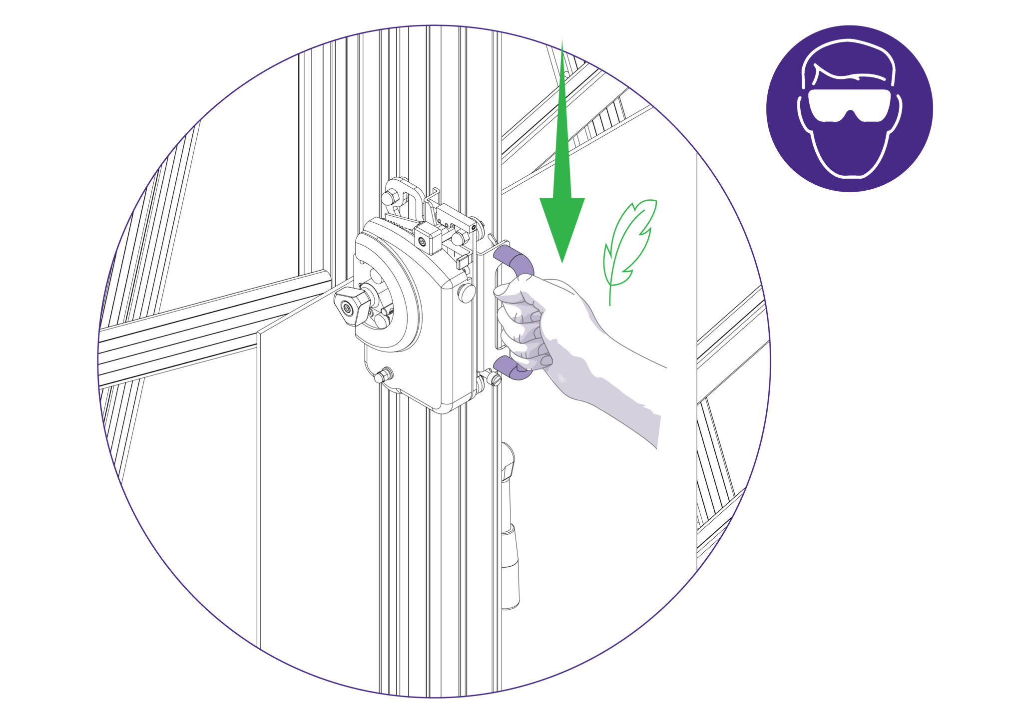
Gently draw the cutter onto the glass and down to the bottom of the machine in one gentle smooth and continuous motion where it will disengage automatically.
Check the score line, as it should be very faint and continuous.
- If the score is too deep, the line will appear white and small slithers of glass may be seen falling from it. The scoring pressure will need reducing.
- If the score is too light, the glass cutting wheel ‘skips’ and does not produce a continuous line. The scoring pressure will need increasing.
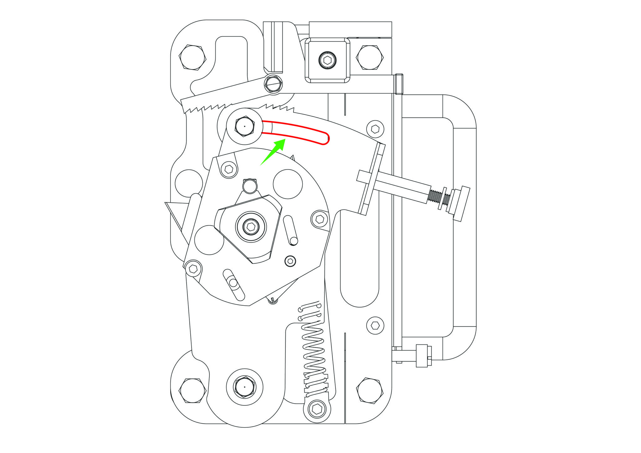
Should the score pressure require increasing or decreasing, the scoring pressure adjustment screw can be adjusted by turning it clockwise or counter-clockwise accordingly.
To break the glass, apply firm pressure to the left hand side of the score line adjacent to the top edge of the glass.
The glass should break easily, however if it resists breaking or feels springy, check the spring pressure setting.
Note: On large sheets of glass the break may only go part way down the score line, press again near the end of the
break to continue it. Never score the same line twice. We recommend the use of glass nibbling pliers for the removal of amounts less than 25mm (1”)
The twin wheel cutter is mounted on the upper cutting head and is used for cutting rigid materials such as medium density fibreboard (MDF, also known as SBS) and standard hardboard up to 3mm (1/8”) or harder materials like high density fibreboard (HDF) up to 2mm (1/16”). Many other softer boards and card can also be cut. Trials should be carried out to ensure the desired quality of cut is obtained.
Position the material in the machine and apply the clamp.
Bring the twin wheel cutter down until it makes contact with the sheet edge and stop. Take a firm grip and then push the cutter down through the material without stopping.
The cutting wheels generally last more than a year with average use, but this is dependent upon the daily usage and the material being cut.
Signs that the wheels are wearing out are:
1) A rough finish predominantly on the right hand side of the cut, with flaking on material such as MDF.
2) The bottom of the cut bursting out rather than being cut neatly.
3) The board trying to turn under the clamp when being cut (also check the clamp pressure).
Keencut machines are designed to be virtually maintenance free, however we do recommend regular cleaning
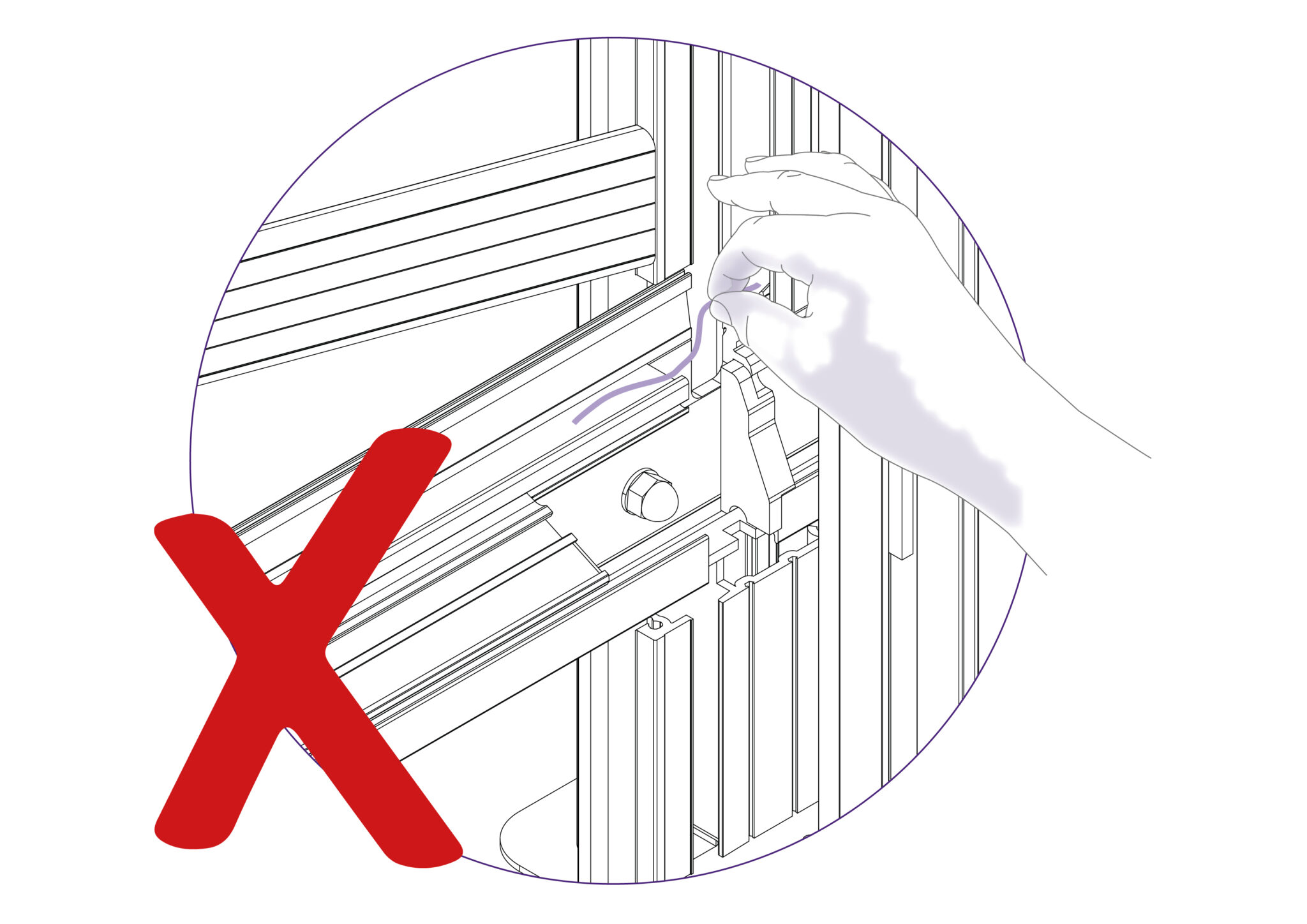
Do not wipe the Squaring Arm channels or remove any debris with fingers, as it may contain sharp particles such as glass.
Use a vacuum cleaner if possible. If a soft brush is used, work slowly and do not allow particles to flick off the bristles.
NOTE: It is important to use the correct lubrication (defined below for the respective areas) as ordinary oils and solvents can adversely affect the materials.
NOTE: Do not use penetrating oils (i.e. WD-40) for lubrication on this machine.
Guide rods and rollers:
Wipe using cleaning solvent on a cloth, and lubricate the surfaces very lightly with petroleum jelly. The axles of the rollers are lubricated and sealed for life and need no further attention.
Lubrication frequency: After 2 weeks of use and then every month thereafter (except on axles of rollers).
Ratchet system:
Use a light oil (3 in 1), one or two drops on the pivot point and one drop on the ratchet teeth.
Lubrication frequency: After 2 weeks of use and then every month thereafter.
Balance weight:
Silicon Lubricant sprayed in from the top of the balance weight opening whilst the Twin Wheel Cutting Head is parked at the top of the machine.
Lubrication frequency: After 2 weeks of use and then every month thereafter.
Ratchet release bar:
Smear edge with petroleum jelly.
Lubrication frequency: After 2 weeks of use and then every month thereafter.
Swinging Arm:
Petroleum jelly around curved slot.
Lubrication frequency: After 2 weeks of use and then every month thereafter.
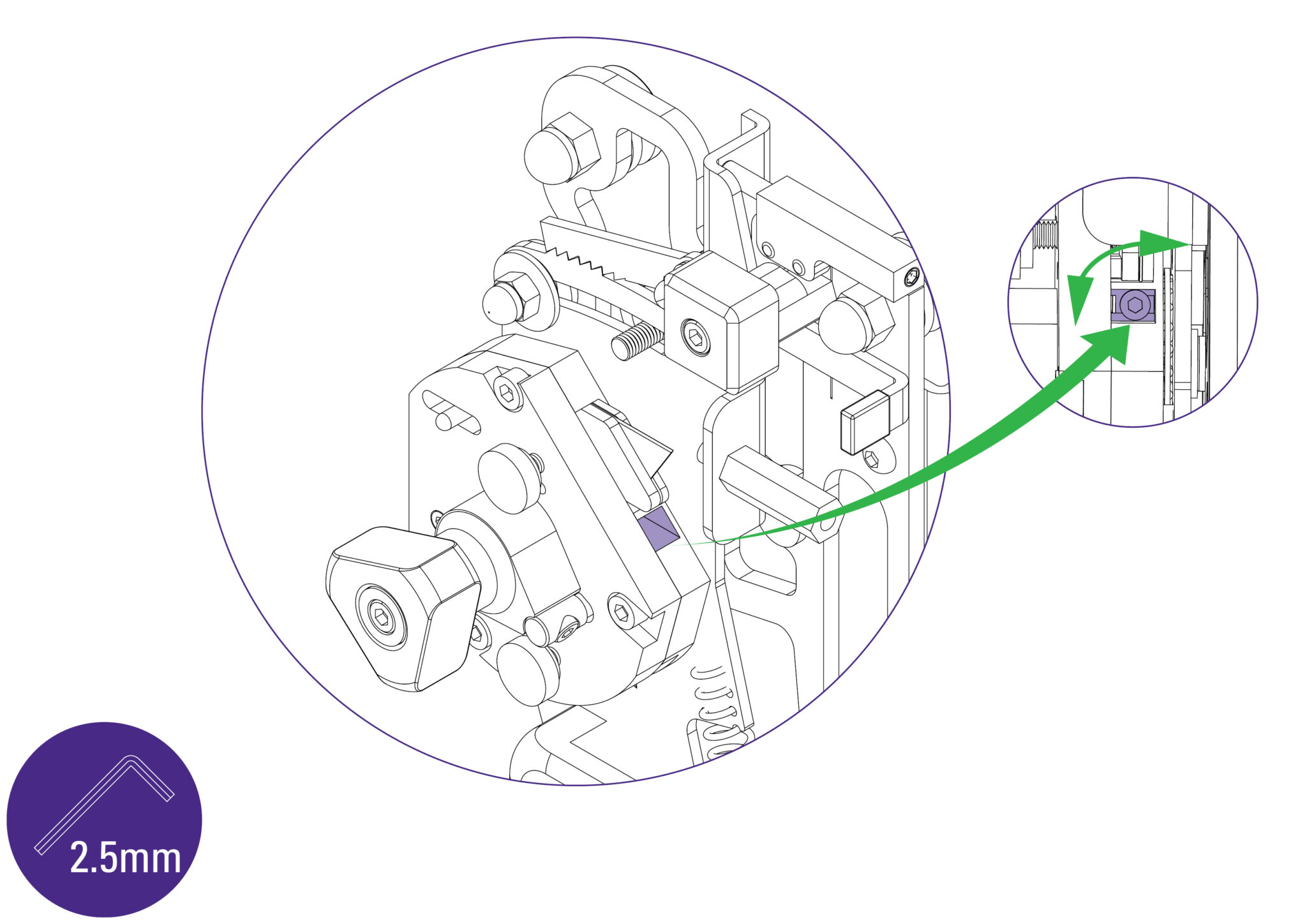
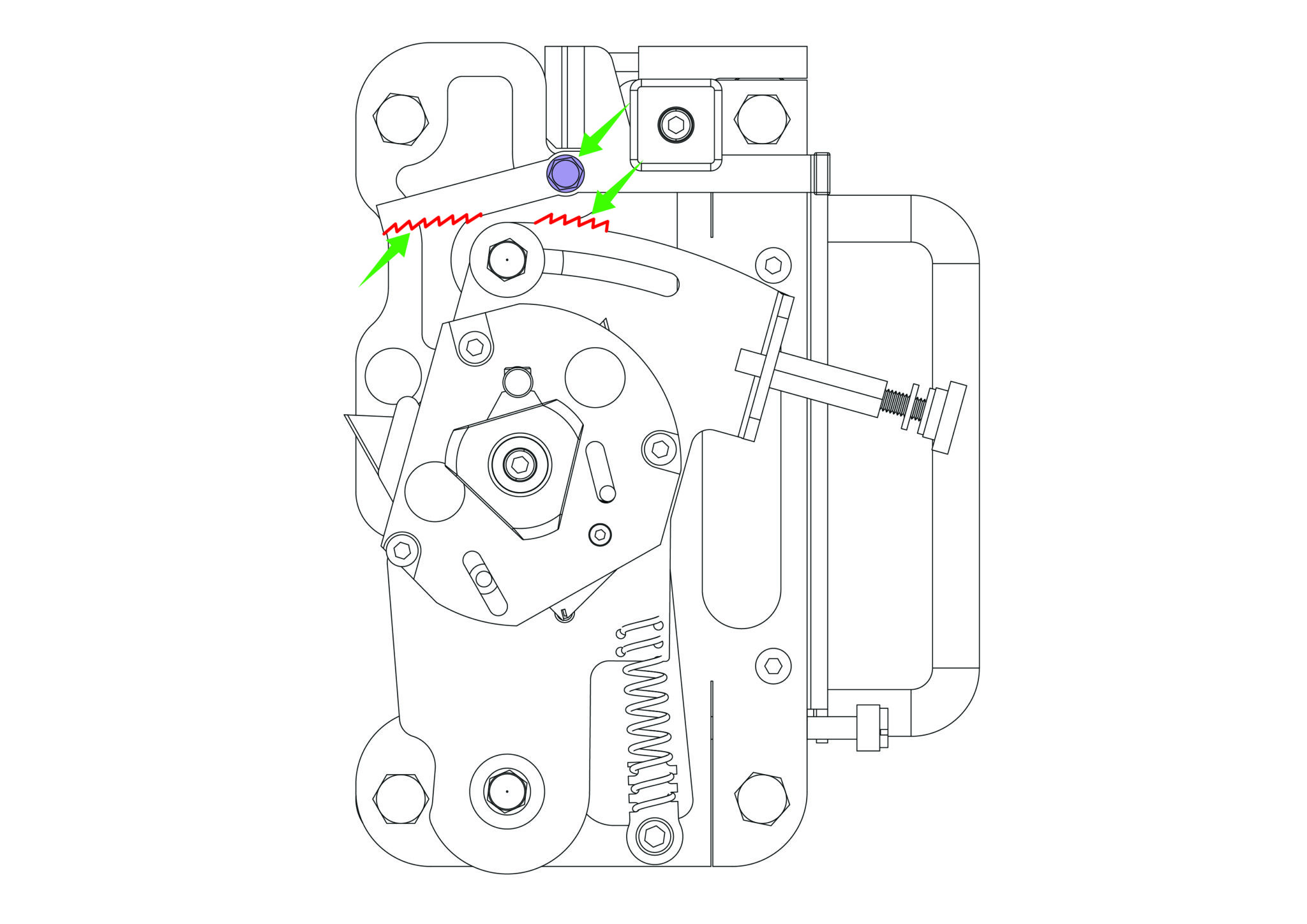
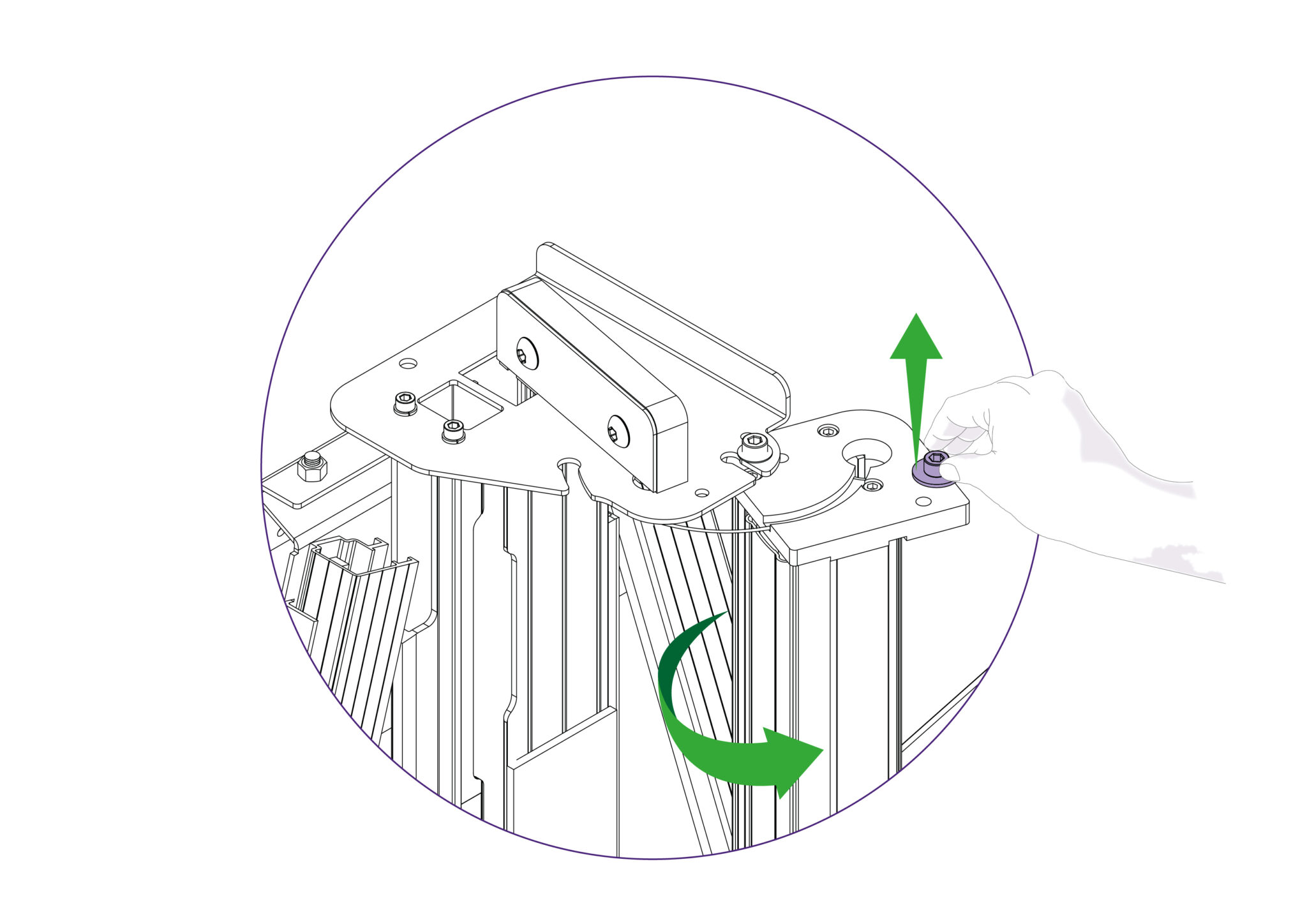
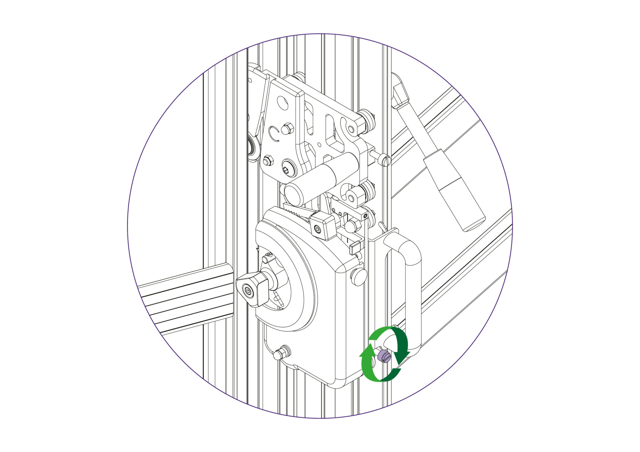
The pressure of the clamp is in relation to the amount of pressure applied to the operating handle, however in time the maximum clamping pressure can reduce due to wear on the friction block (hidden within the machine).
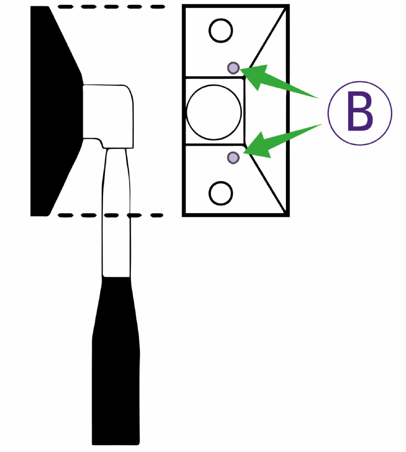
Compensation for this can be made by adjusting the two small grub screws (labelled B) in the operating handle housing as shown. Turning the screws lightly clockwise until they stop moving and then undoing them by quarter of a turn should provide an acceptable pressure, but further small adjustments can be made to increase or decrease the pressure as required.
NOTE: Care should be taken not to tighten either grub screw fully or this will result in undue wear of the friction plate
When cutting tough materials it is essential that the clamping system operates at its’ optimum, the moving clamp bar must press evenly onto the board being cut and not clamp it only at the top or bottom.
To check for parallel clamping, use 2 pieces of A4 paper, place one under the bottom end of the clamp and hold the other at the top end whilst depressing the clamp handle. Then check that the clamp firmly grips the pieces of paper. If it does not clamp both pieces firmly, follow the steps below.
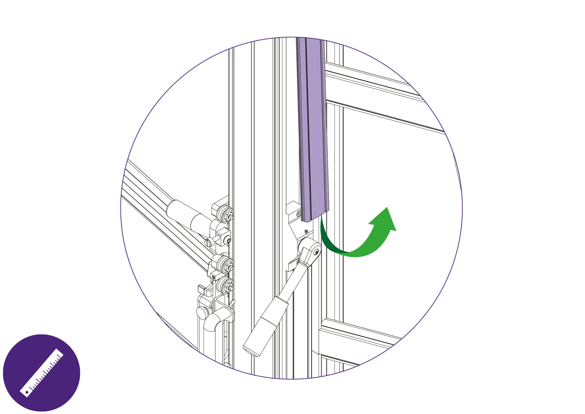
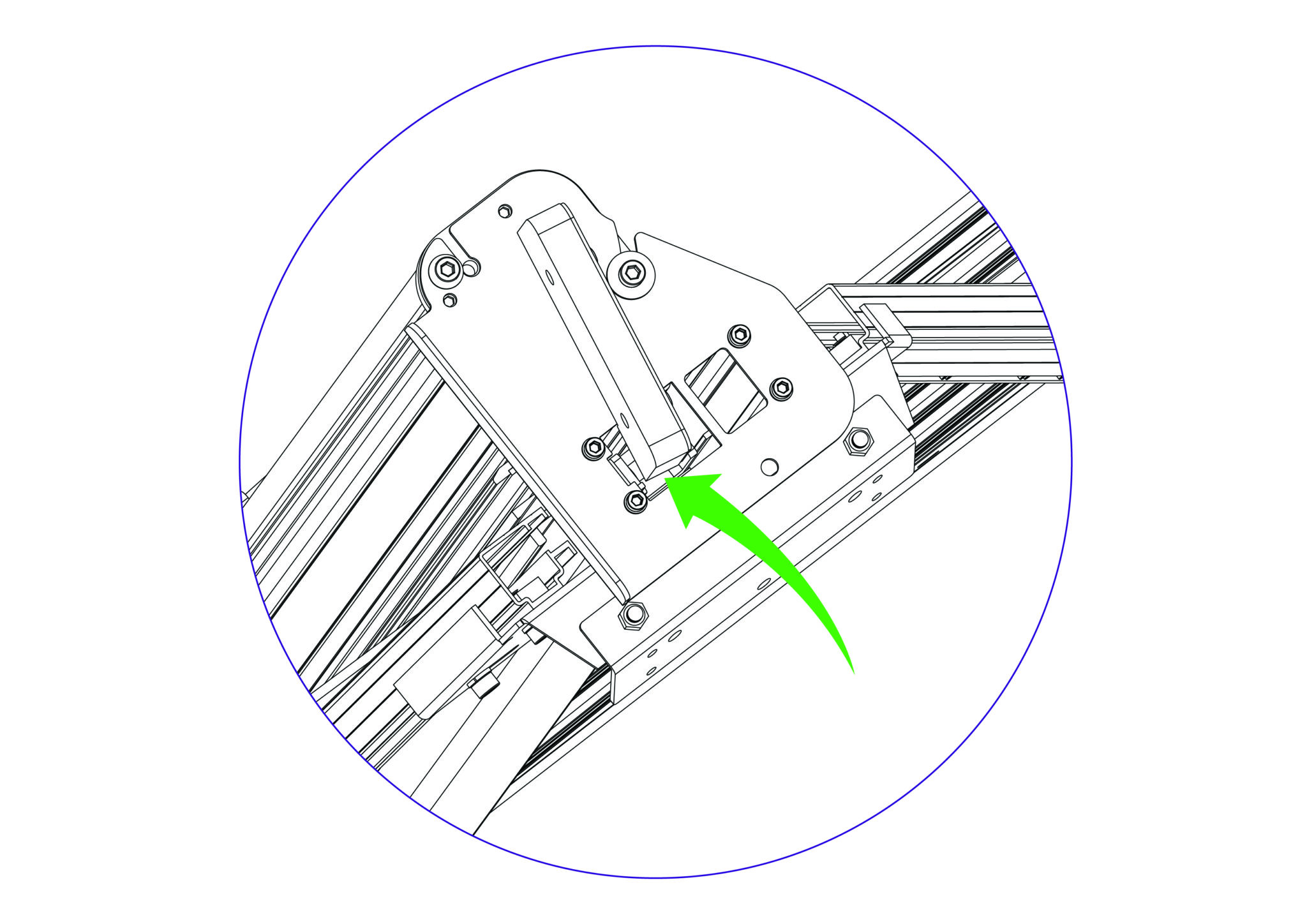
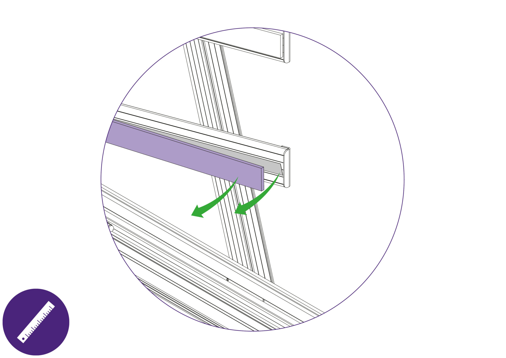
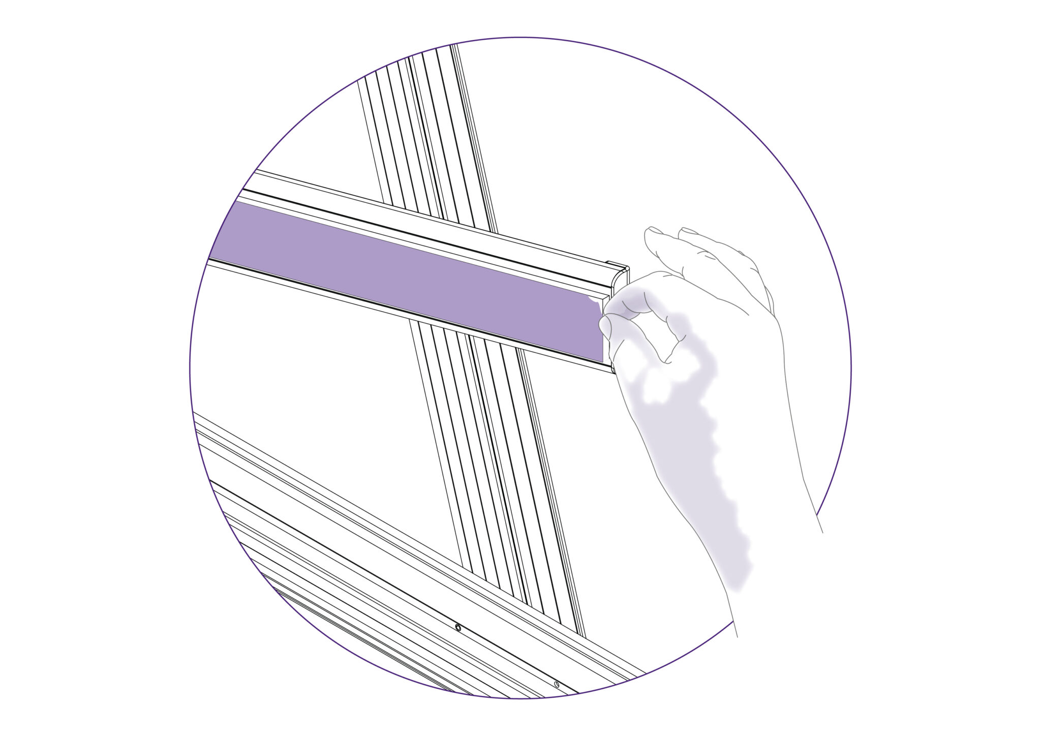
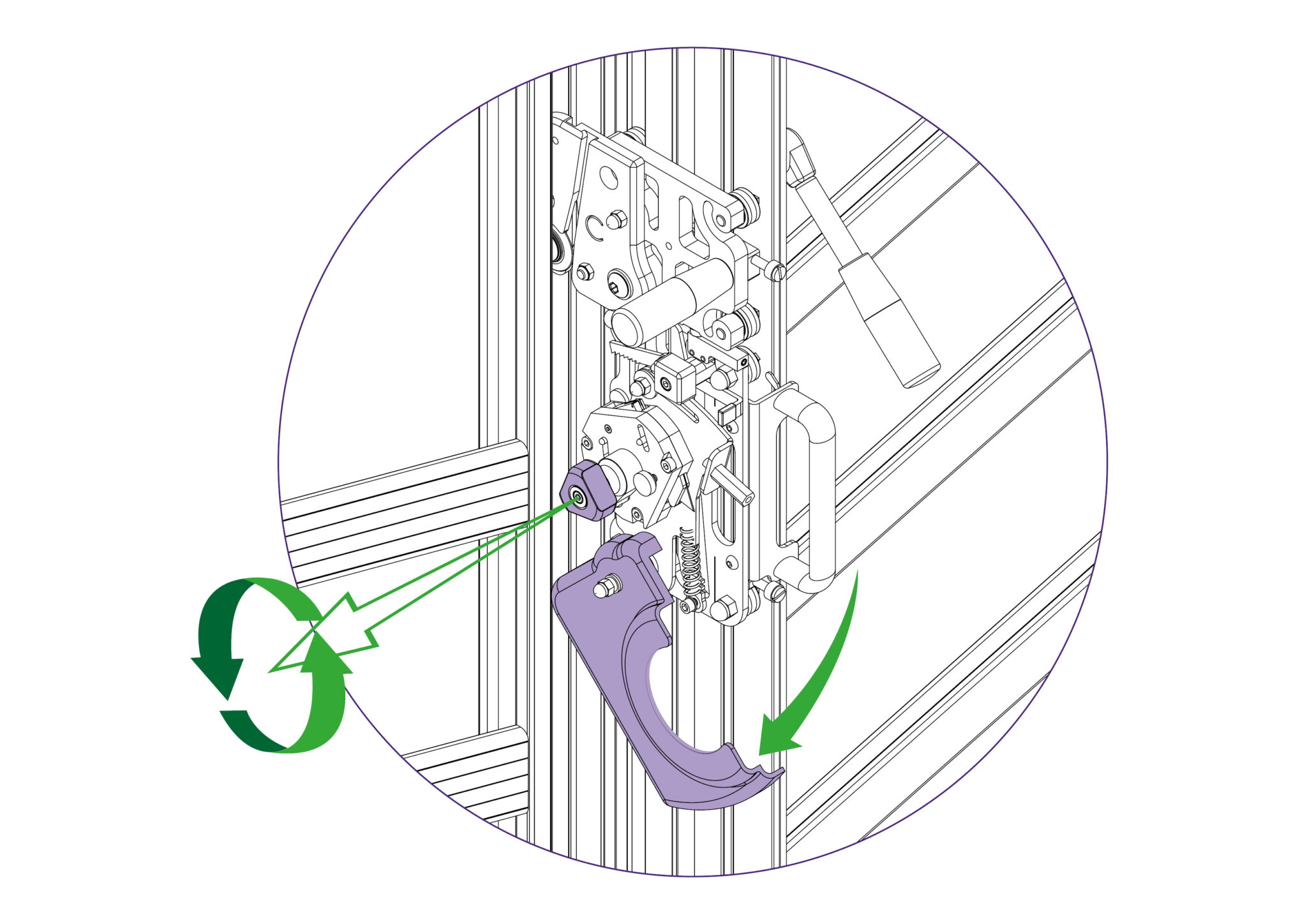
Open the clamp by at least 1-2mm and remove the plastic cover strip situated above the clamp handle it just clips out of place, use the end of a small steel rule to lever it from its’ groove.
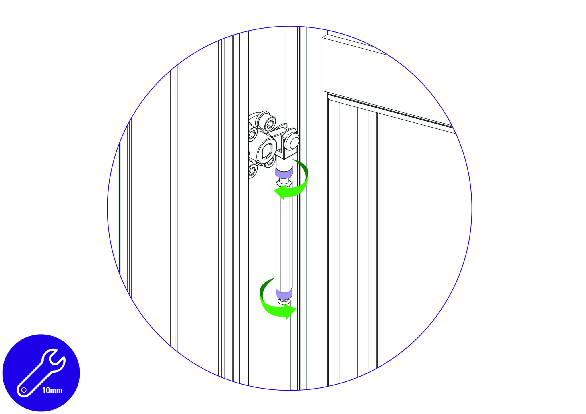
The clamp adjuster is at the top end of the push rod and is locked in position by two locking nuts.
The top nut has a normal right-handed thread, slacken it using a 10mm wrench by turning it counter clockwise when looking from below.
Now slacken the bottom nut, which has a left hand thread and should be turned clockwise when viewed from below.
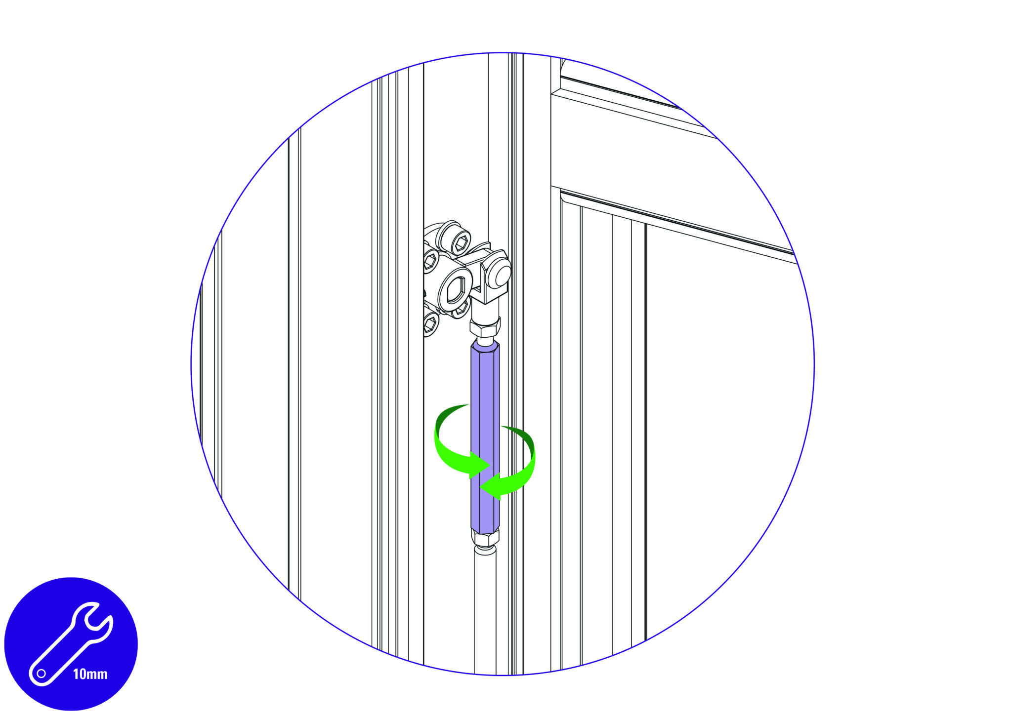
The ‘adjuster’ is the hexagonal bar between the two nuts, and by turning it with the spanner it alters the clamps alignment with the back of the machine.
Rotate the adjuster whilst observing the clamp from the side and bring the clamp into parallel.
Repeat the initial check using the 2 pieces of A4 paper, to ensure the clamp has been brought into parallel.
Once parallel is confirmed, tighten the two locking nuts whilst holding the adjuster in position with the second spanner. Then operate the clamp a few times and check/adjust further if necessary.
Finally, replace the plastic cover strip.
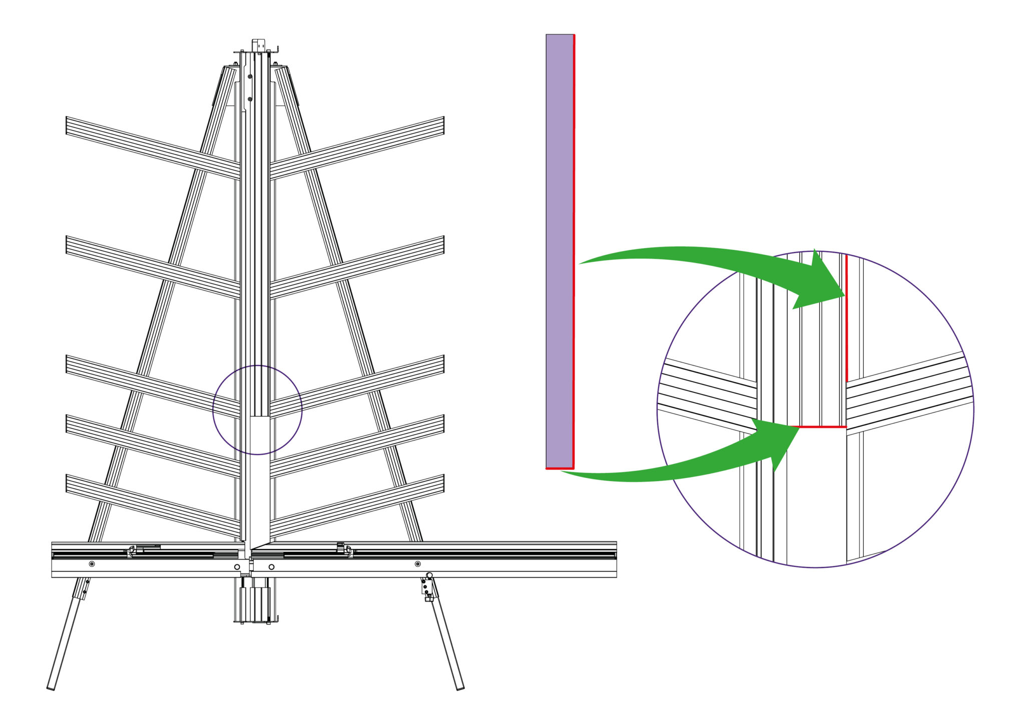
Replacement Blue Support Boards are available from Keencut or your distributor.
The Blue Support Boards on the Main Body and Support Arms offer an element of protection to materials being cut, in particular coated glass surfaces. Over the machine’s lifetime it could be expected that these Blue Support Boards could experience wear and may need replacing.
Removing from the support arm:
Slightly remove the edge of the Blue Support Board using a thin and rigid item such as a ruler. Peel the layers of double sided tape from the support arm if any tape remains on the surfaces. Clean the surface of the support arm with white spirit to clear any remnants of adhesive.
Ensure the surface is clean and dry before fitting the new Blue Support Boards onto the Support Arms.

Placing onto the support arms:
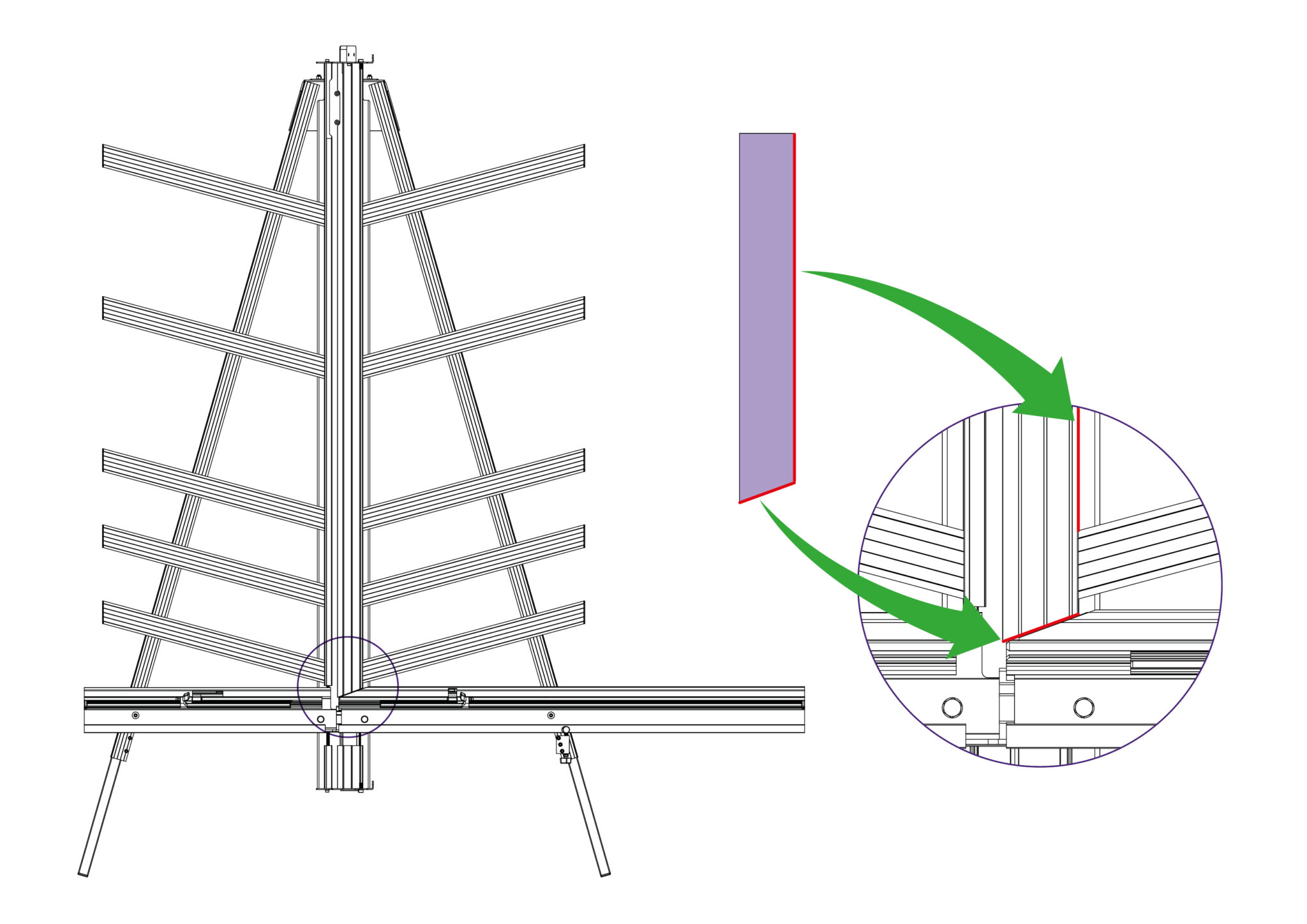
Peel the release paper from the adhesive face and align the angled face of the board with the angled face of the Support Arm that does not have the end cap attached. Ensure that the board in central to the Support Arm and that it does not overlap on to the Main Body face.
Proceed to lower the Blue Support Board onto the Support Arm surface, starting from the aligned edge.
Remove the protective film.
NOTE: Blue Support Boards on the support arms should naturally be raised compared to those on the main body.
Removing from the main body:
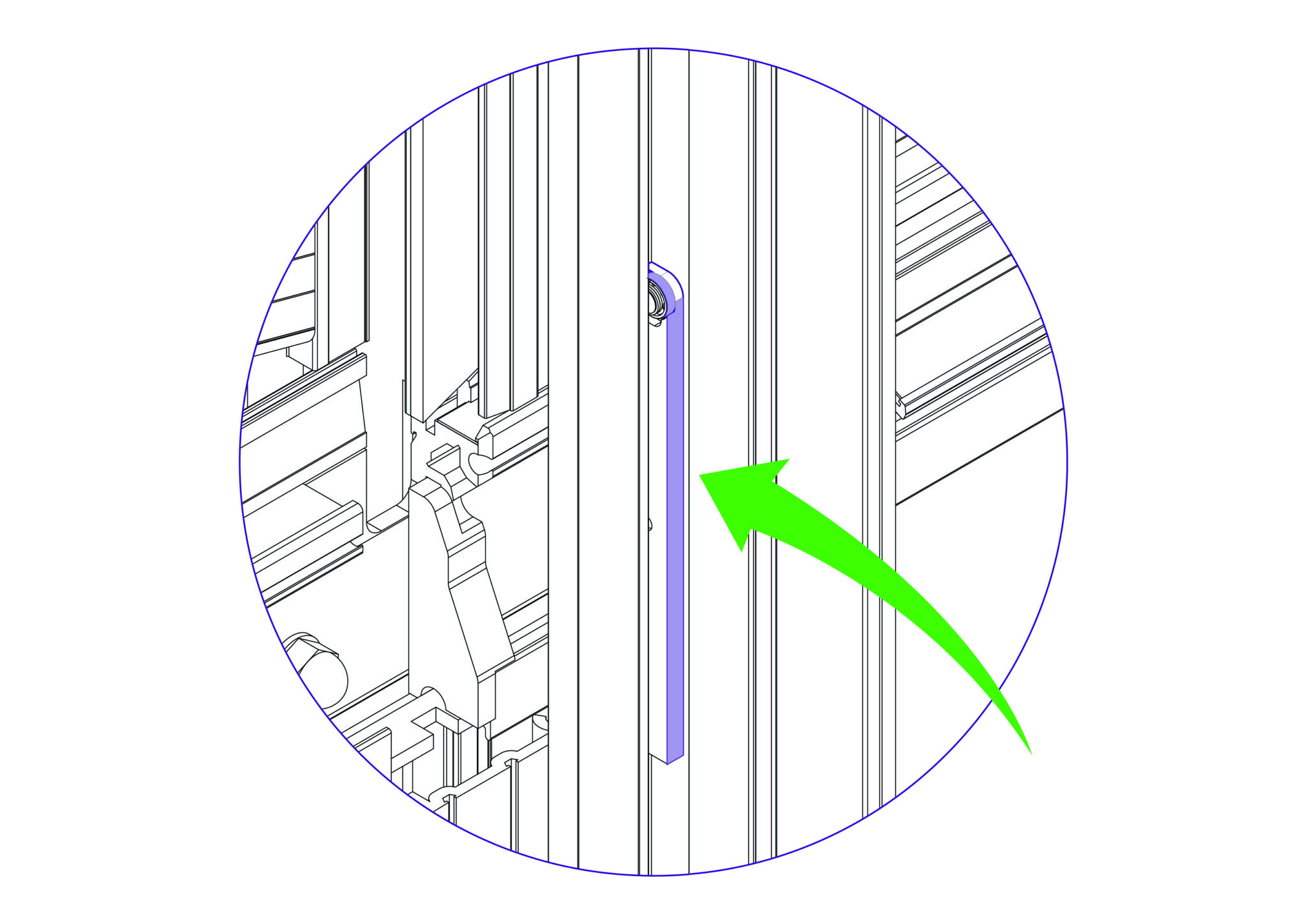
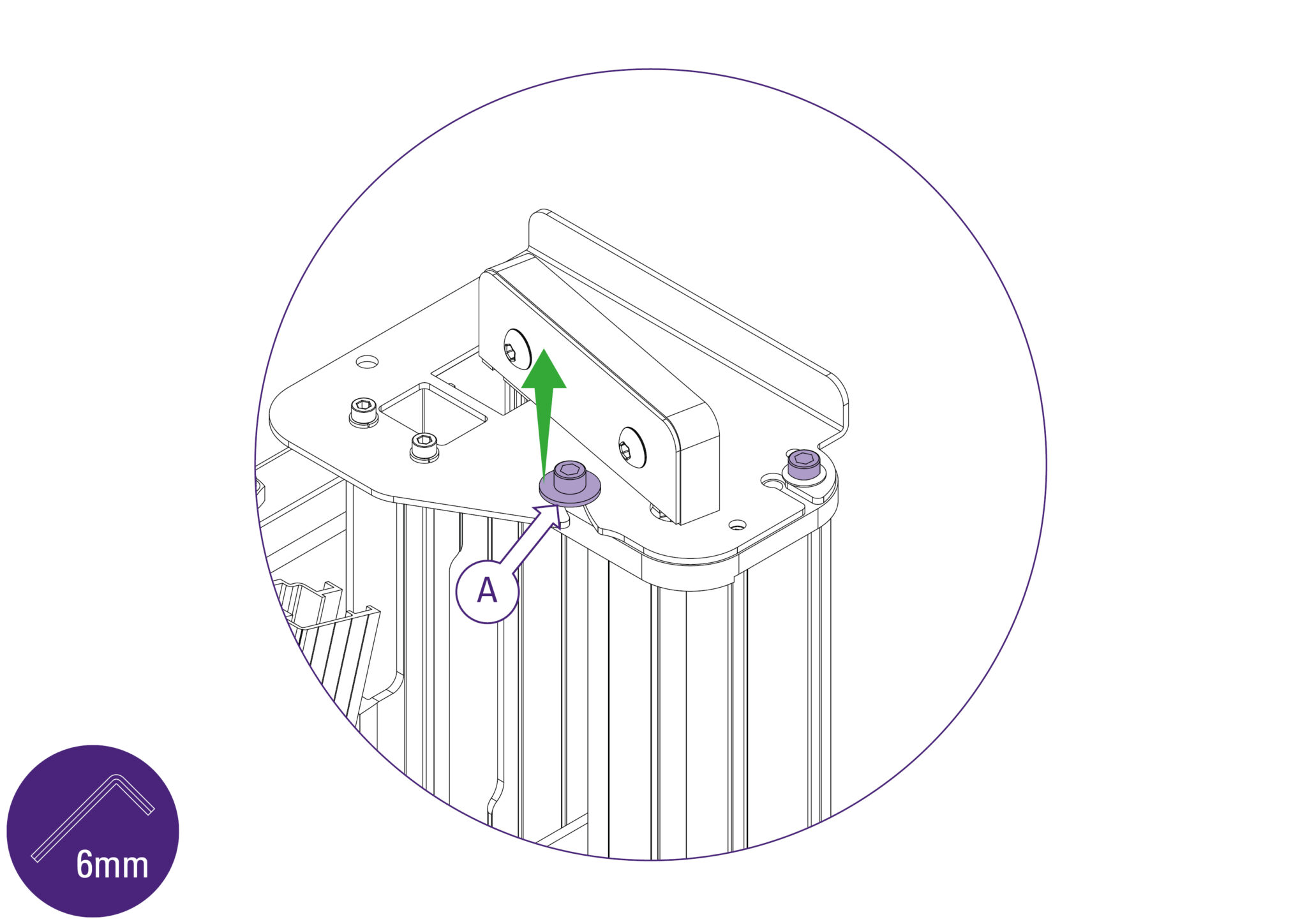
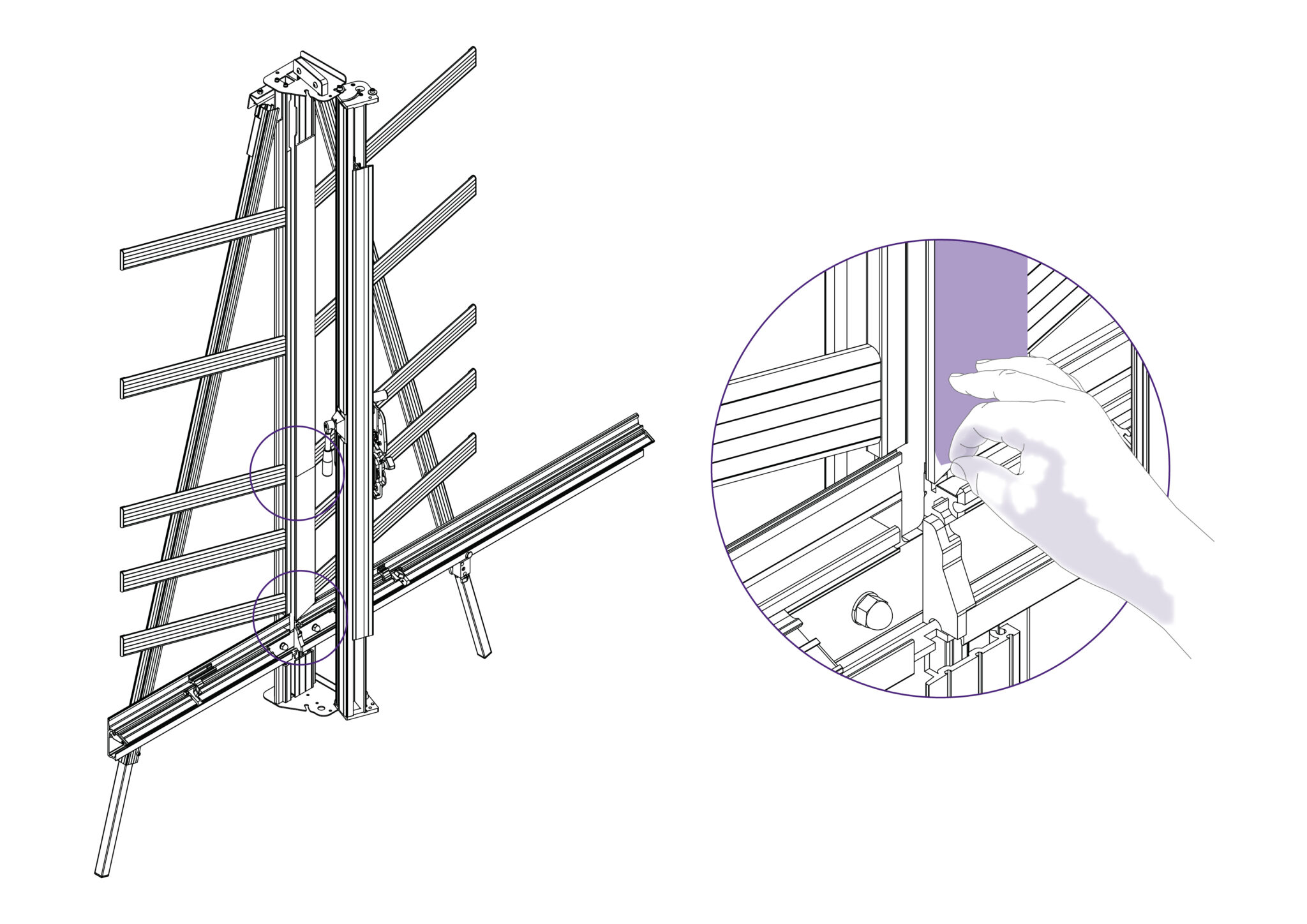
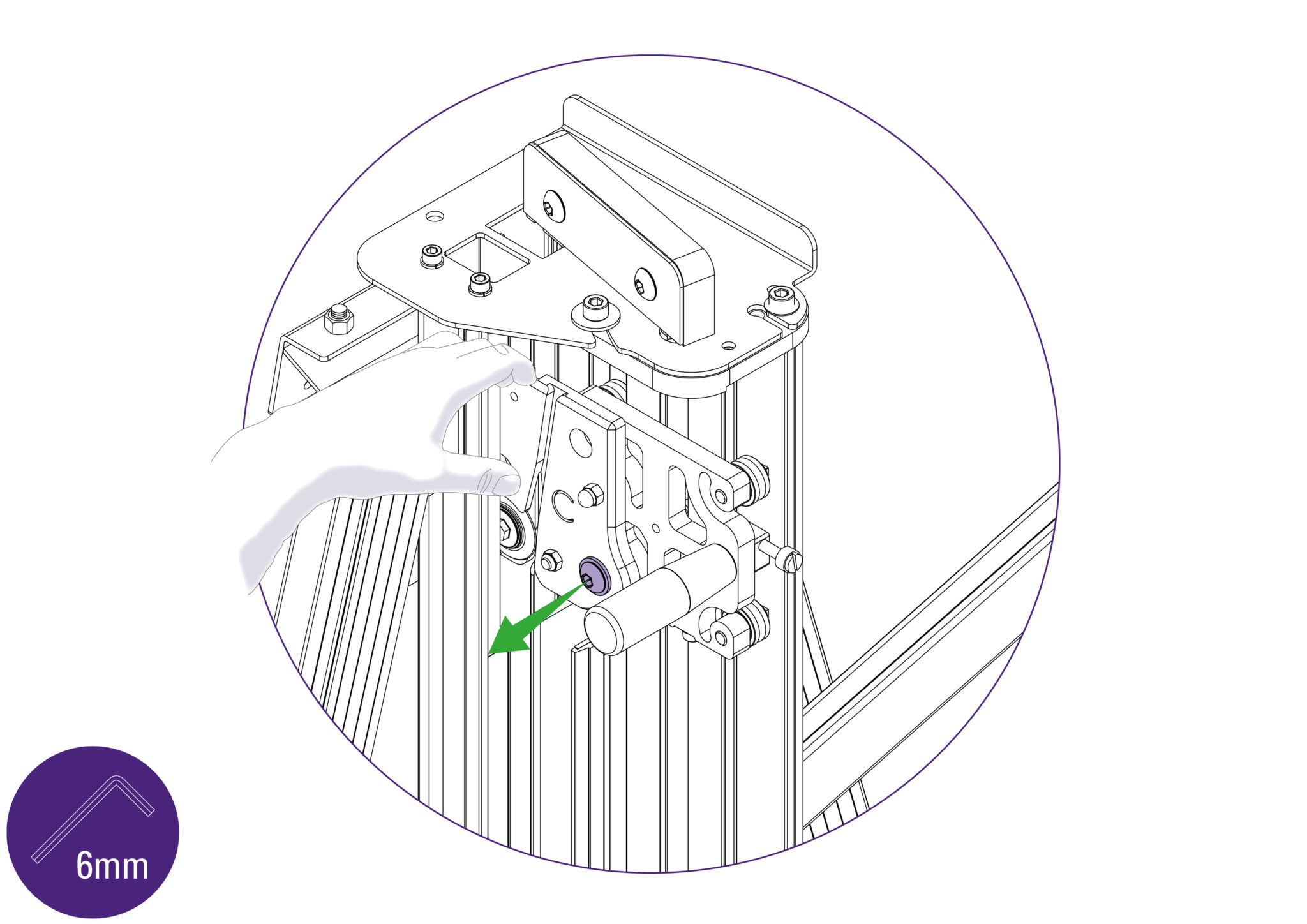
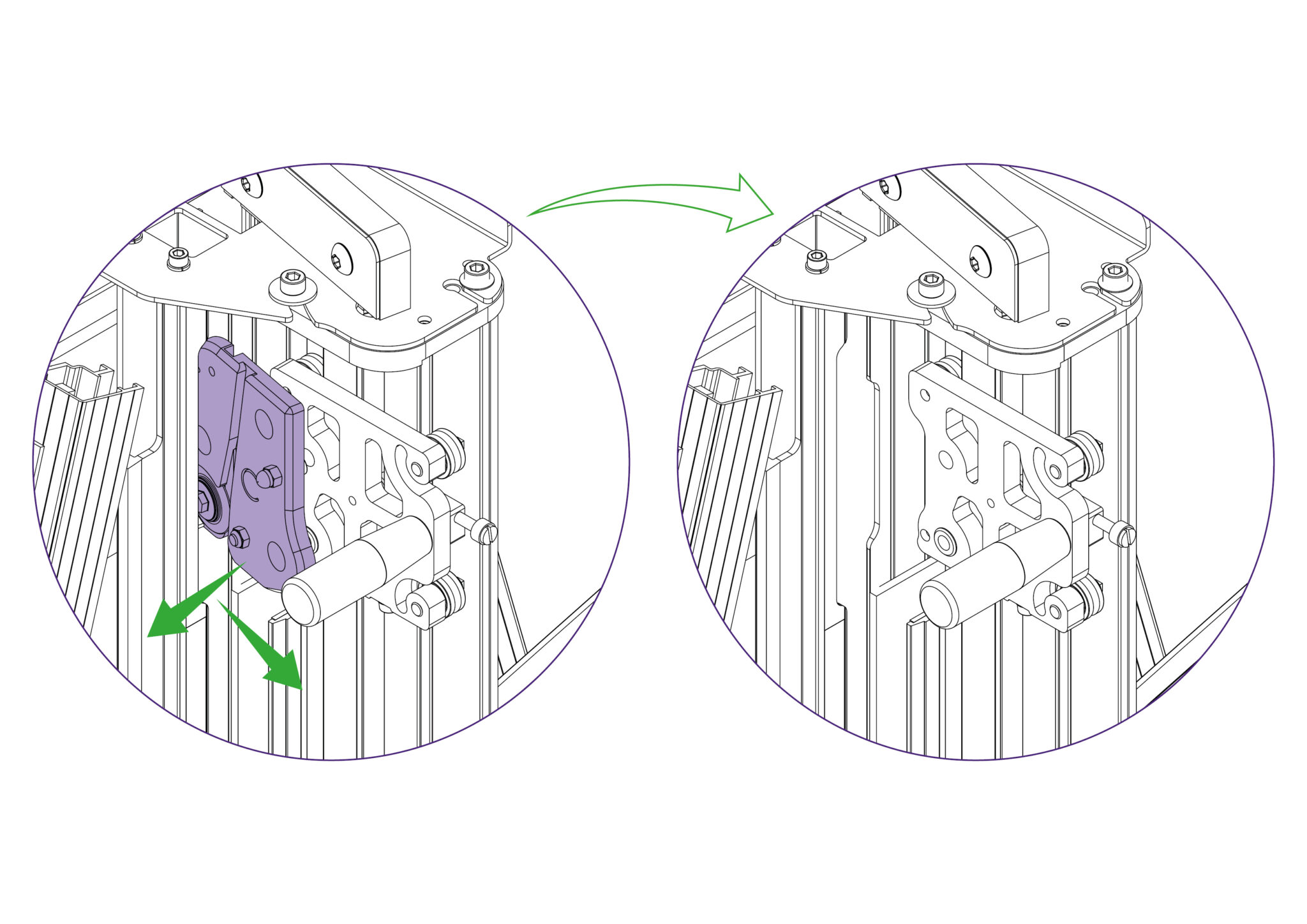
Loosen the two screws using the 6mm Allen key (hex key) on the mount plate of the machine, as indicated. The left hand one needs to be undone enough for the flanged washer (A) to be lifted clear of the top plate, or it can be entirely removed if you prefer but do not remove the other screw. Repeat this at the bottom end of the machine.
Ensure the clamp is fully open. Then whilst lifting the flanged washer clear with one hand, take hold of the Slideway and twist it out as shown. Once the flanged washer is clear of the top plate it can be released. It is normal to feel the balance weight cord working against you.
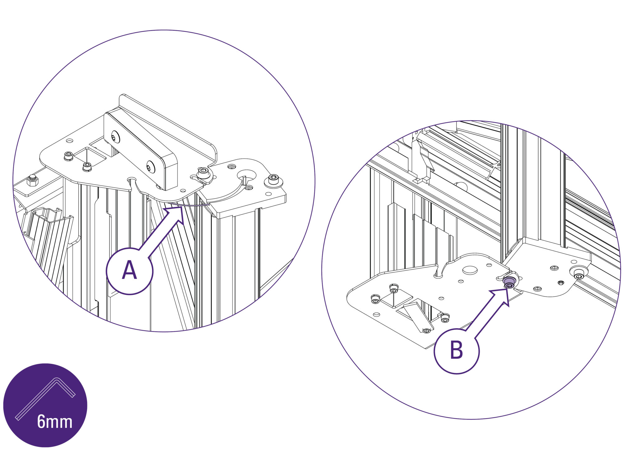
You will feel the balance weight cord (A) working against you and try to twist the slideway back, open the slideway carefully and watch that the balance weight cord (A) does not become trapped. Tighten the bottom Allen screw (B), as shown, to hold the slideway open in the maintenance position.
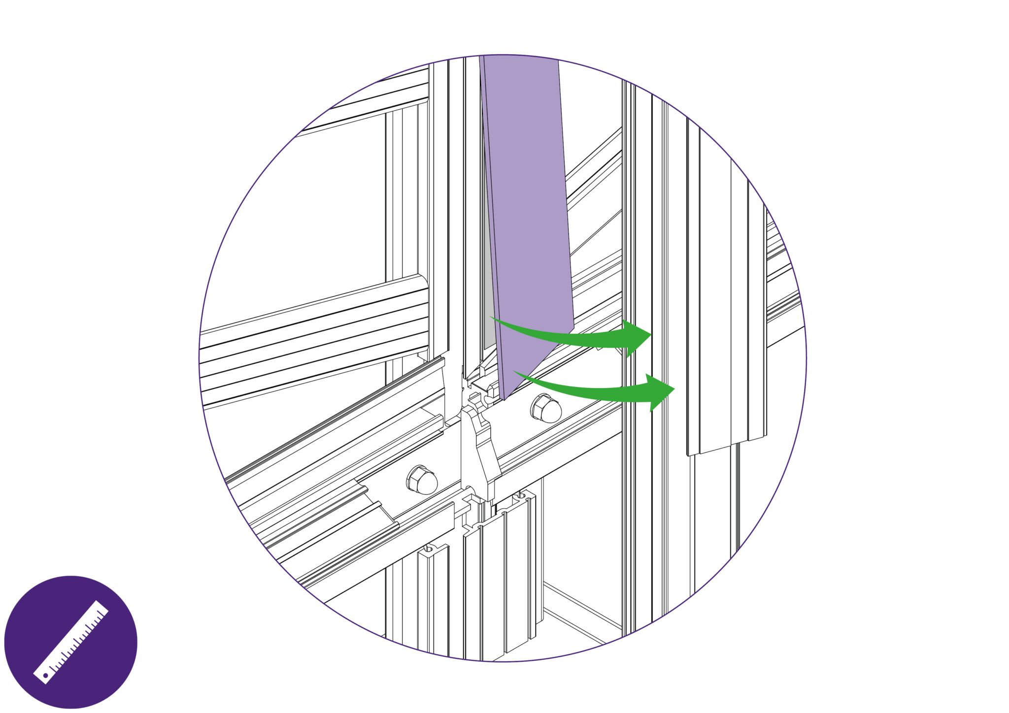
With the Blue Support Board now accessible, slightly remove the edge away using a thin and rigid item such as a ruler. Peel the layers of double sided tape from the Main Body if any tape remains on the surfaces. Clean the surface of the Main Body with white spirit to clear any remnants of adhesive.
Follow through with the same steps for the other Blue Support Board on the Main Body.
Ensure any remnant of cleaning spirit is dried off before proceeding to place the new Blue Support Boards onto the Main Body.
Placing onto the main body:
Peel the release paper off the double sided tape and align the angled face of the lower board with the angled face of the Main Body. Ensure that the straight face identified is aligned with the face of the Main Body and that it does not overlap on to the Support Arms.
Proceed to lower the lower Blue Support Board onto the Main Body, starting from the aligned edges.
Peel the release paper off the double sided tape and align the bottom face of the top board. Ensure that the flat face identified is also aligned with the face of the Main Body.
Proceed to lower the top Blue Support Board onto the Main Body, starting from the aligned edges.
Remove the protective film.
Proceed to return the slideway back into operating position and ensure that the cutting head runs up and down the full length of the slideway. Fasten the respective screws tightly.
Replacement medium utility blades are available from Keencut or your distributor.
Move the multi-tool cutter to a comfortable height and lock it in position using the white nylon locking screw. Ensure that this is done tightly.
Unlock and swing down the cutter guard. Then rotate the turret so the cutting blade is facing towards you.
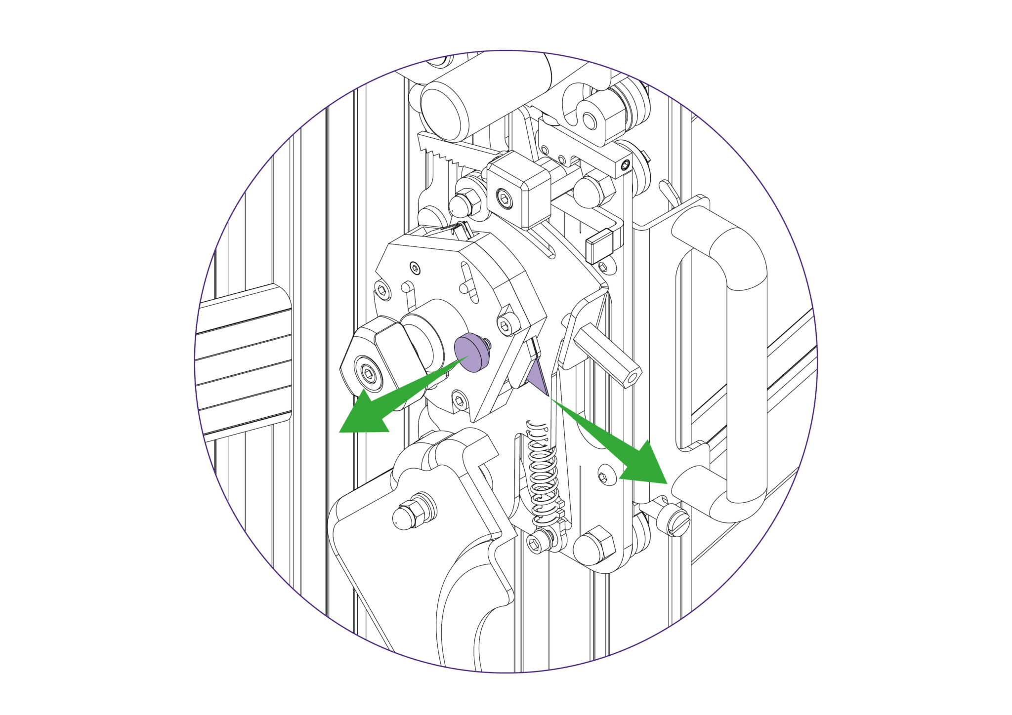
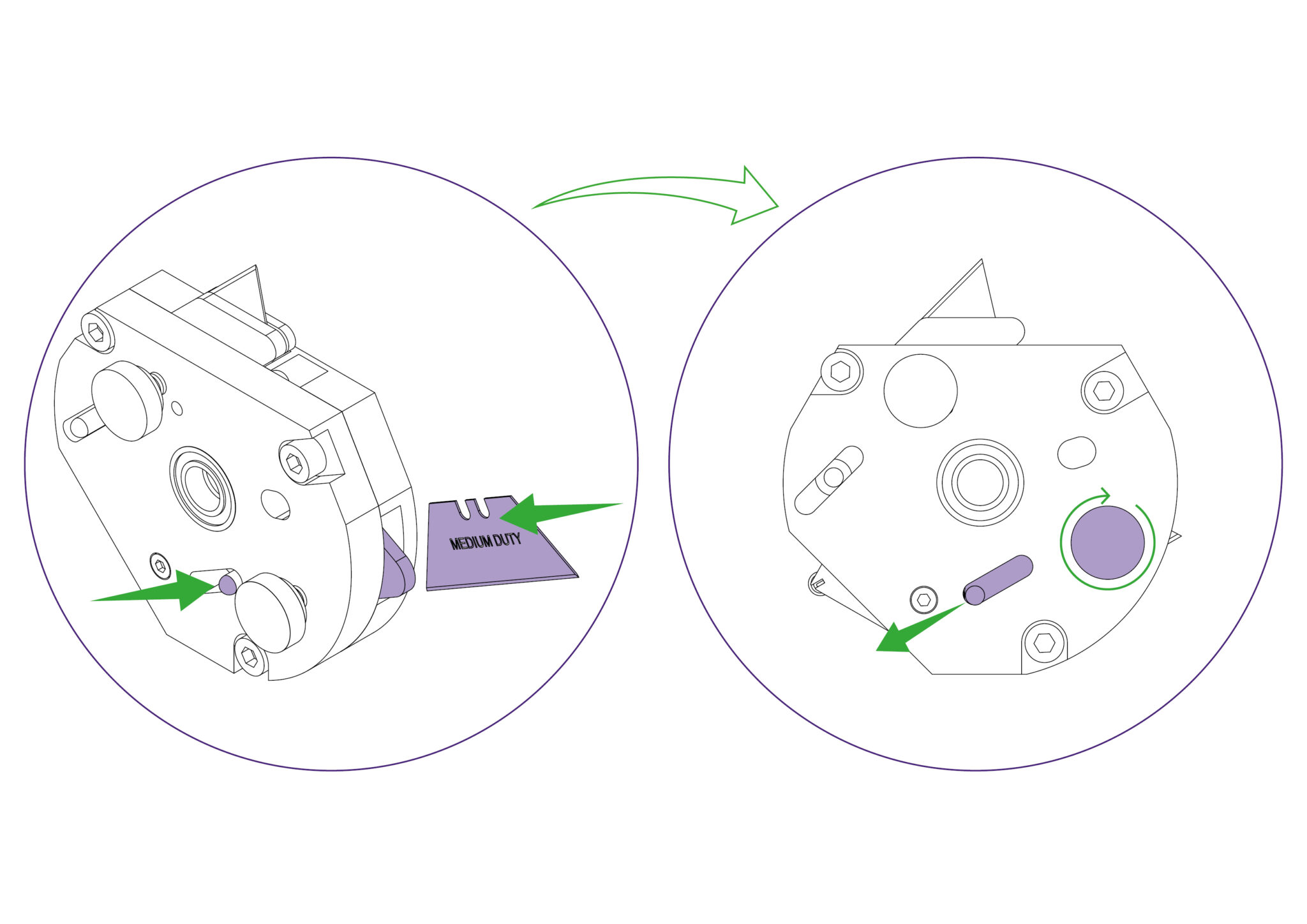
To change the cutting blade, loosen the blade clamping screw to release the blade.
Change or turn over the blade, insert it back into the turret as far as it will go. At this point the position of the blade support plates can be adjusted to suit the thickness of material being cut, and further tightening of the screw will clamp the blade in position.
Rotate the turret back to the cutting position and check the blade support plates with respect to the thickness of the material being cut.
Replace the guard, ensuring it is locked closed.
Replacement medium utility blades are available from Keencut or your distributor.

Move the multi-tool cutter to a comfortable height and lock it in position using the white nylon locking screw. Ensure that this is done tightly.
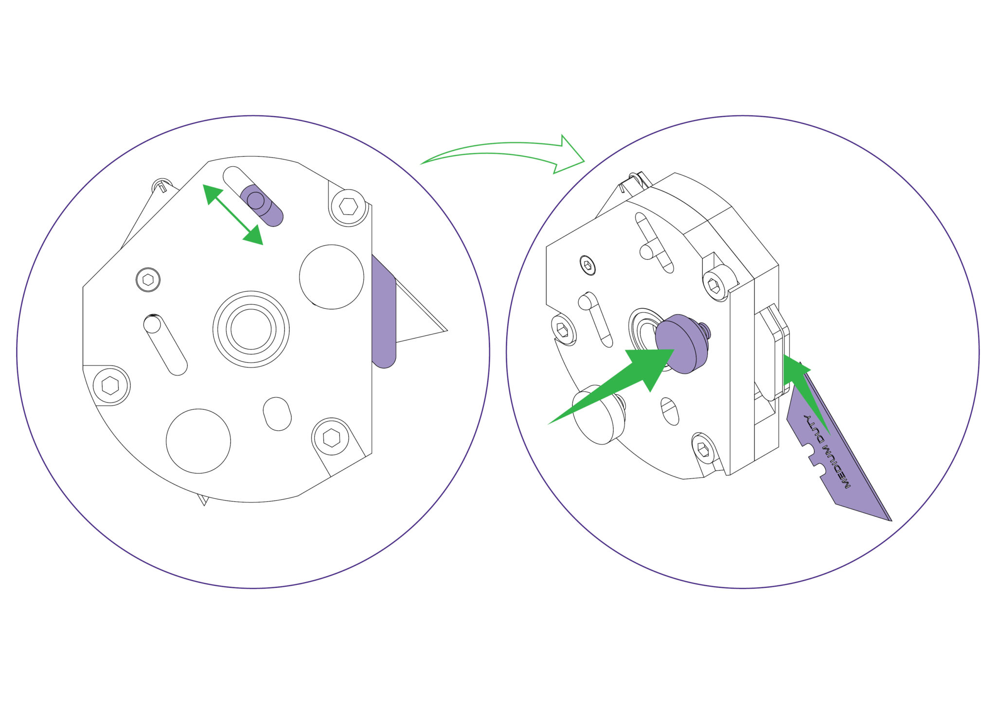
Unlock and swing down the cutter guard. Then rotate the turret so the scoring blade is facing towards you.
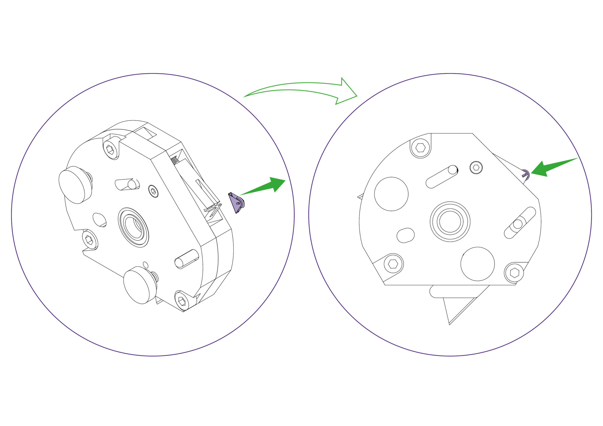
Release the blade clamping screw. Eject the medium duty utility blade using the black ejector pin.
Replace the blade to the right of the clamping plate, push the blade in as far as it will go, and tighten the blade clamping screw.
Rotate the turret back to the scoring position. Replace the guard ensuring it is locked closed.
Replacement wheels are available from Keencut or your distributor.
Move the multi-tool cutter to a comfortable height and lock it in position using the white nylon locking screw. Ensure that this is done tightly.
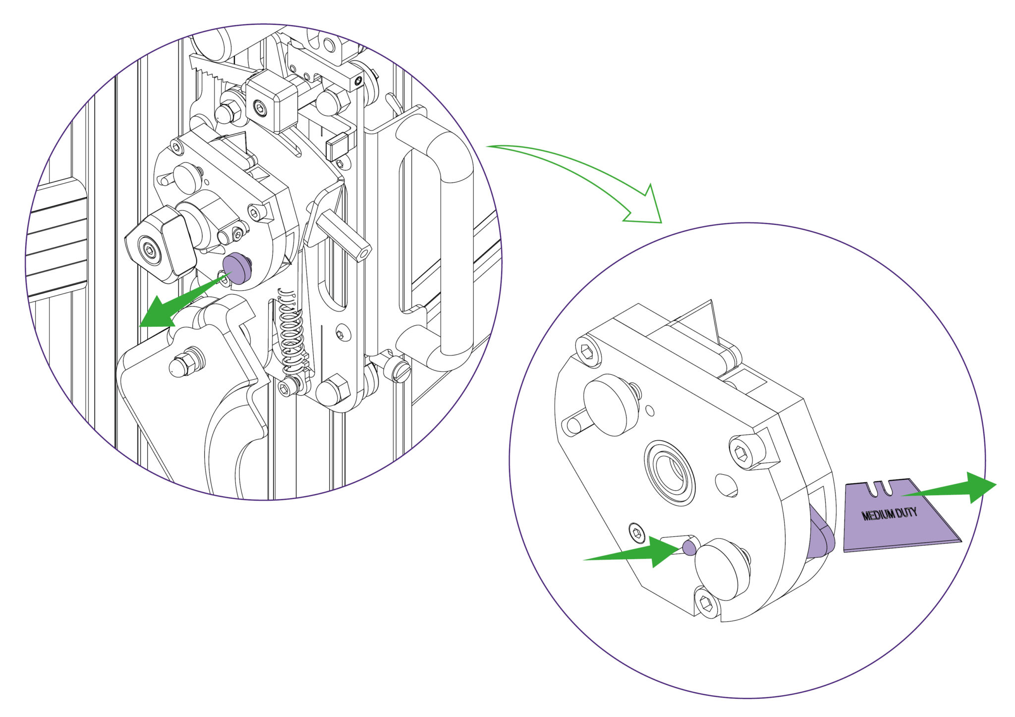
Unlock and swing down the cutter guard. Then rotate the turret so the glass wheel is facing towards you.
A small screwdriver or piece of stiff wire (opened paperclip) can be used to push the edge of the triangular clip and rotate it out of the groove. Pull the clip to remove the wheel with it. Then replace it with the new wheel and clip assembly.
Rotate the turret back to the glass cutting position. Replace the guard ensuring it is locked closed.
Replacement twin wheel cutters are available from Keencut or your distributor.
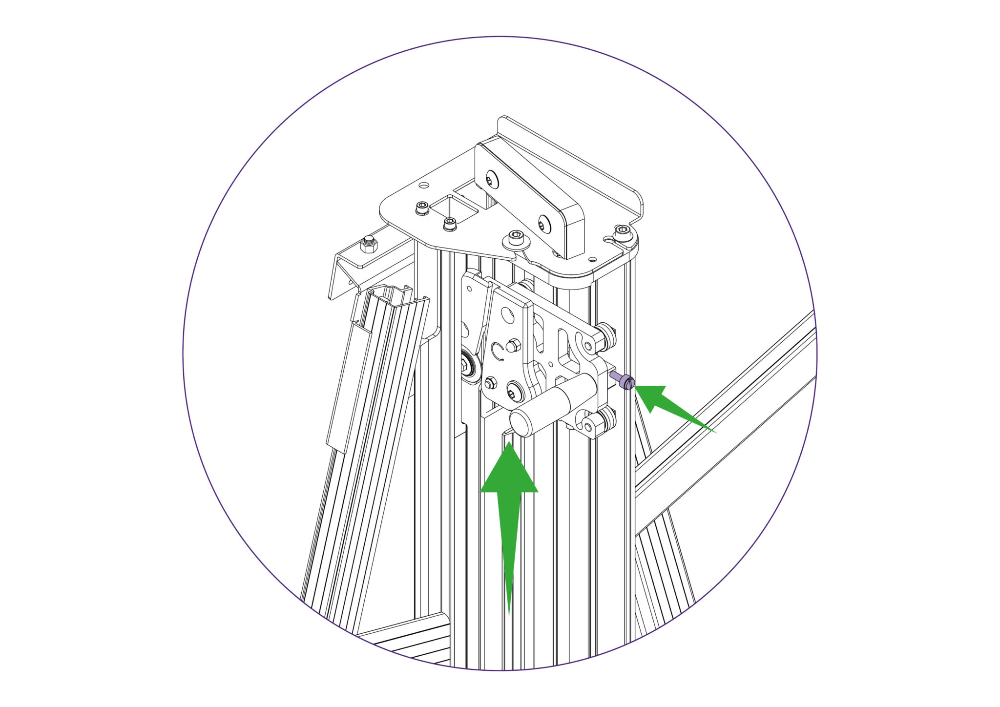
Move the twin wheel cutter to the top of the machine (adjacent to the open channel) and lock it in position using the white nylon locking screw. Ensure that this is done tightly.
Hold the twin wheel cutter on to the Cutting Head whilst removing the screw with a 6mm Allen Key.
Slide the twin wheel cutter out through the open channel in the main body and lift it out. Reverse the procedure to fit the replacement twin wheel cutter, ensuring it is properly located flat against the Cutting Head before fastening the screw with the 6mm Allen Key.
This User Guide for the Excalibur 6000 gives advice on cutting techniques, care and maintenance of your machine.
Before using your machine make sure that you have installed and calibrated it correctly. Full details are in the Installation Manual.
Ⓒ Keencut 2020 | Baird Rd, Corby NN17 5ZA United Kingdom | Contact us
Created by DeType | Privacy | Website Disclaimer | Terms & Conditions