
Excalibur 6000 installation manual – Installation
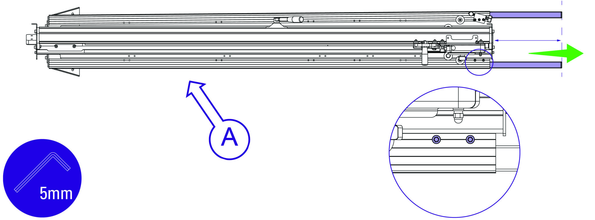
Slacken the bottom two screws on each leg using the 5mm Allen (hex) key and extend the
telescopic parts equally to the desired length.
Re-tighten screws firmly to clamp legs in position.
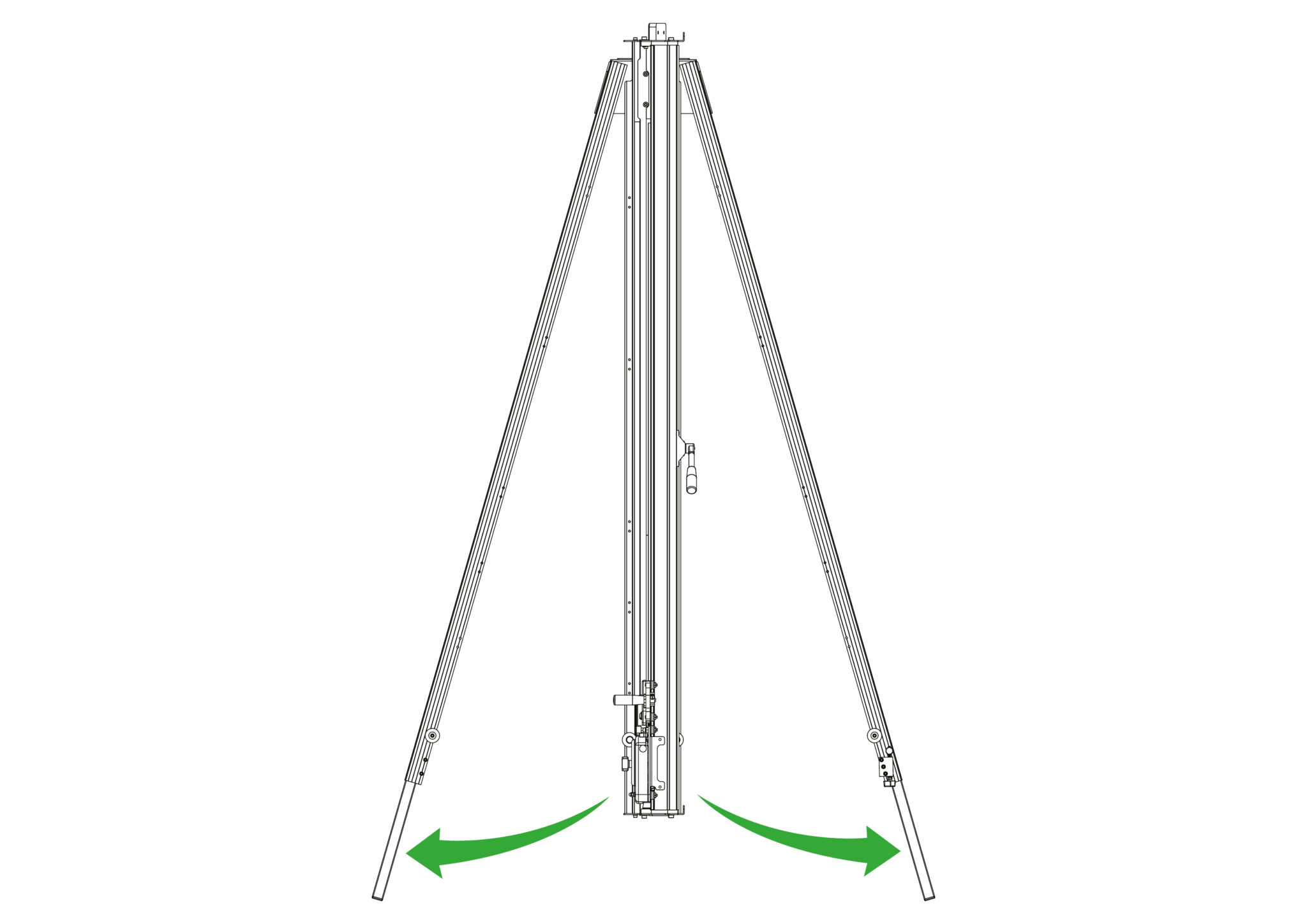
Swing both legs outwards as far as they will go.
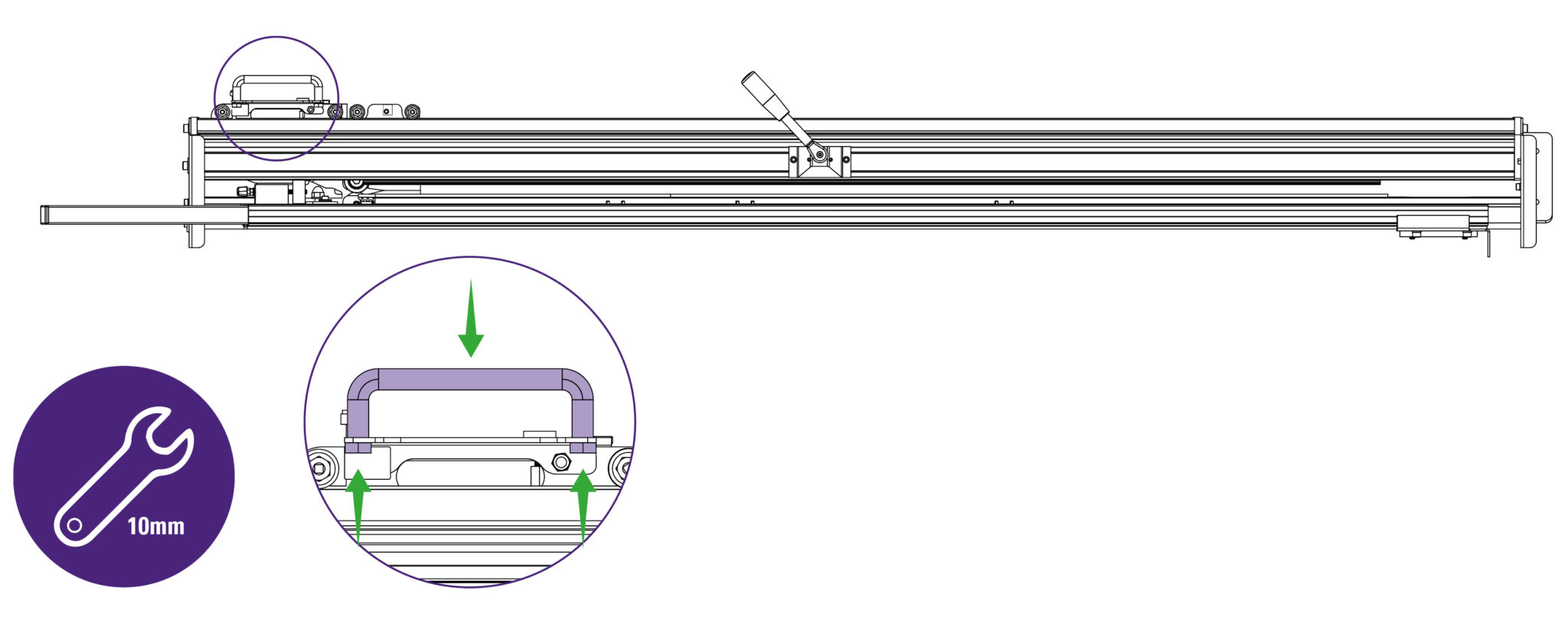
Align the handle (part P) with the cutting head’s holes and fasten the wing bolts (part Q) from the other side securely.
| Do this firmly |
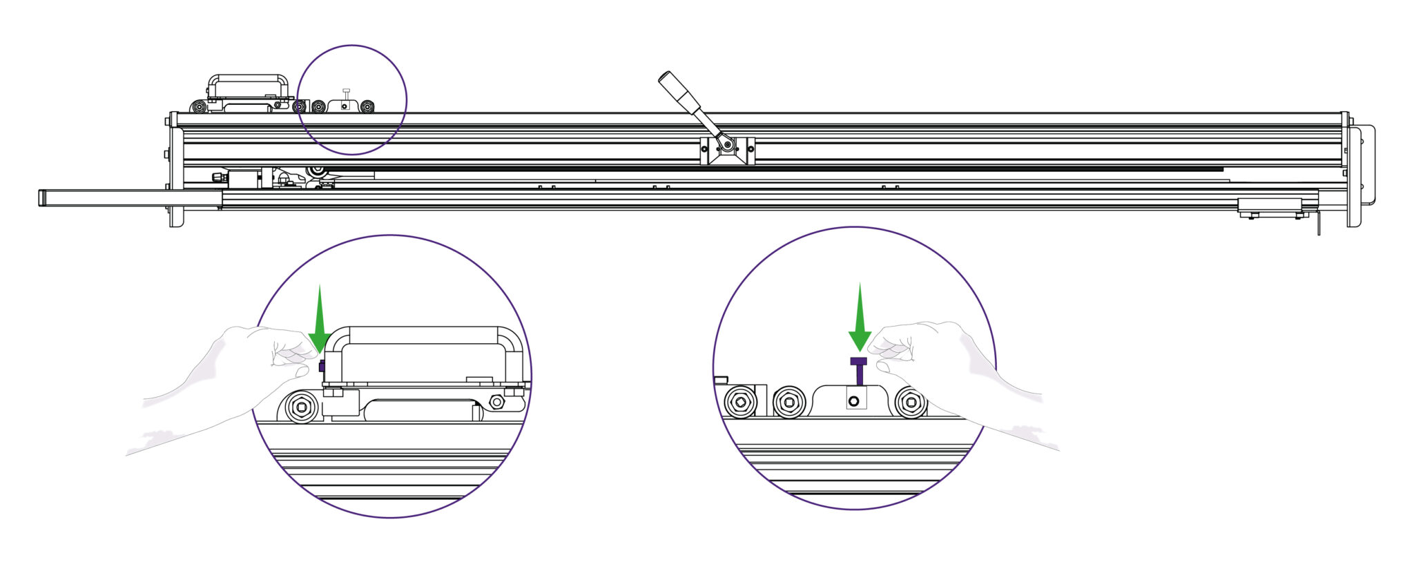
Slightly fasten the two thumbscrews (part S) into the top and bottom cutting heads as shown.
Do not firmly fasten these at this point as the cutting heads would not move otherwise, as this may be required in future steps
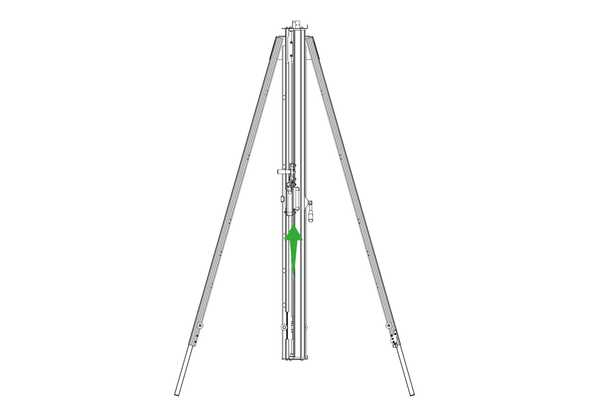
Move the lower Cutting Head to the middle of the Main Body.
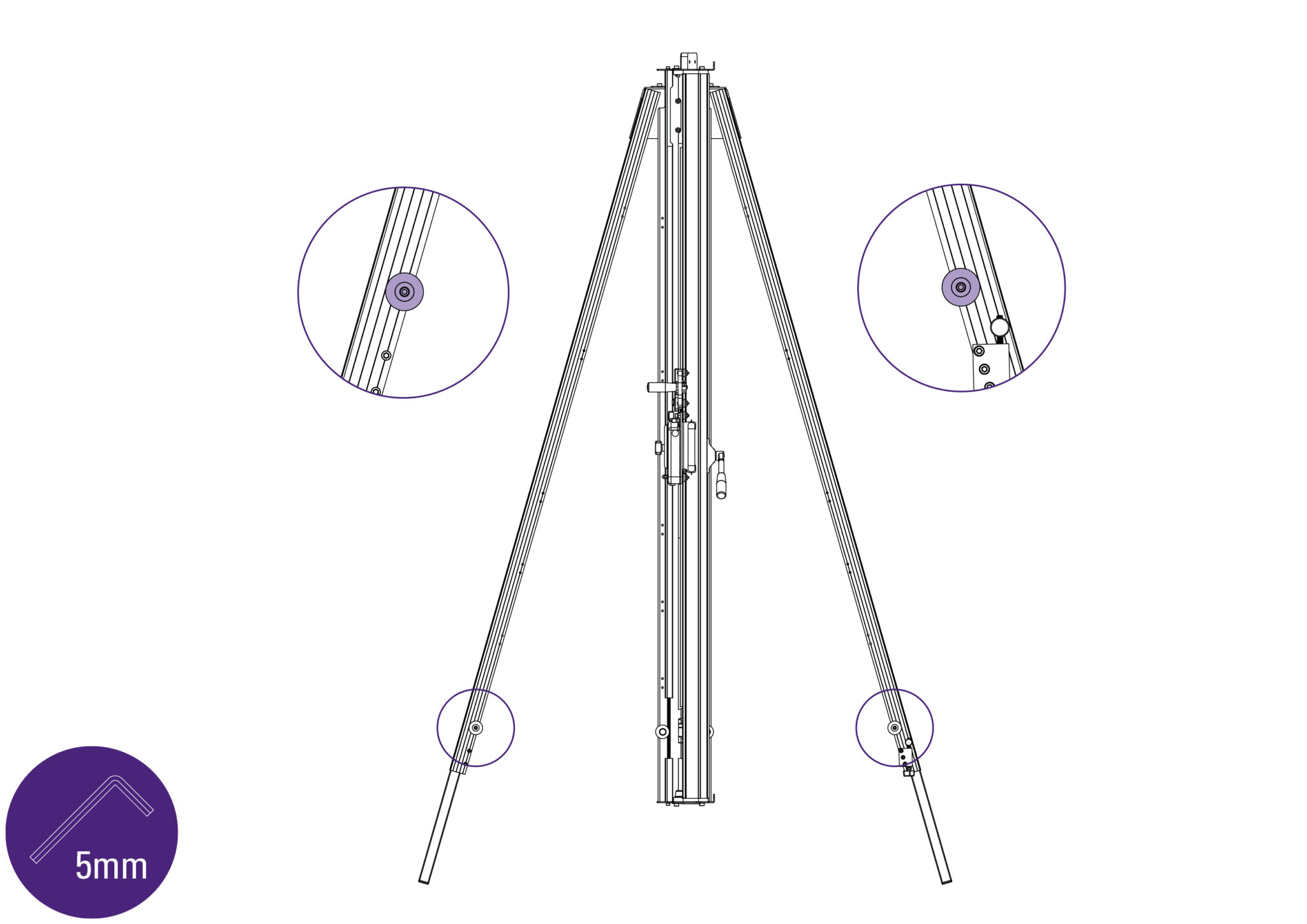
Remove the top screw (along with the washers and spacer) from each leg, using 5mm Allen (hex) key.
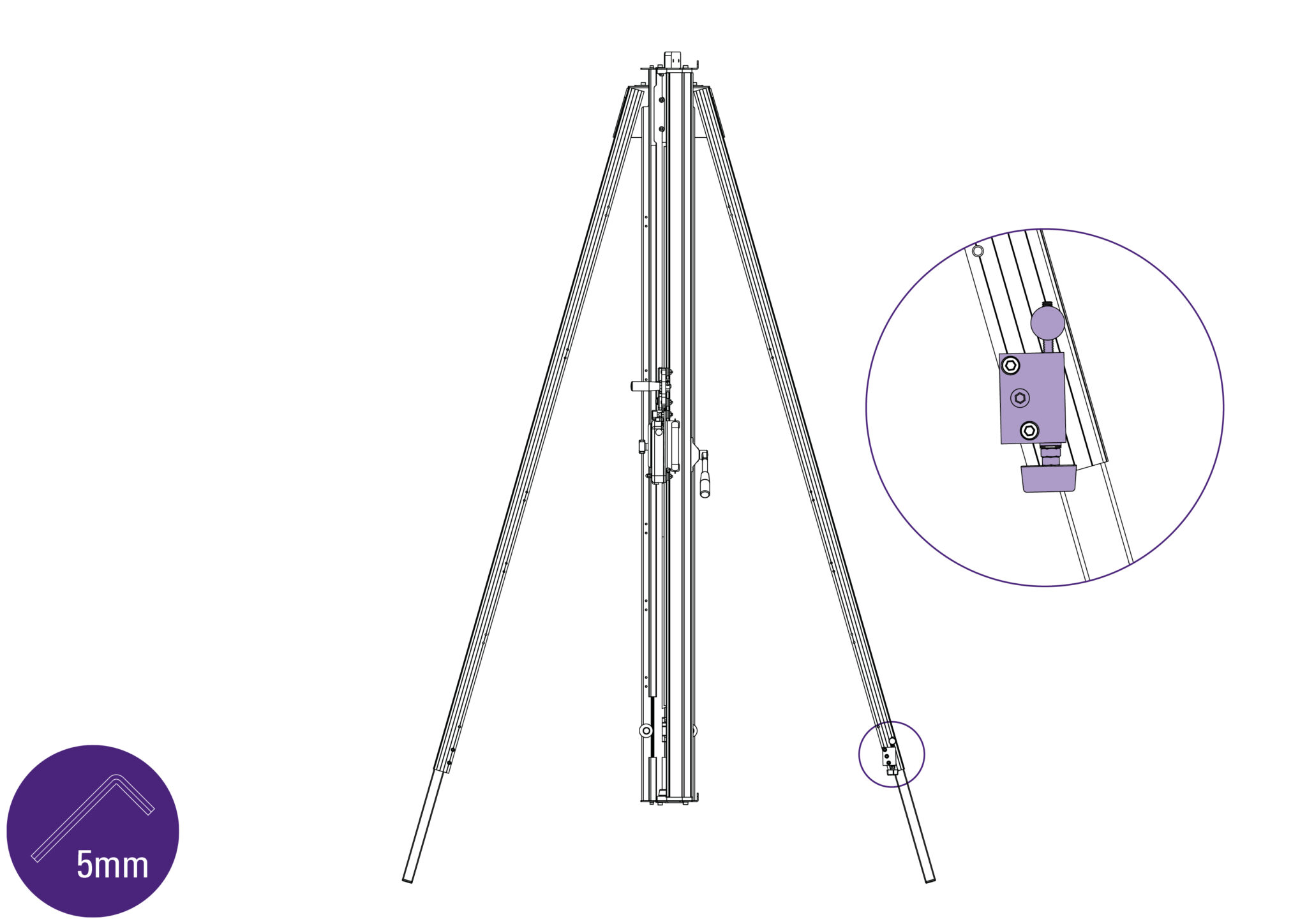
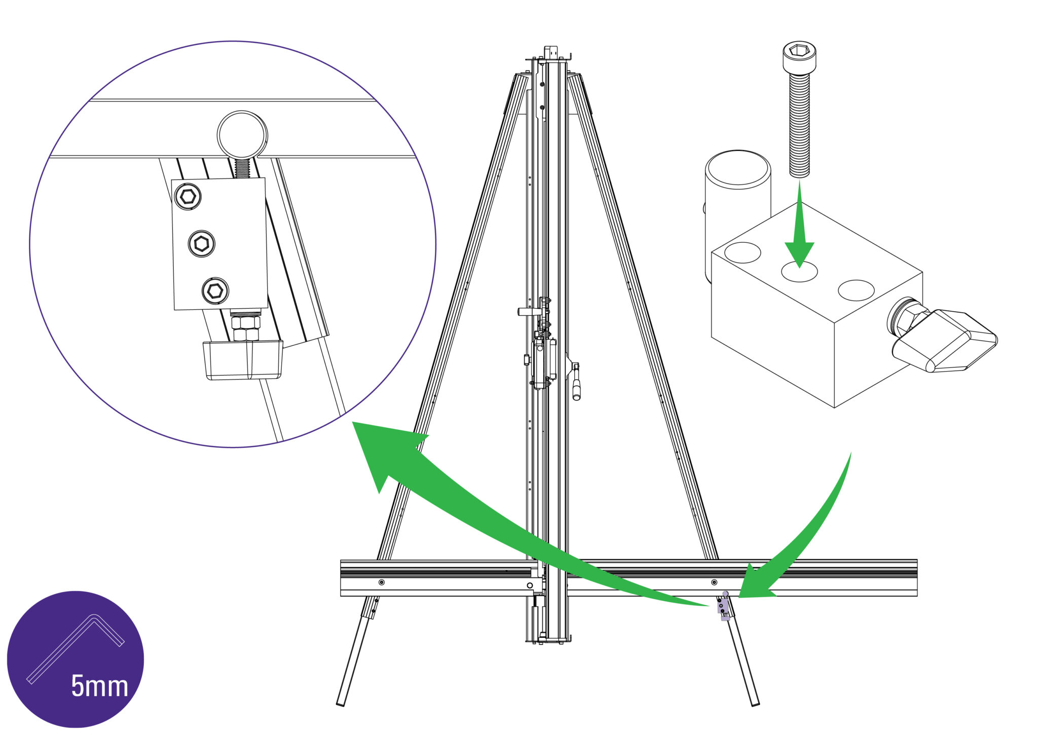
Remove the Squaring Adjuster Block from the right hand Leg by releasing the middle screw only.
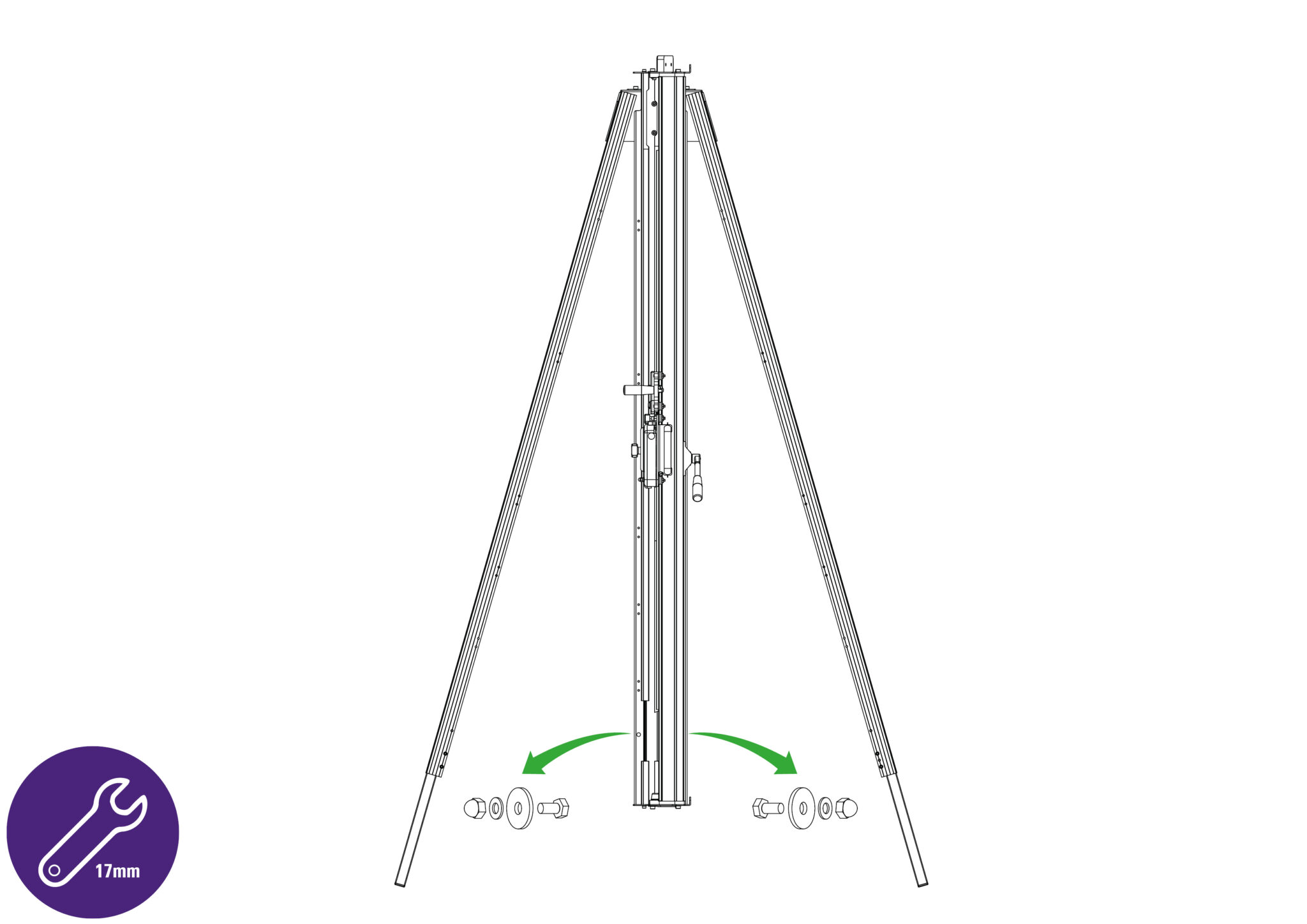
Remove two sets of hexagon headed bolts, spacers, washers and nuts from the Main Body using a 17mm spanner (wrench).
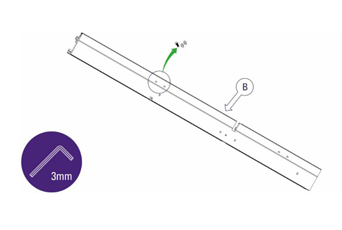
Remove small screw and two washers from the back of the Squaring Arm (part B) using the 3mm Allen (hex) key.
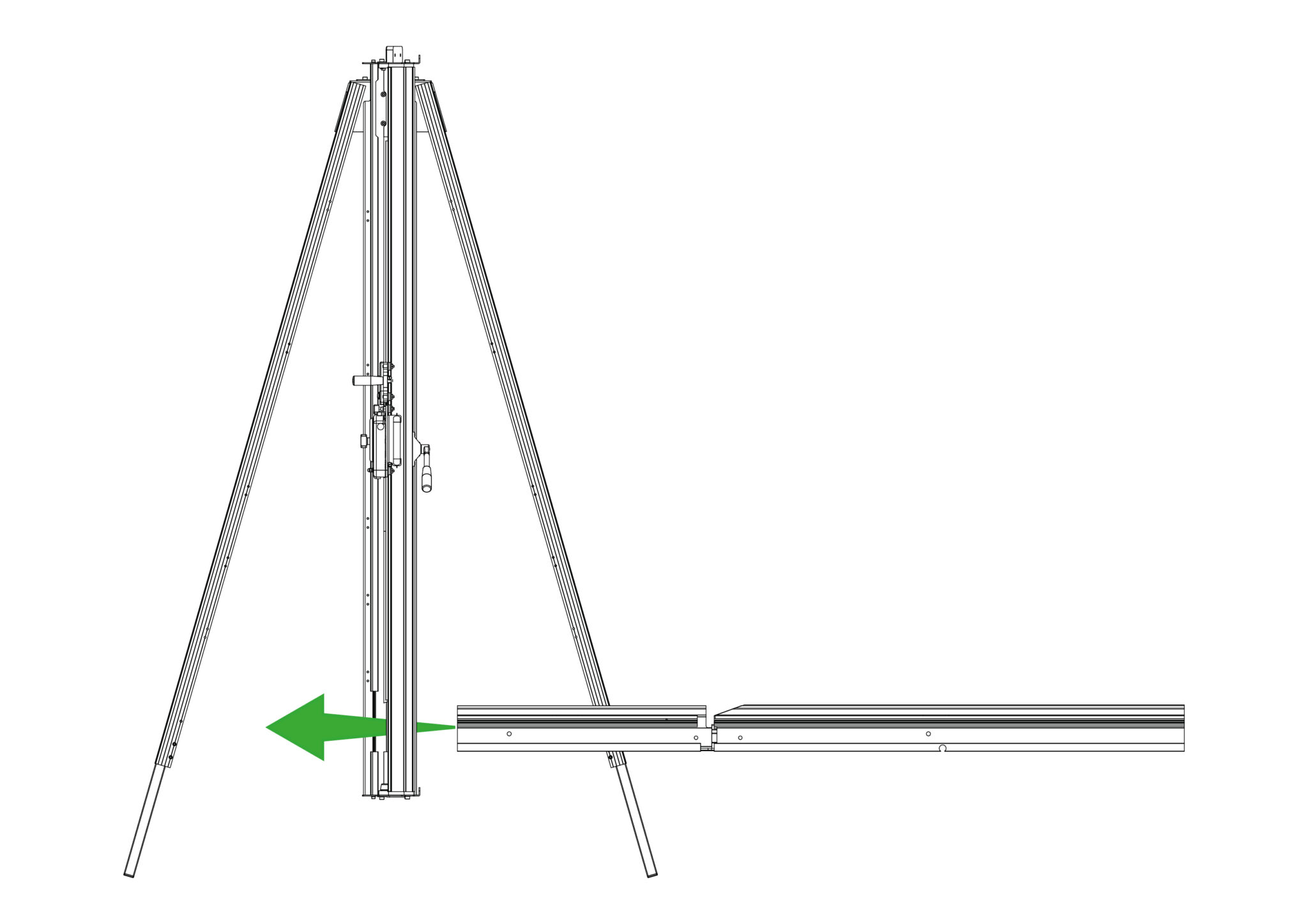
Slide the Squaring Arm in from the right hand side through the gap in the Main Body and align the corresponding screw holes between the Squaring Arm and the Main Body.
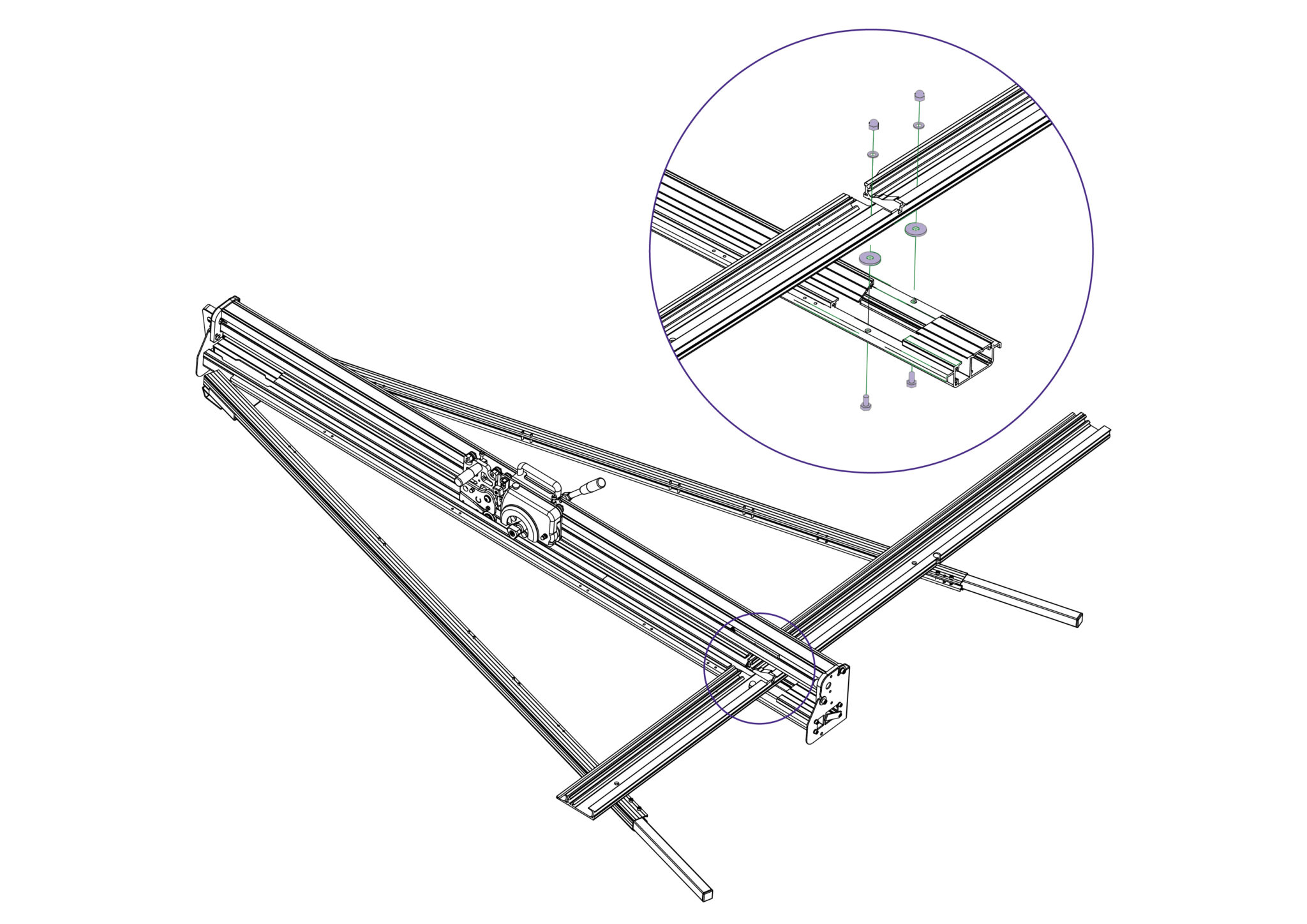
Slightly raise the Squaring Arm to place one spacer in between the Main Body and the Squaring Arm on each central hole.
Fit the two hexagon bolts from the back of the Main Body through the spacer and Squaring Arm.
Fit the washers and nuts from the front, but finger tight only.
| Do this gently |
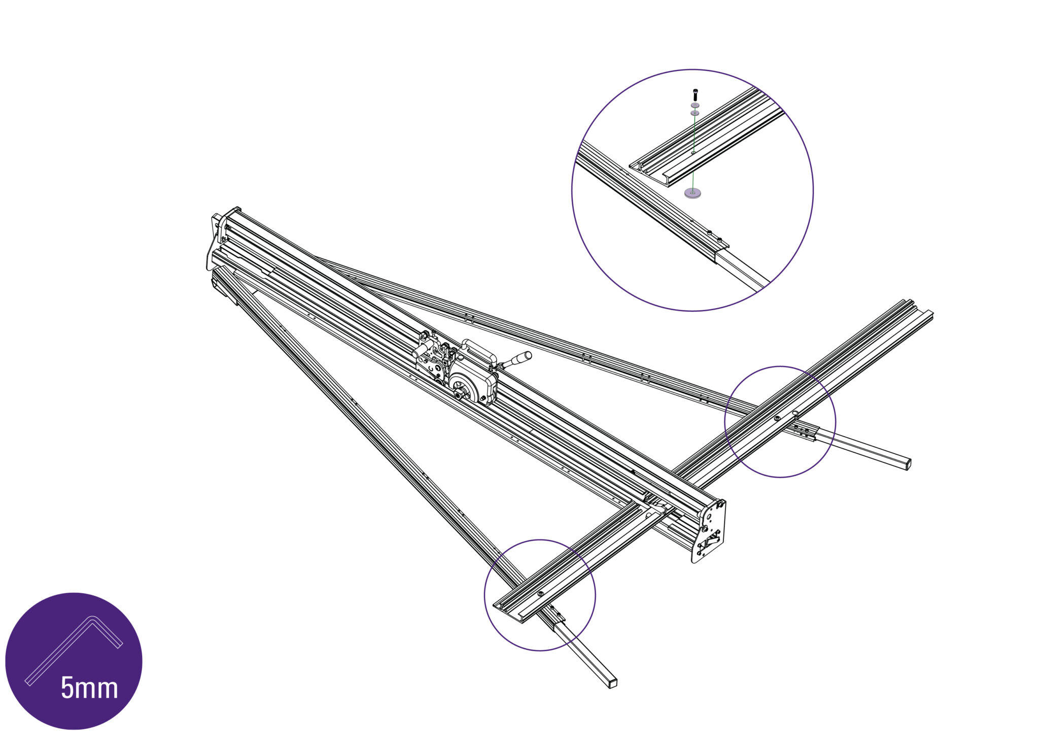
Place one spacer in between each leg and the Squaring Arm.
Fit the screws through the Squaring Arm and into each leg using the 5mm Allen (hex) key, but do not tighten fully.
| Do this gently |
Refit the squaring adjuster block by firstly sliding the steel bar into the opening in the Squaring Arm, then align the heads of the two screws in the leg to fit the top and bottom holes in the adjuster block.
The screws fixing the Squaring Arm to the machine should still be loose and allow it some movement to help alignment.
Insert and tighten the screw in the middle hole.
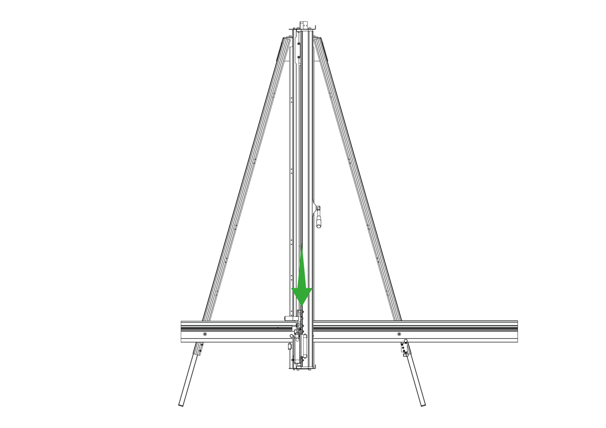
Move the Cutting Head to its lowest position.
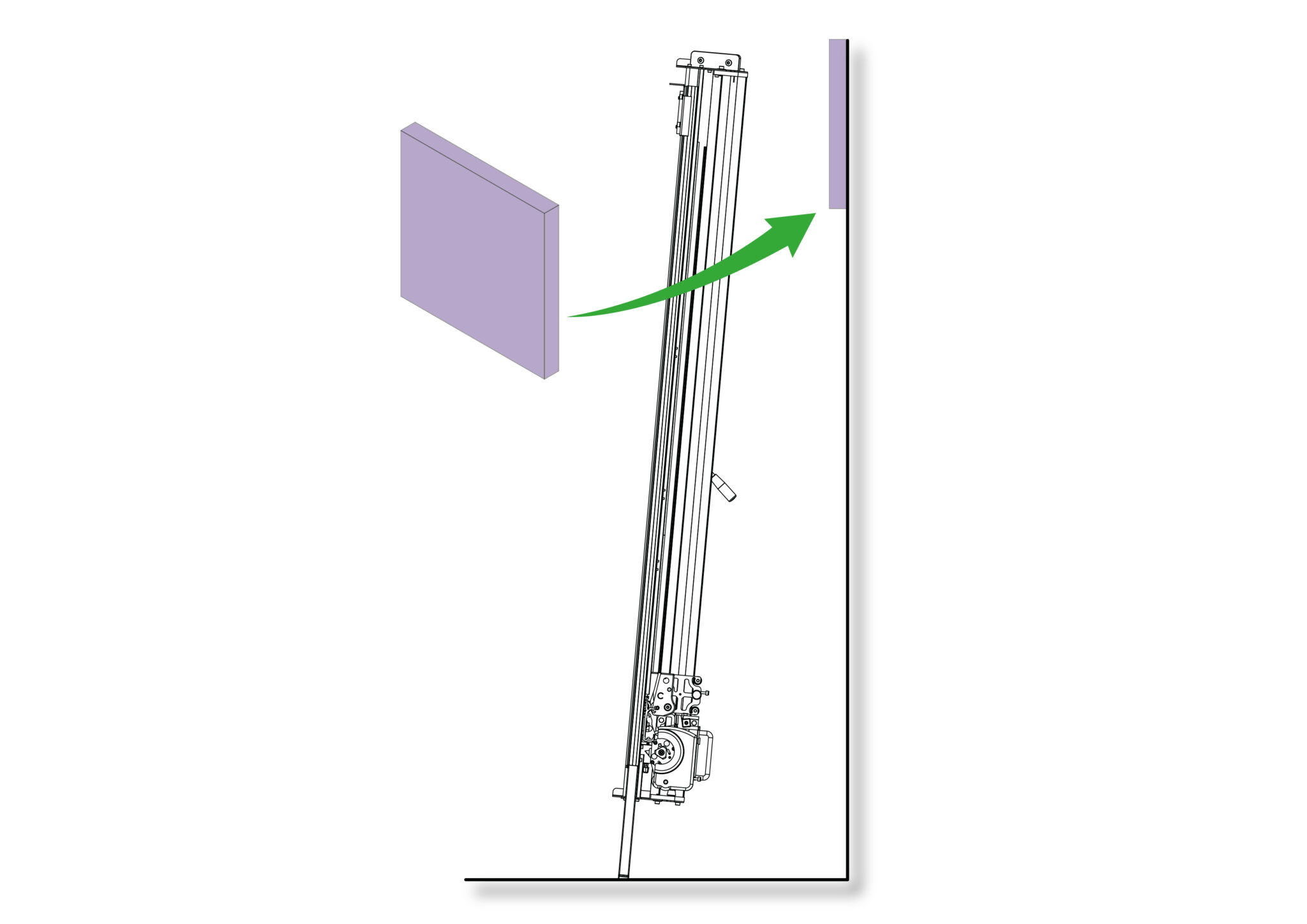
Get help to slowly lift the machine and lean it so that the front faces towards the wall. If the machine is too high or too low, bring the machine back down and refer back to Adjusting the legs> to adjust the machine height.
If the height is satisfactory, carefully place a scrap of card or board in between the top end of the machine and the wall to prevent any damage.
| Be careful when lifting |
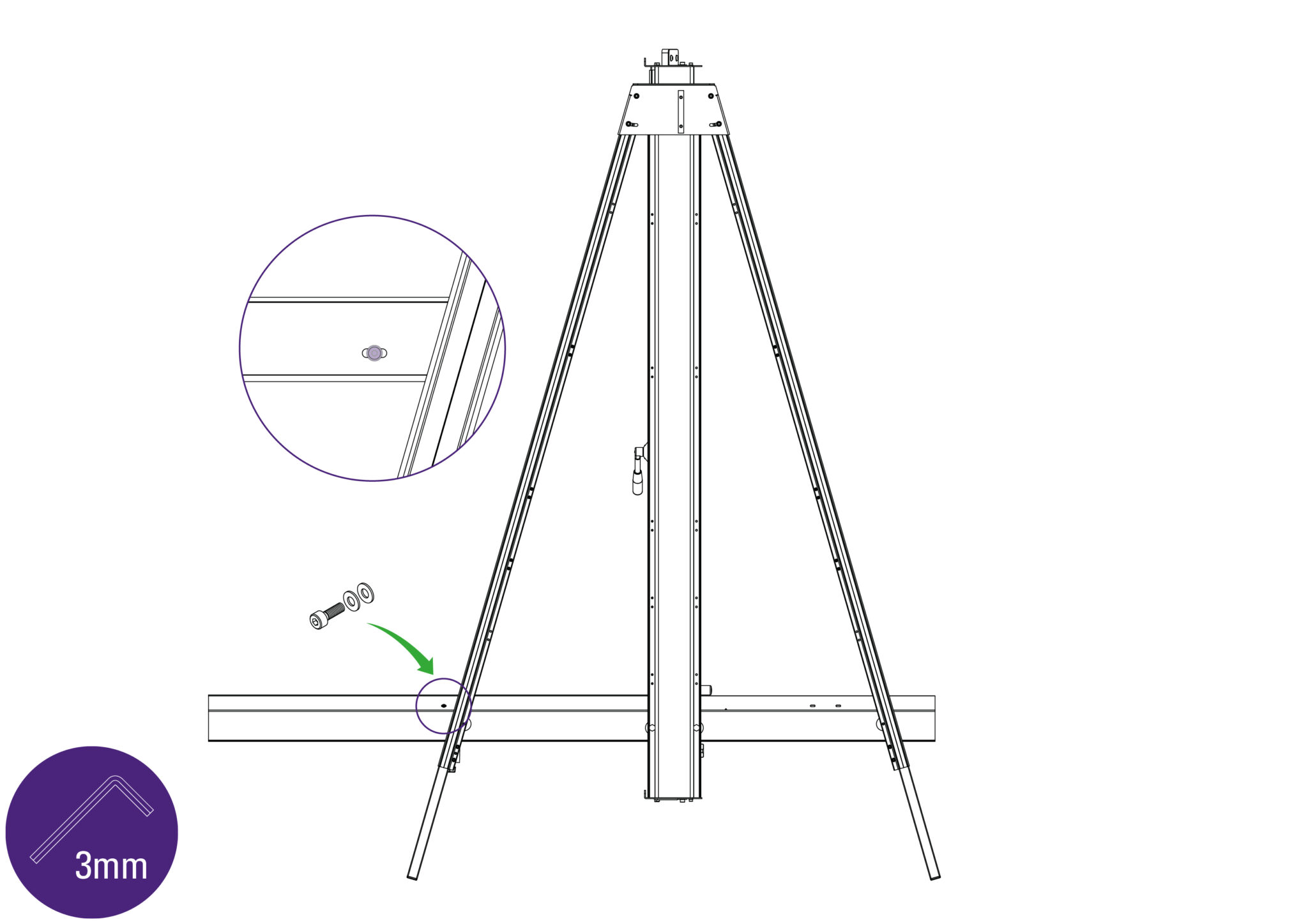
Re-fasten the screw and two washers in the Squaring Arm using the 3mm Allen (hex) key.
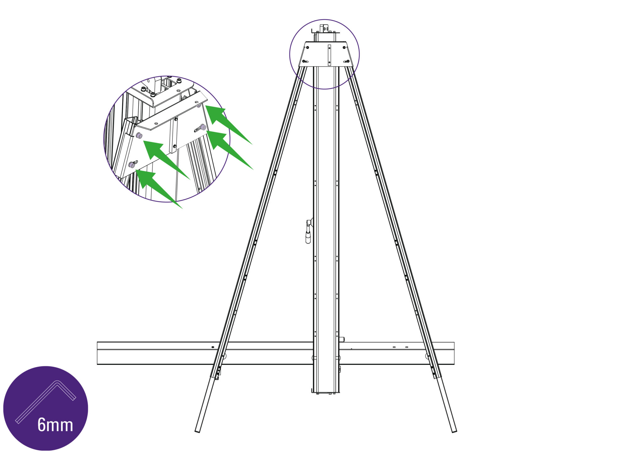
Tighten the four screws fully using the 6mm Allen (hex) key to secure the legs at the top of the Main Body.
| Do this firmly |
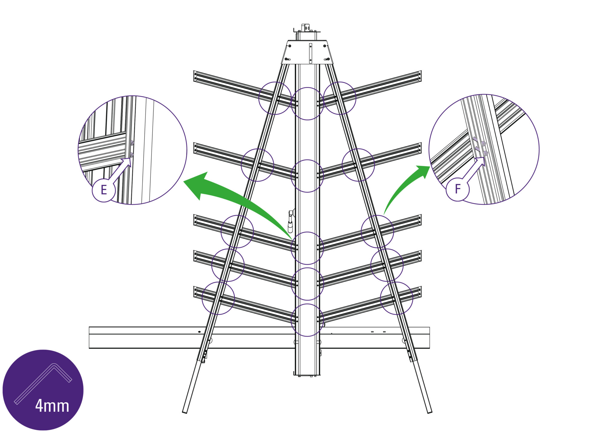
Use one of the short screws (part F) to fix the support arm to the main body, and one of the long screws (part E) in each of the holes along the legs of the machine. Ensure the ends of the supports are firmly against the Main Body and the screws are aligned with the special grooves as explained above.
If a free standing kit is to be fitted to the machine, proceed directly to Fitting the optional free standing kit >
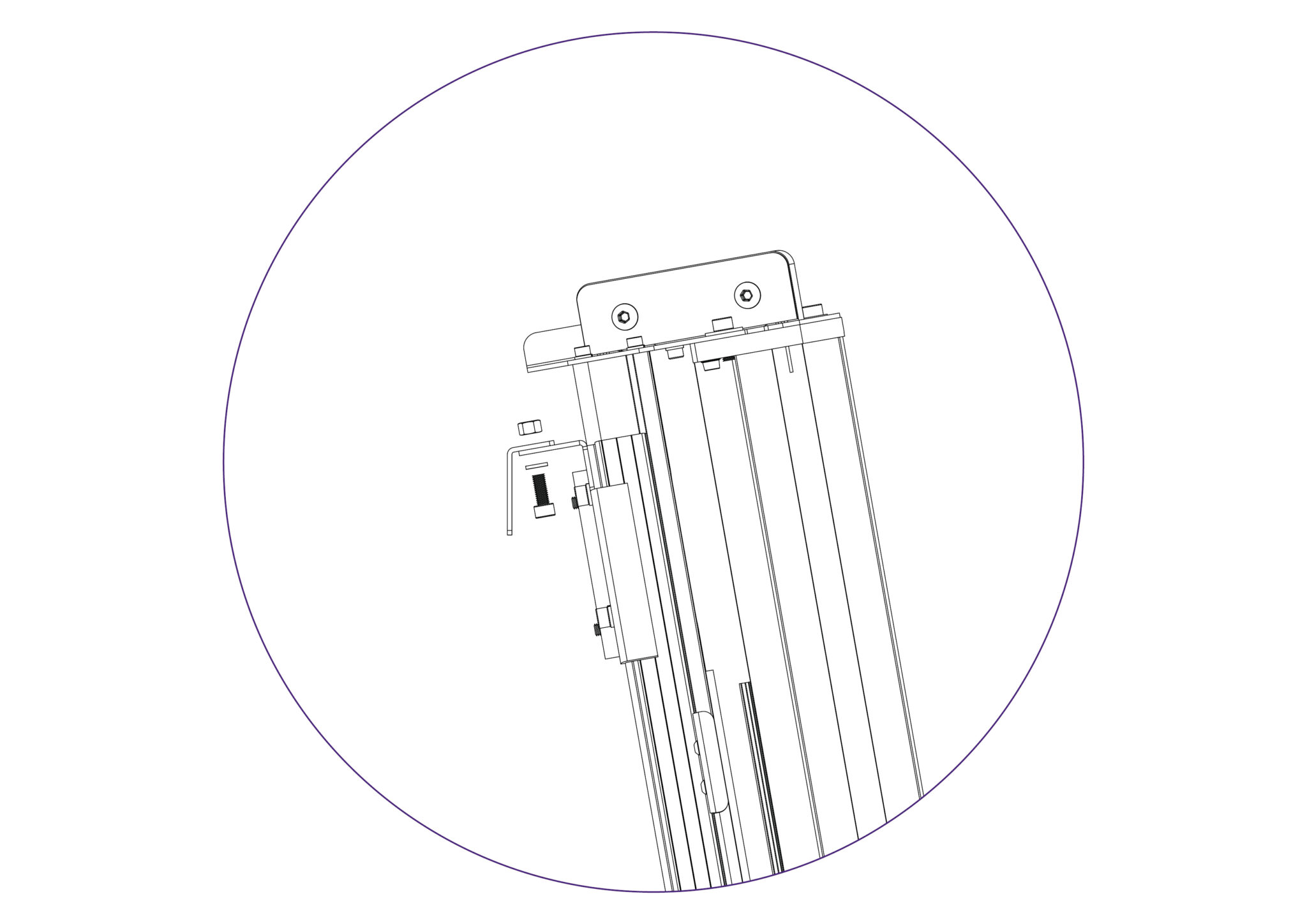
Fit the Wall Mounting Bracket to the top of the Main Body, and fasten the screws finger tight only.
| Do this gently |
NOTE: If a free standing kit is to be fitted to the machine, proceed directly to Fitting the optional free standing kit >
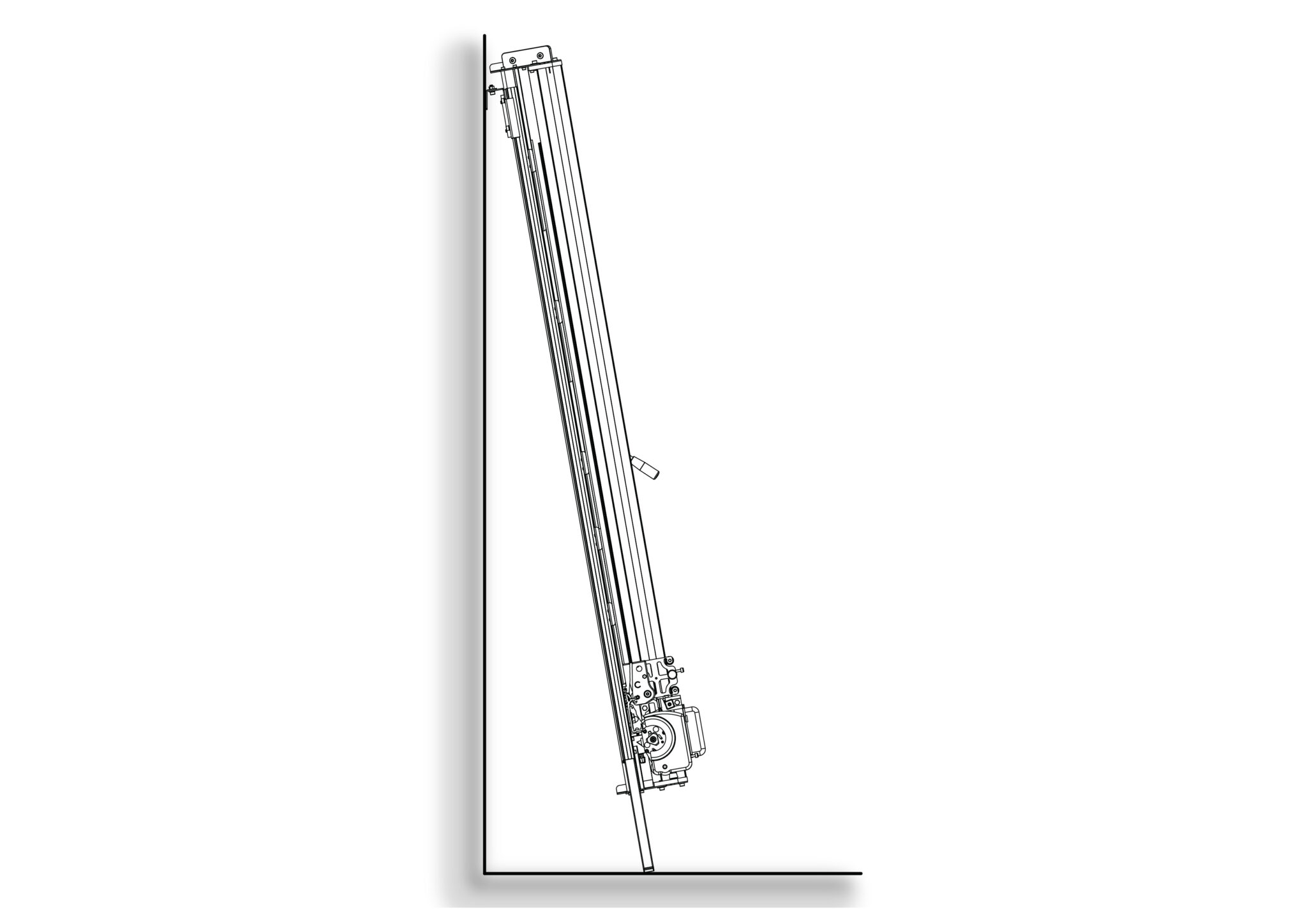
Stand the machine vertical and turn it around so that the machine is now facing away from the wall.
| Be careful when lifting |
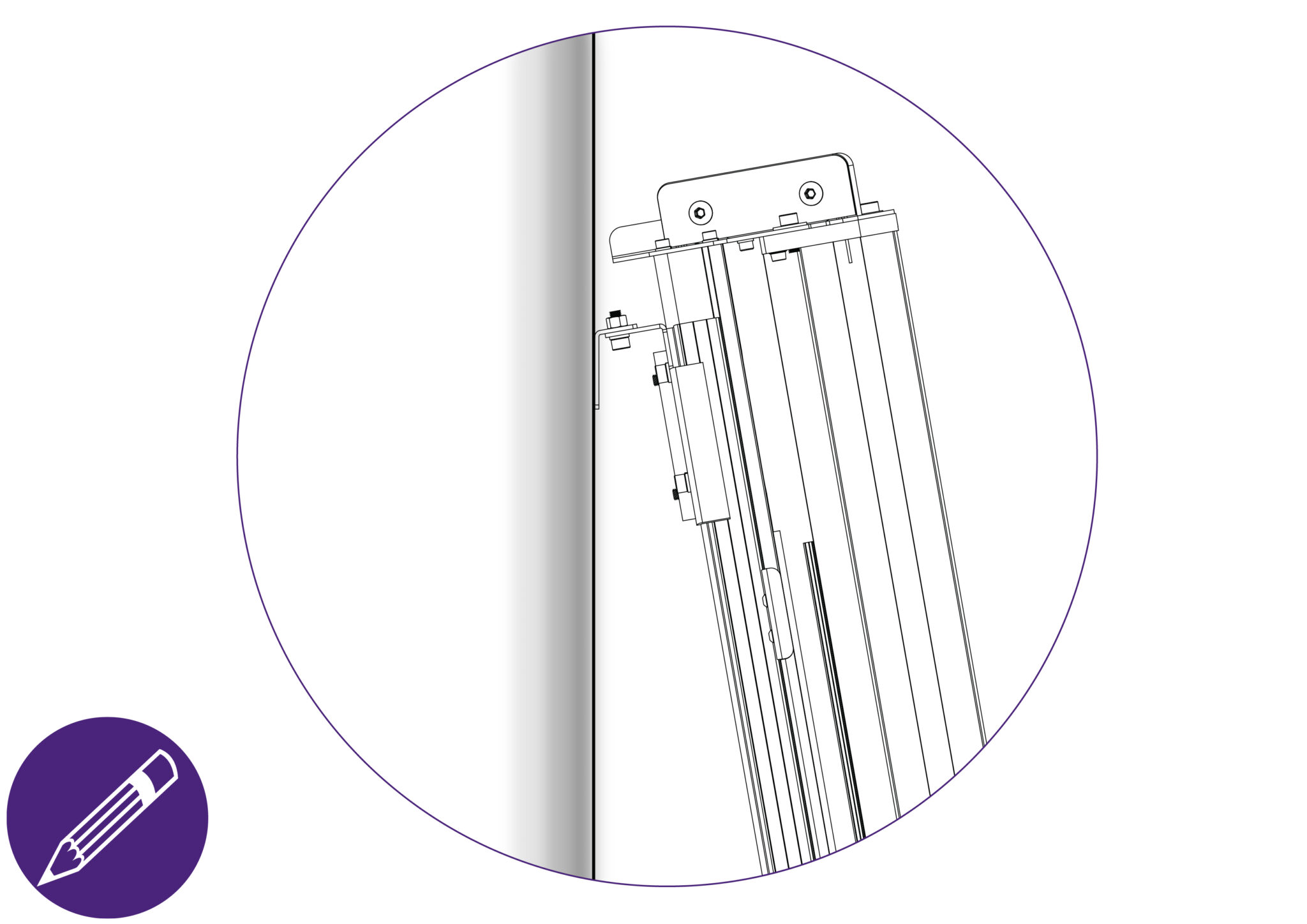
The Wall Mounting Bracket should lay flush against the wall. Mark the position of the wall fixings with a short pencil.
Move the machine away and remove the Wall Mounting Bracket.
| Be careful when lifting |
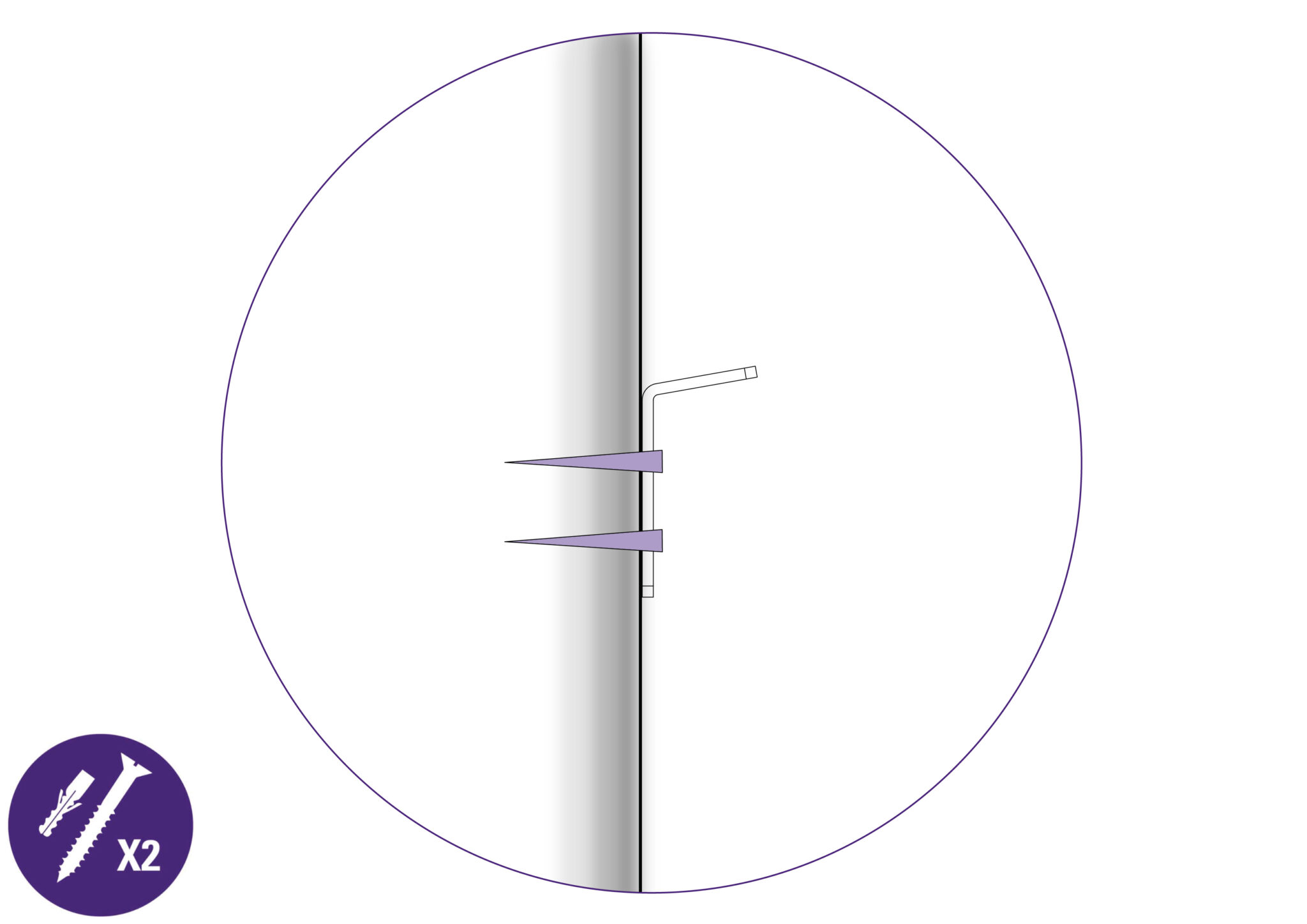
Attach the Bracket to the wall in the marked position with appropriate fixings then reposition and fasten the machine to the bracket.
Proceed to Checking the machine for squareness >
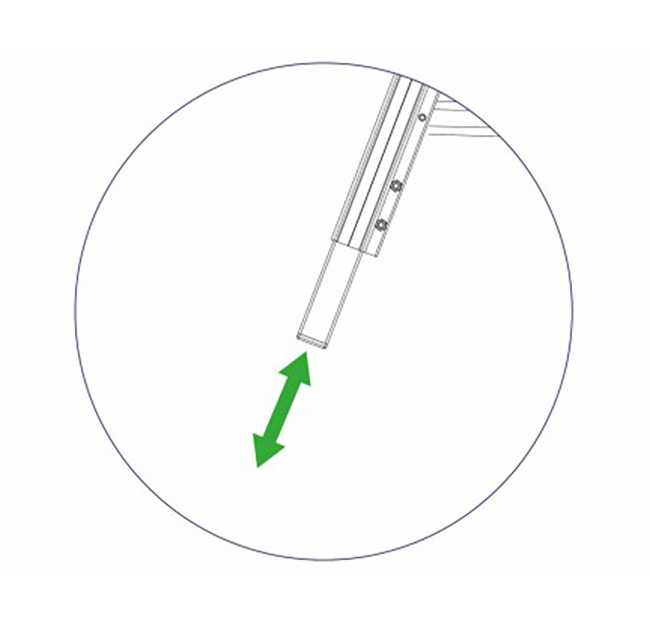
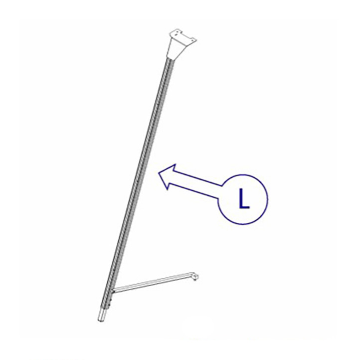
Extend the telescopic leg to the desired length such that it levels with the extension of the front two legs.
Assistance will be needed for the following stages
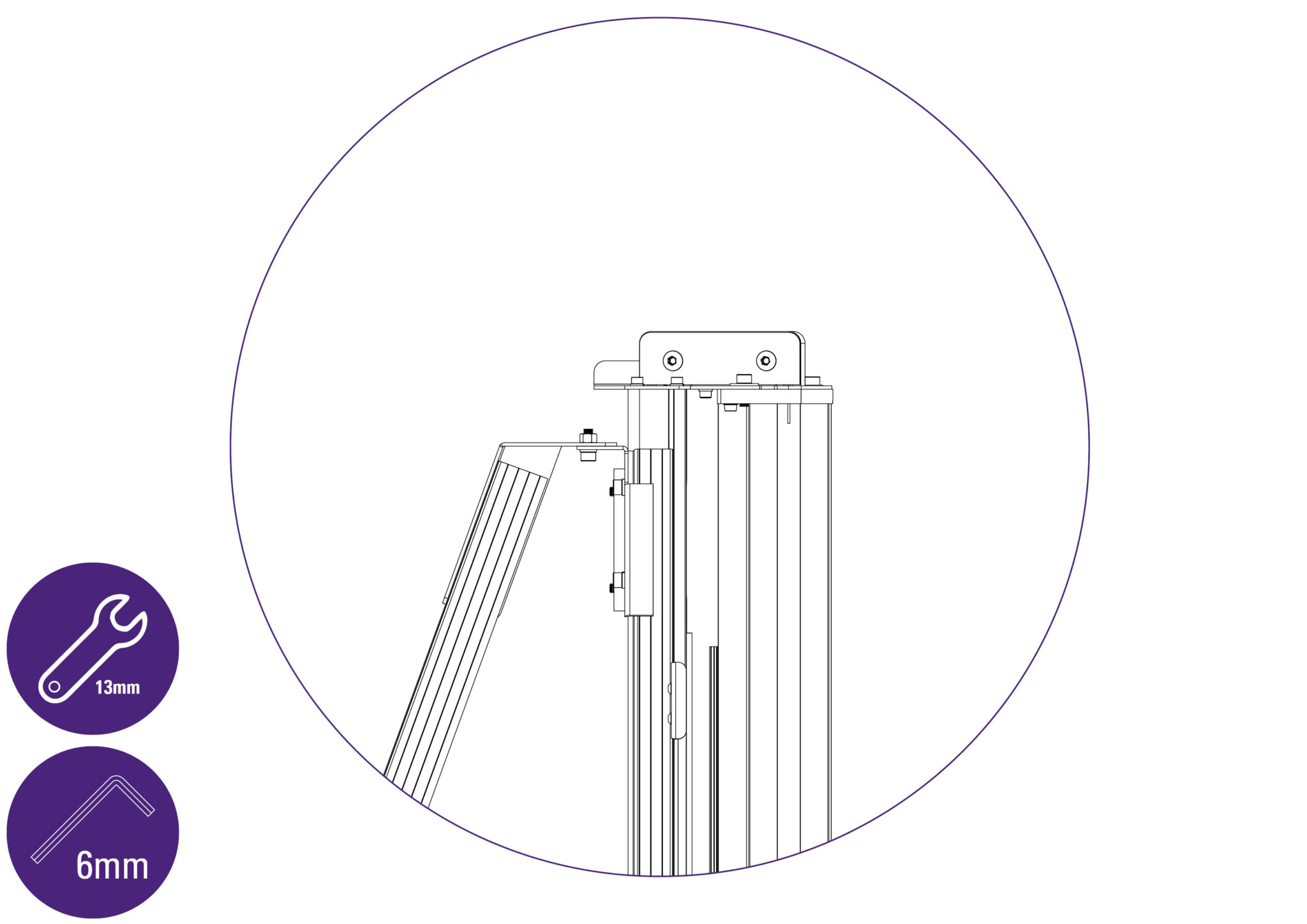
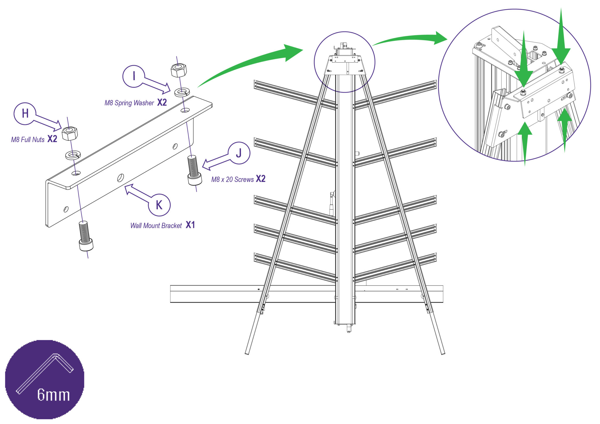
Get help to stand the machine up and hold it while the free standing leg is fixed to the bracket using the 6mm Allen (hex) key and 13mm spanner (wrench). The nuts and screws (Parts H, I, and J) are provided with the main machine.
| Do this firmly |
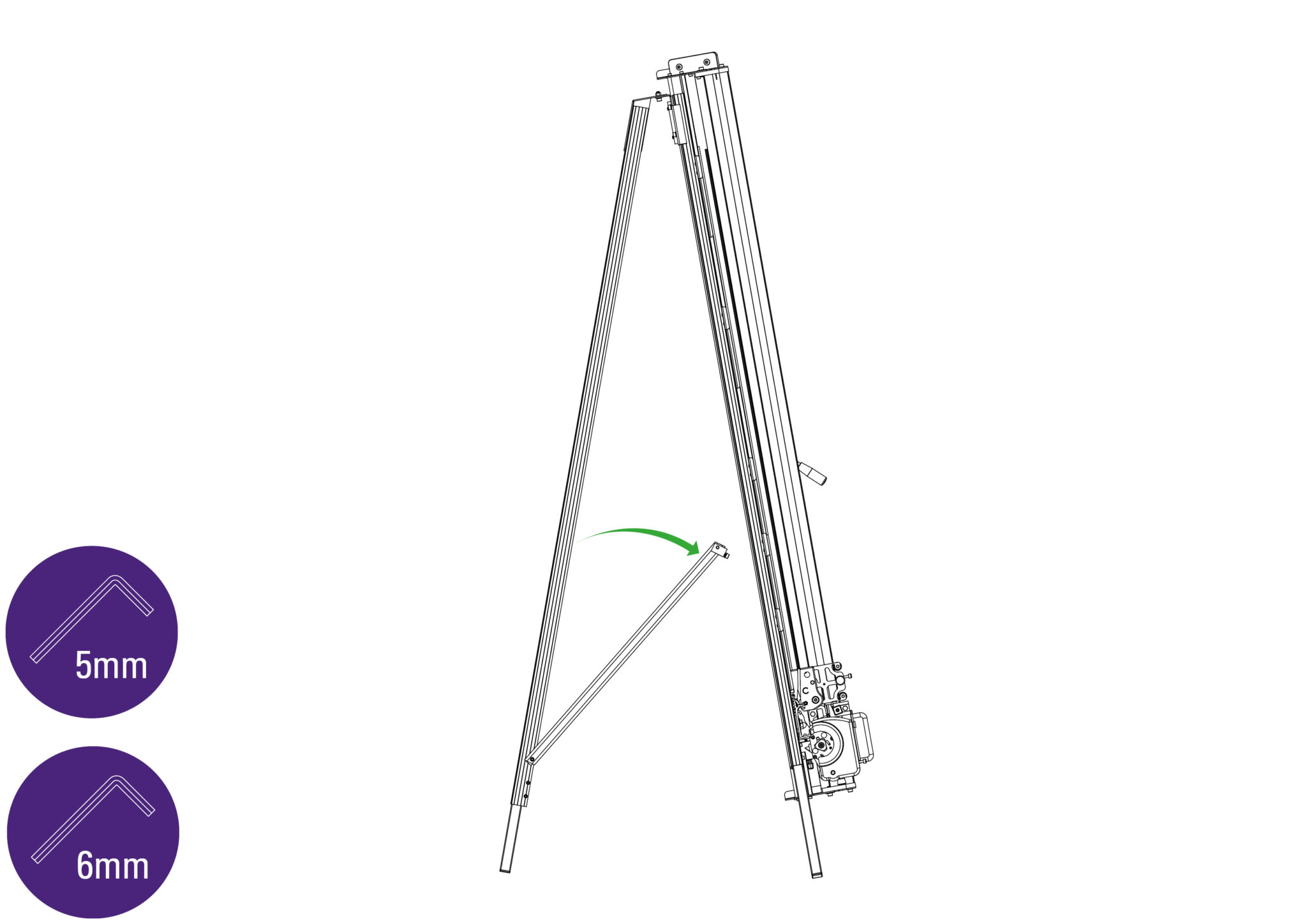
Swing down the stay and attach the fixing block to the back of the main body. Tighten all three screws on the stay (using the 5mm & 6mm Allen (hex) keys).
Extend the telescopic leg so the machine stands evenly.
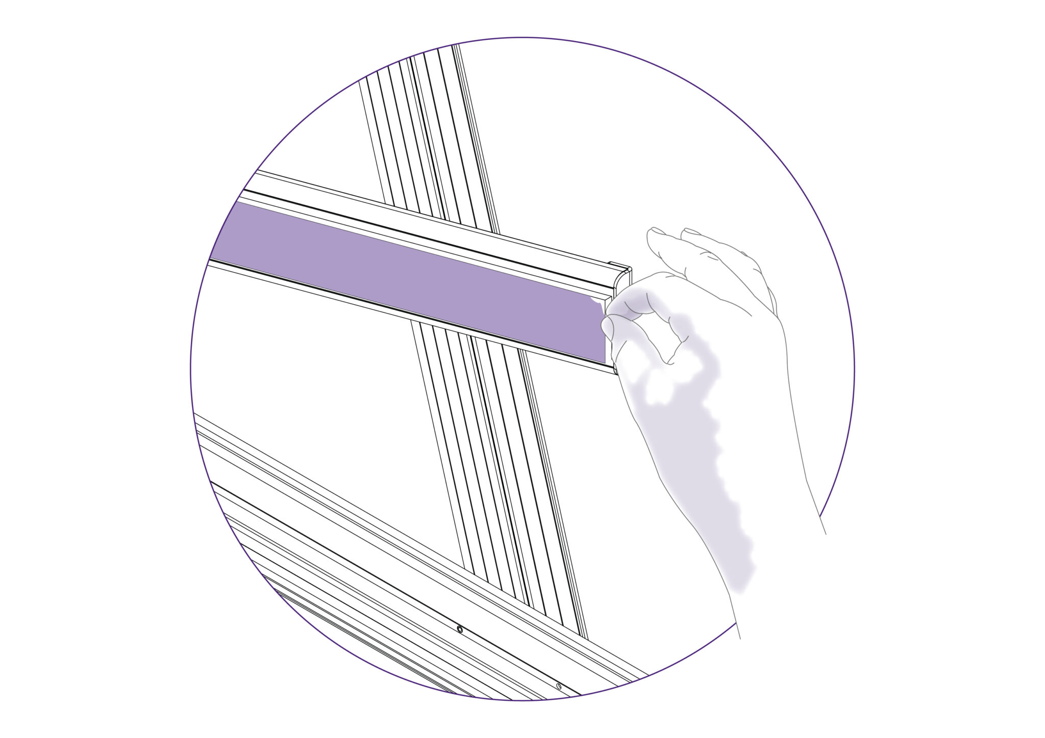
Remove the protective film from all the blue support strips. This is to be done on all the five Support Arm strips.
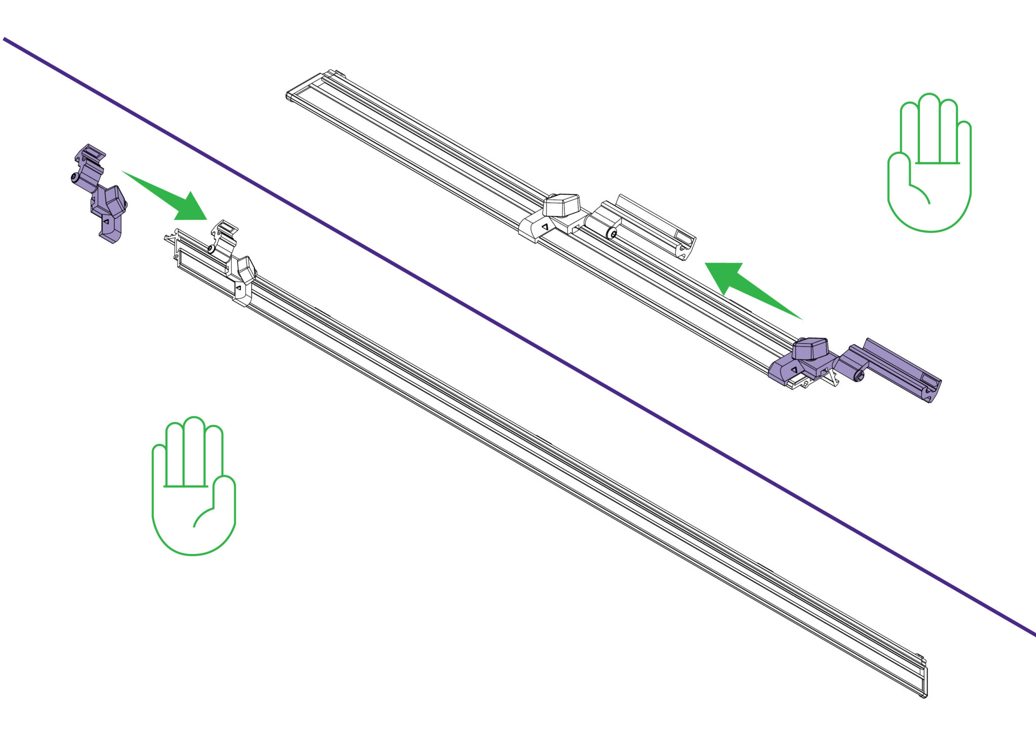
Slide the measuring stops on to the left and right hand Easy Measuring Scales.
  |
Left hand side |
  |
Right hand side |
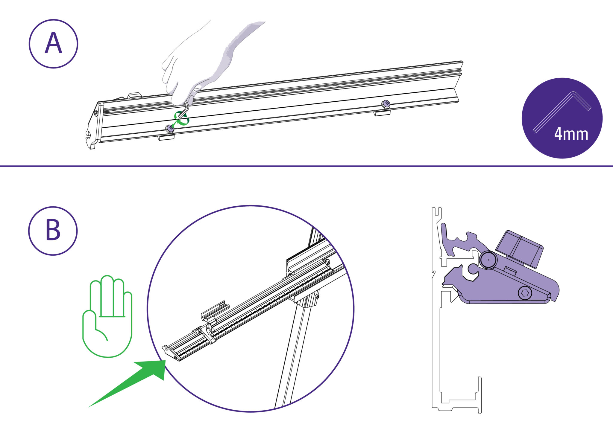
A) Loosen the two screws so the fixing blocks allow the Easy Measuring Scale to slide onto the squaring arm.
B) Ensure the end cap is flush with end of the squaring arm and tighten the two fixing screws using a 4mm Allen (Hex) key.
| Do this firmly |
|
Left hand side |
Repeat the process on the right hand side.
Slacken the bottom two screws on each leg using the 5mm Allen (hex) key and extend the
telescopic parts equally to the desired length.
Re-tighten screws firmly to clamp legs in position.
Swing both legs outwards as far as they will go.
Align the handle (part P) with the cutting head’s holes and fasten the wing bolts (part Q) from the other side securely.
| Do this firmly |
Slightly fasten the two thumbscrews (part S) into the top and bottom cutting heads as shown.
Do not firmly fasten these at this point as the cutting heads would not move otherwise, as this may be required in future steps
Move the lower Cutting Head to the middle of the Main Body.
Remove the top screw (along with the washers and spacer) from each leg, using 5mm Allen (hex) key.
Remove the Squaring Adjuster Block from the right hand Leg by releasing the middle screw only.
Remove two sets of hexagon headed bolts, spacers, washers and nuts from the Main Body using a 17mm spanner (wrench).
Remove small screw and two washers from the back of the Squaring Arm (part B) using the 3mm Allen (hex) key.
Slide the Squaring Arm in from the right hand side through the gap in the Main Body and align the corresponding screw holes between the Squaring Arm and the Main Body.
Slightly raise the Squaring Arm to place one spacer in between the Main Body and the Squaring Arm on each central hole.
Fit the two hexagon bolts from the back of the Main Body through the spacer and Squaring Arm.
Fit the washers and nuts from the front, but finger tight only.
| Do this gently |
Place one spacer in between each leg and the Squaring Arm.
Fit the screws through the Squaring Arm and into each leg using the 5mm Allen (hex) key, but do not tighten fully.
| Do this gently |
Refit the squaring adjuster block by firstly sliding the steel bar into the opening in the Squaring Arm, then align the heads of the two screws in the leg to fit the top and bottom holes in the adjuster block.
The screws fixing the Squaring Arm to the machine should still be loose and allow it some movement to help alignment.
Insert and tighten the screw in the middle hole.
Move the Cutting Head to its lowest position.
Get help to slowly lift the machine and lean it so that the front faces towards the wall. If the machine is too high or too low, bring the machine back down and refer back to Adjusting the legs> to adjust the machine height.
If the height is satisfactory, carefully place a scrap of card or board in between the top end of the machine and the wall to prevent any damage.
| Be careful when lifting |
Re-fasten the screw and two washers in the Squaring Arm using the 3mm Allen (hex) key.
Tighten the four screws fully using the 6mm Allen (hex) key to secure the legs at the top of the Main Body.
| Do this firmly |
Use one of the short screws (part F) to fix the support arm to the main body, and one of the long screws (part E) in each of the holes along the legs of the machine. Ensure the ends of the supports are firmly against the Main Body and the screws are aligned with the special grooves as explained above.
If a free standing kit is to be fitted to the machine, proceed directly to Fitting the optional free standing kit >
Fit the Wall Mounting Bracket to the top of the Main Body, and fasten the screws finger tight only.
| Do this gently |
NOTE: If a free standing kit is to be fitted to the machine, proceed directly to Fitting the optional free standing kit >
Stand the machine vertical and turn it around so that the machine is now facing away from the wall.
| Be careful when lifting |
The Wall Mounting Bracket should lay flush against the wall. Mark the position of the wall fixings with a short pencil.
Move the machine away and remove the Wall Mounting Bracket.
| Be careful when lifting |
Attach the Bracket to the wall in the marked position with appropriate fixings then reposition and fasten the machine to the bracket.
Proceed to Checking the machine for squareness >
Extend the telescopic leg to the desired length such that it levels with the extension of the front two legs.
Assistance will be needed for the following stages
Get help to stand the machine up and hold it while the free standing leg is fixed to the bracket using the 6mm Allen (hex) key and 13mm spanner (wrench). The nuts and screws (Parts H, I, and J) are provided with the main machine.
| Do this firmly |
Swing down the stay and attach the fixing block to the back of the main body. Tighten all three screws on the stay (using the 5mm & 6mm Allen (hex) keys).
Extend the telescopic leg so the machine stands evenly.
Remove the protective film from all the blue support strips. This is to be done on all the five Support Arm strips.
Slide the measuring stops on to the left and right hand Easy Measuring Scales.
|
Left hand side |
|
Right hand side |
A) Loosen the two screws so the fixing blocks allow the Easy Measuring Scale to slide onto the squaring arm.
B) Ensure the end cap is flush with end of the squaring arm and tighten the two fixing screws using a 4mm Allen (Hex) key.
| Do this firmly |
|
Left hand side |
Repeat the process on the right hand side.
Ⓒ Keencut 2020 | Baird Rd, Corby NN17 5ZA United Kingdom | Contact us
Created by DeType | Privacy | Website Disclaimer | Terms & Conditions