

Excalibur 6000 installation manual
How to use this guide
Scroll down to view the guide.
You can expand and collapse sections using the + and – icons.
The images in this manual are expandable. Click/tap on them to enlarge.
View PDF version >
Other support resources
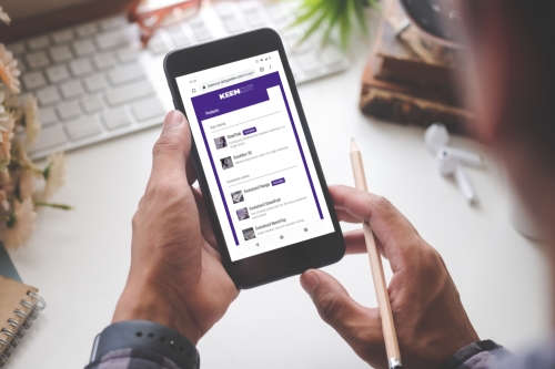
Register your cutter to activate your guarantee >
Visit Keencut support centre >
Visit user forum >
Installation video >
Contact Keencut >
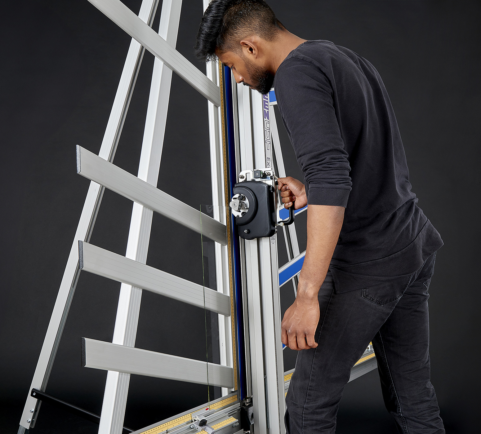
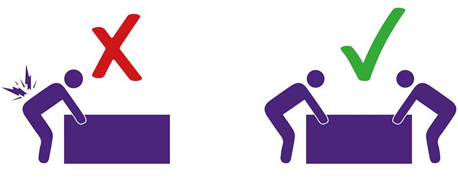
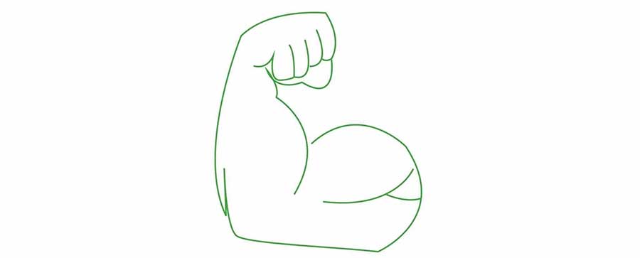
To prevent injury and damage, lift the box and the machine with 2 people.
NOTE: When lifting the main body from the box, DO NOT lift using the black handles on the cutters.
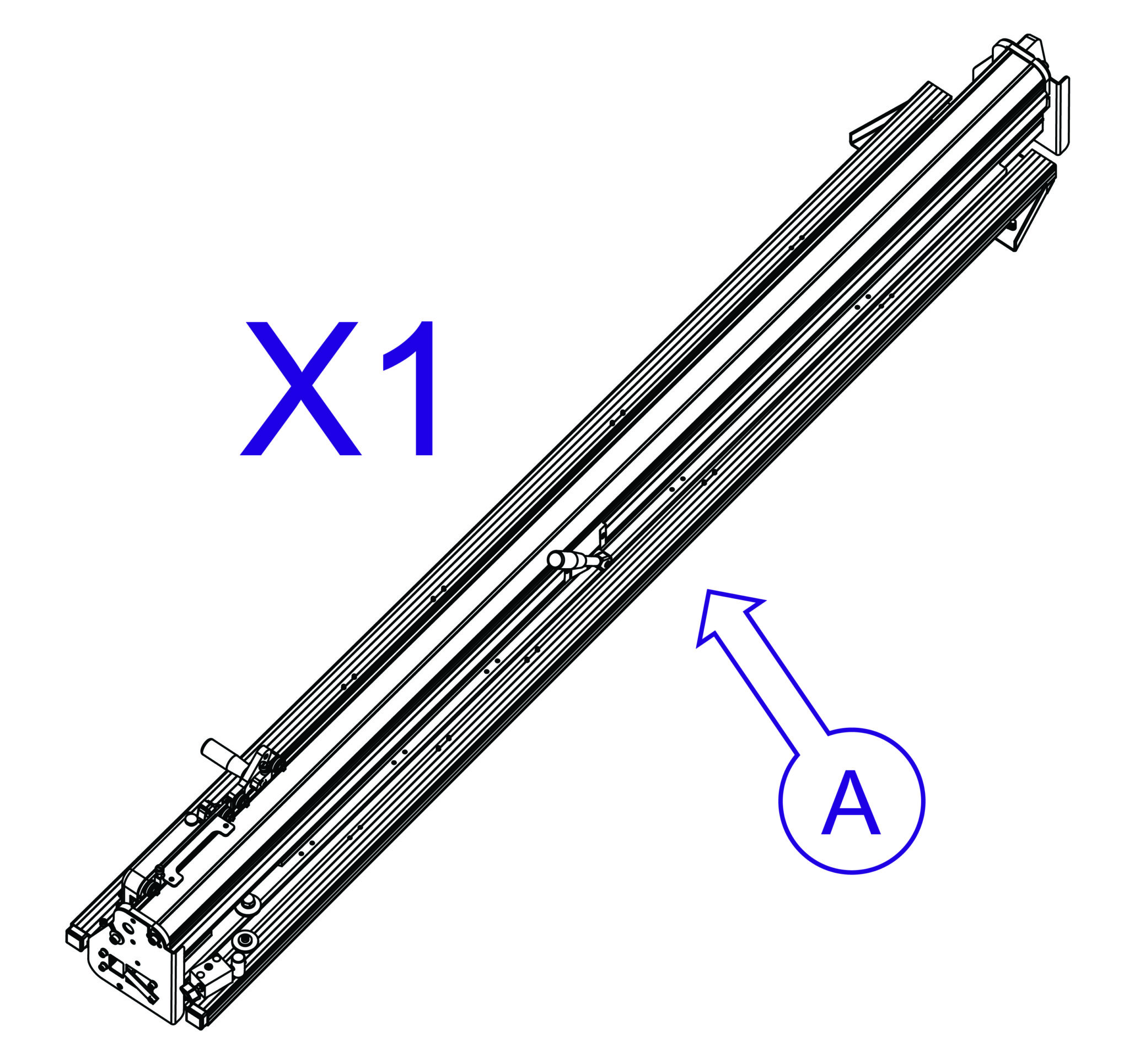
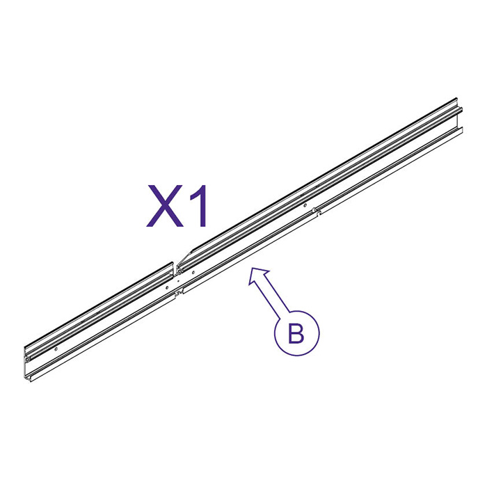
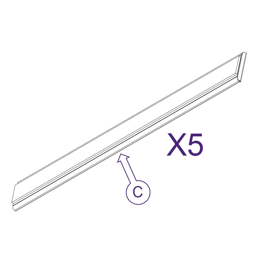
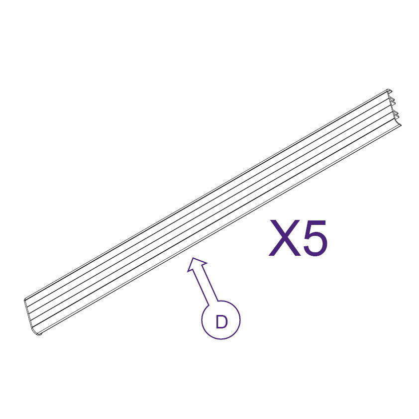
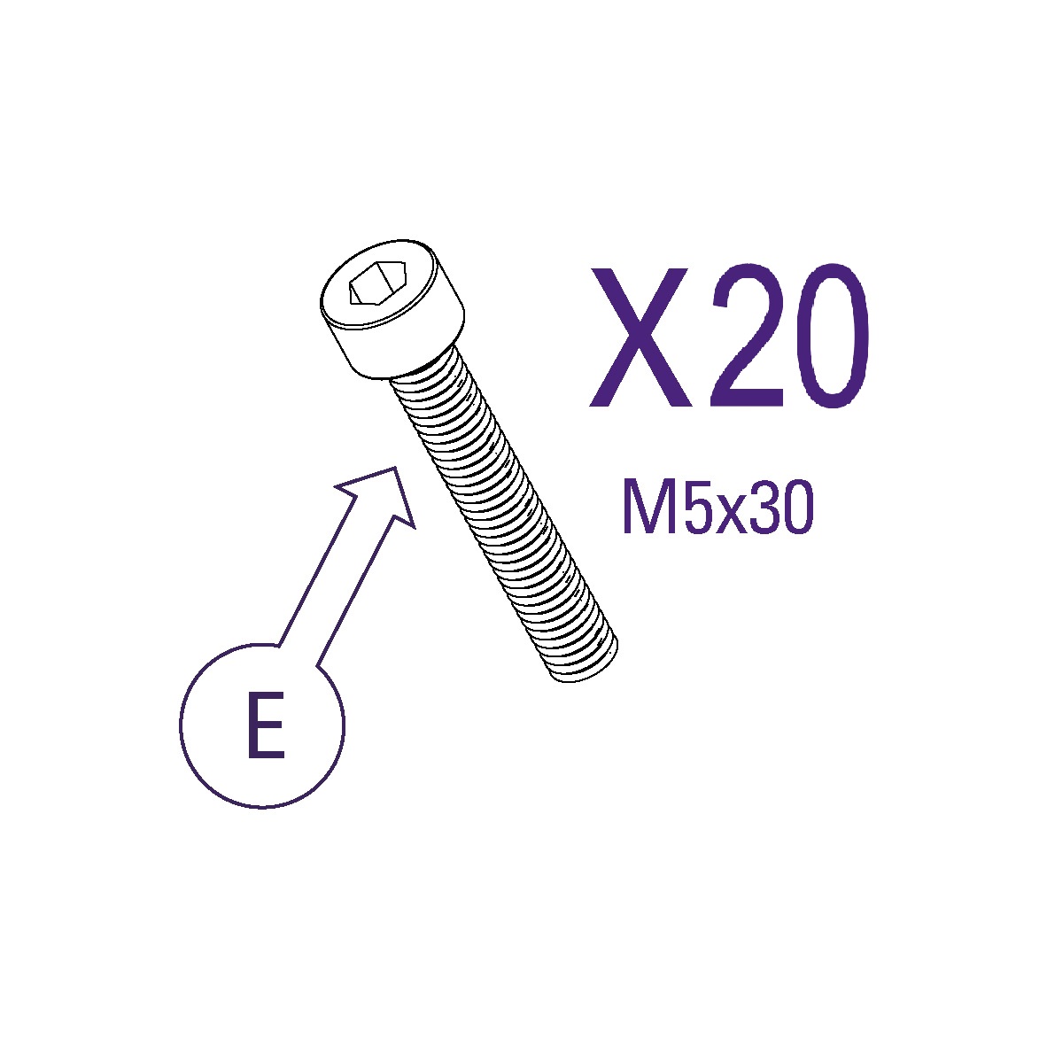
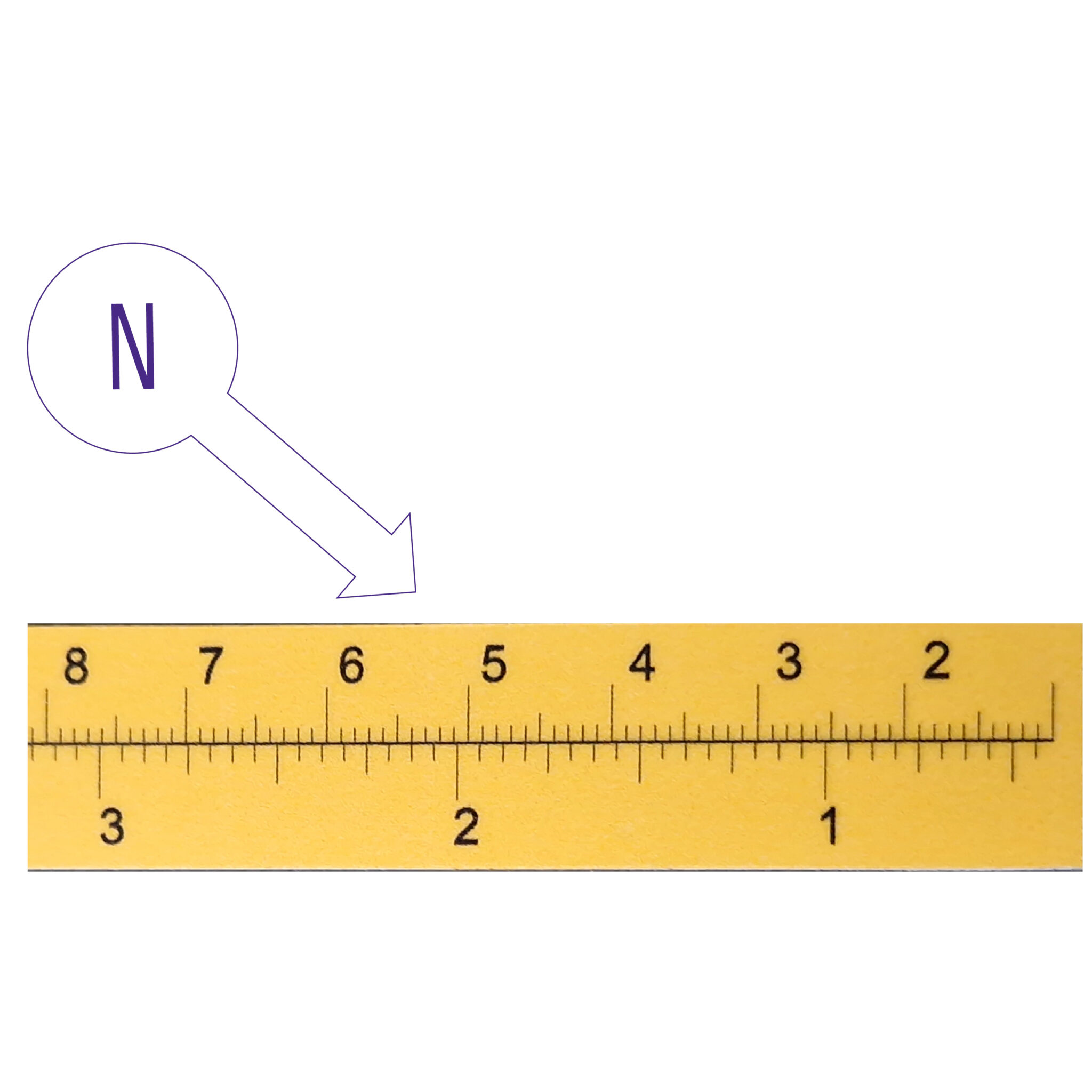
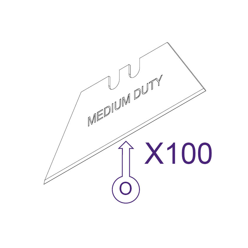
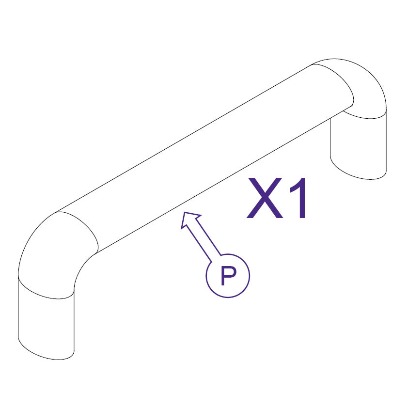
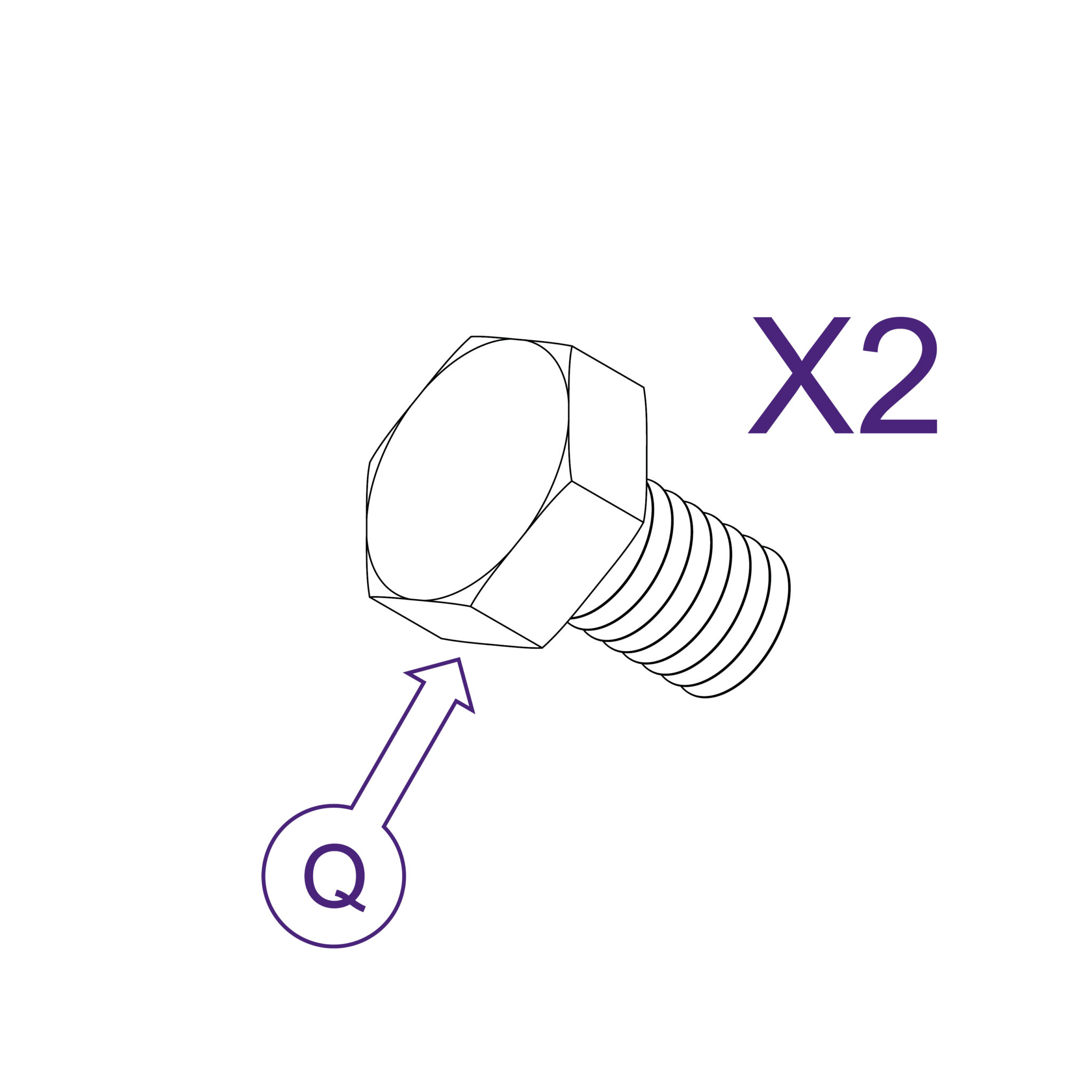
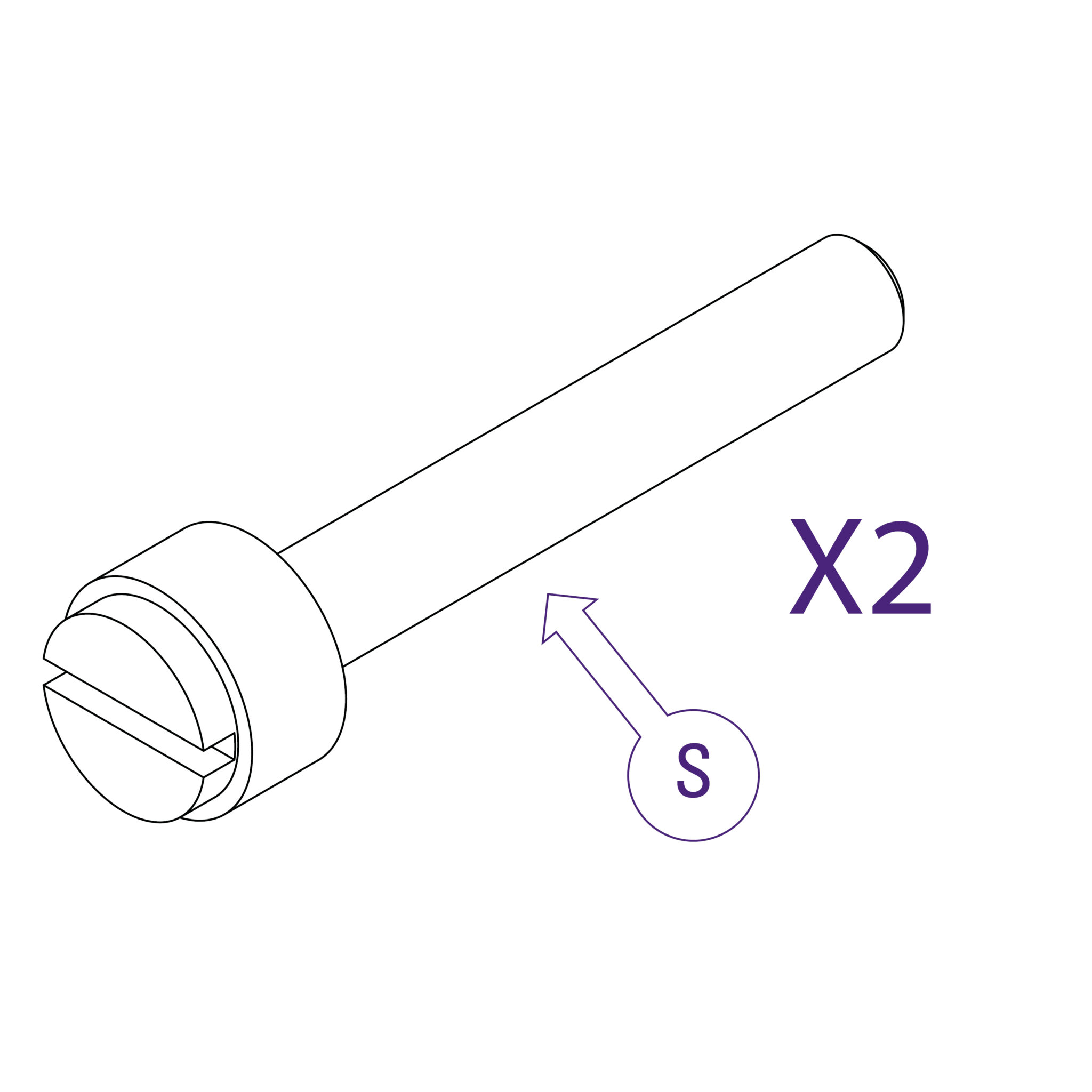
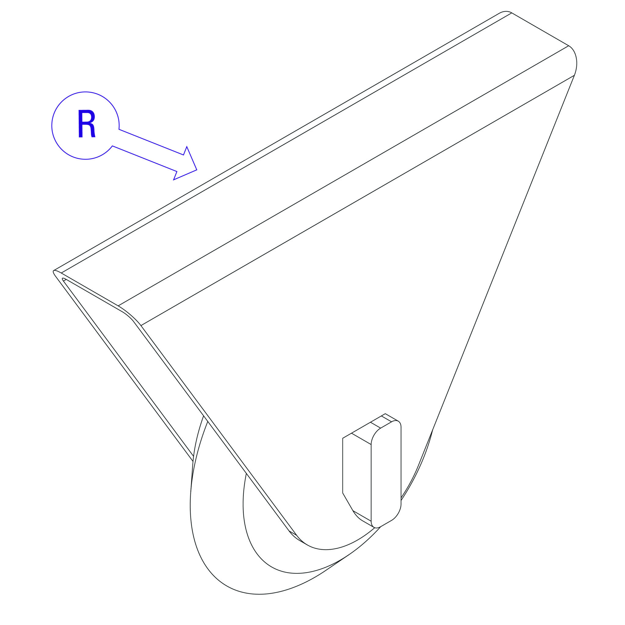
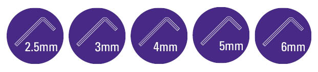
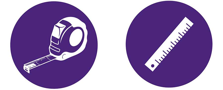


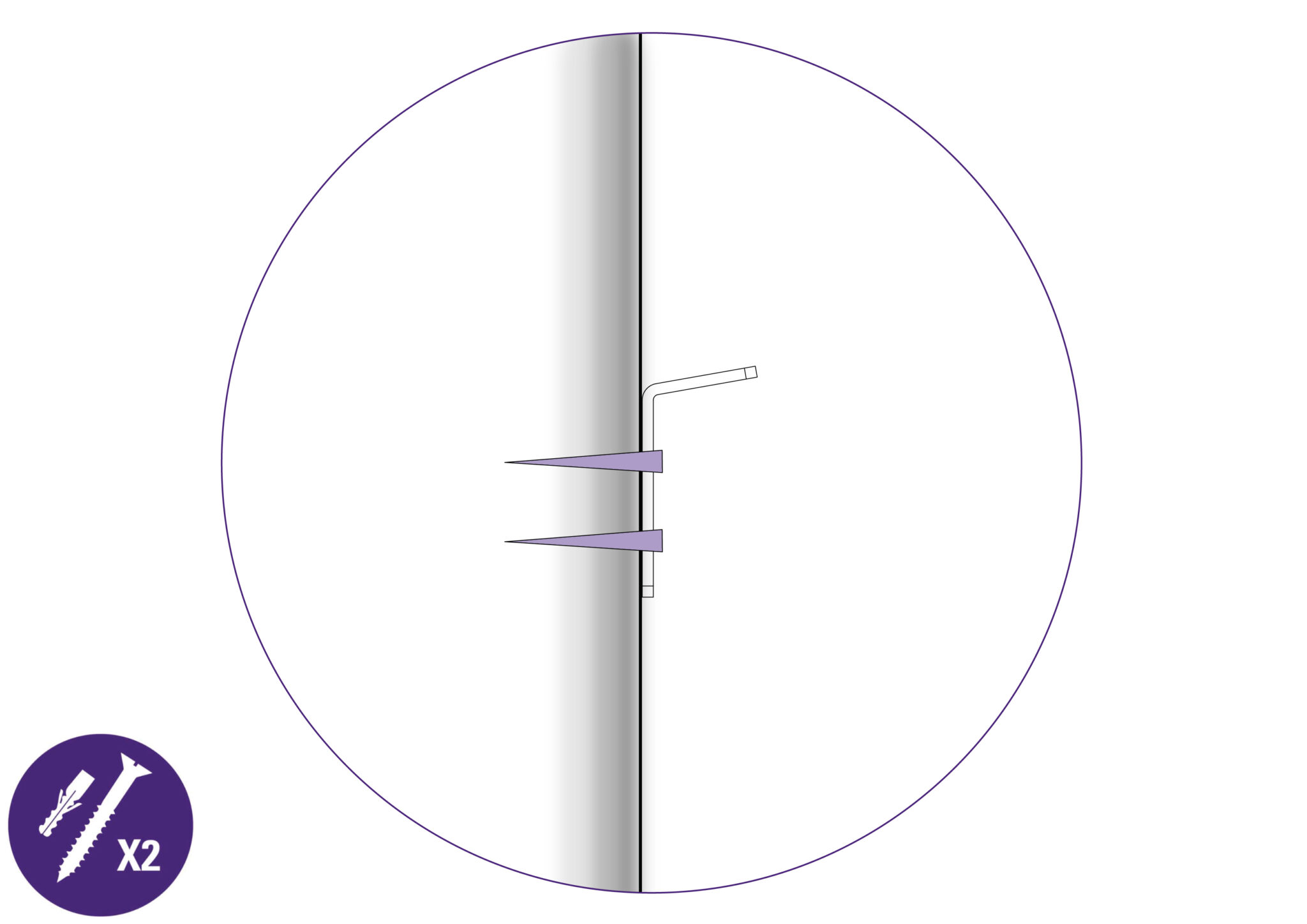
If the installer expects to fix the machine to a wall instead of the Free-Standing Kit, suitable fixings will be required depending on the wall construction. Rawl plugs (as shown above) may accordingly not be a necessity.

The first stages of assembly are carried out with the machine laying on the floor.
NOTE: When lifting the main body from the box DO NOT lift using the black handles on the cutters.
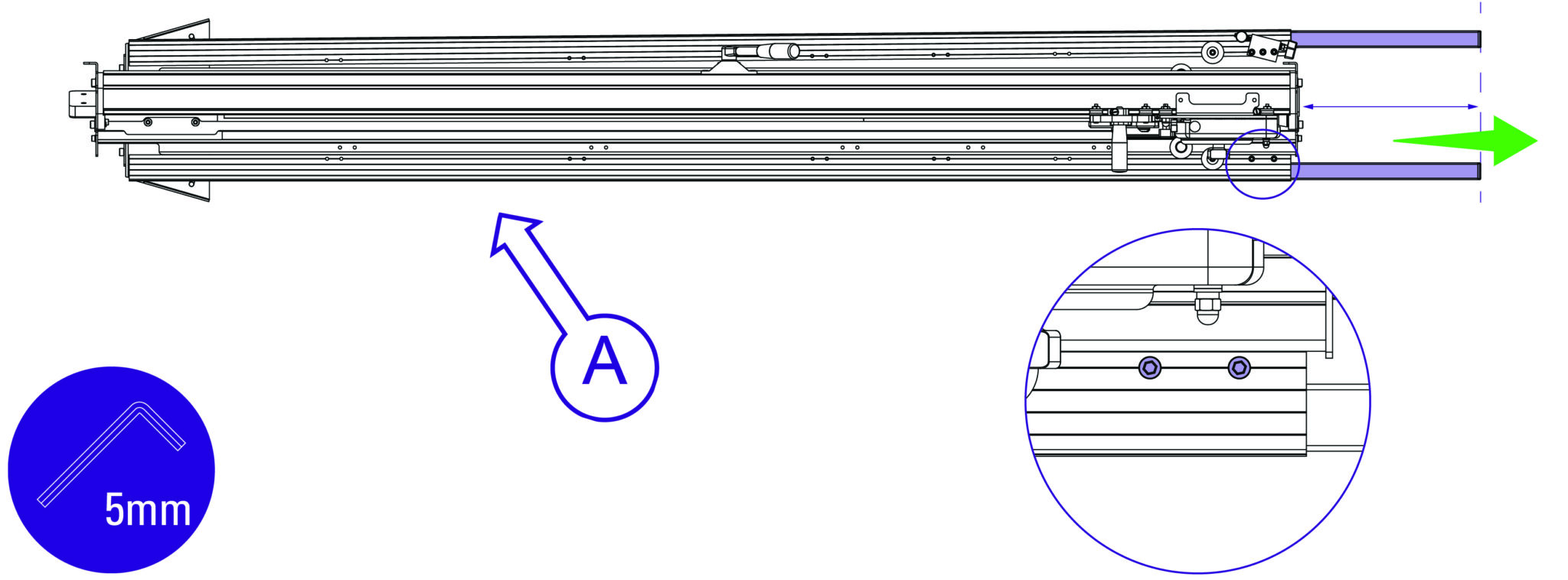
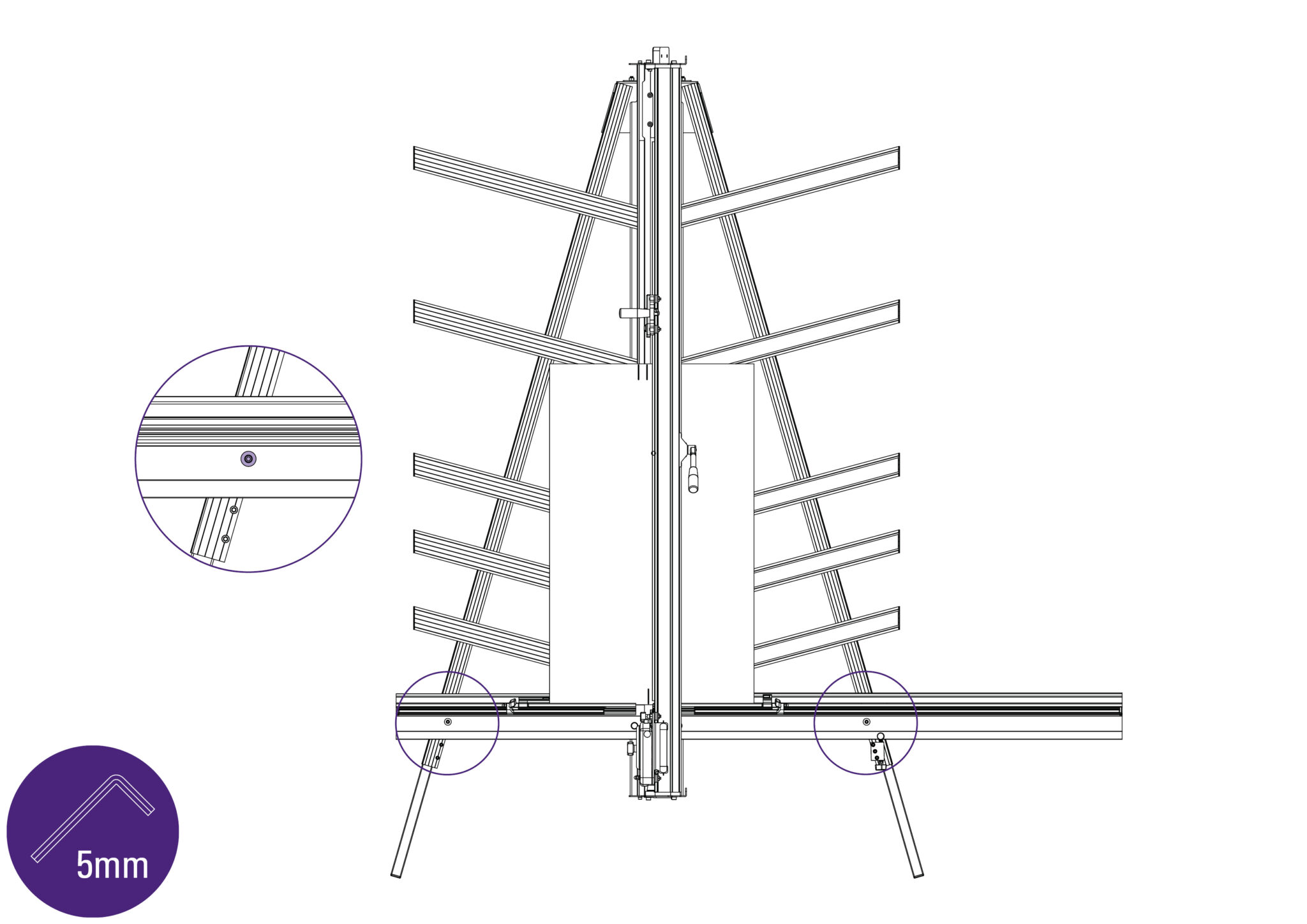
NOTE: These can be re-adjusted later before fixing the machine to the wall
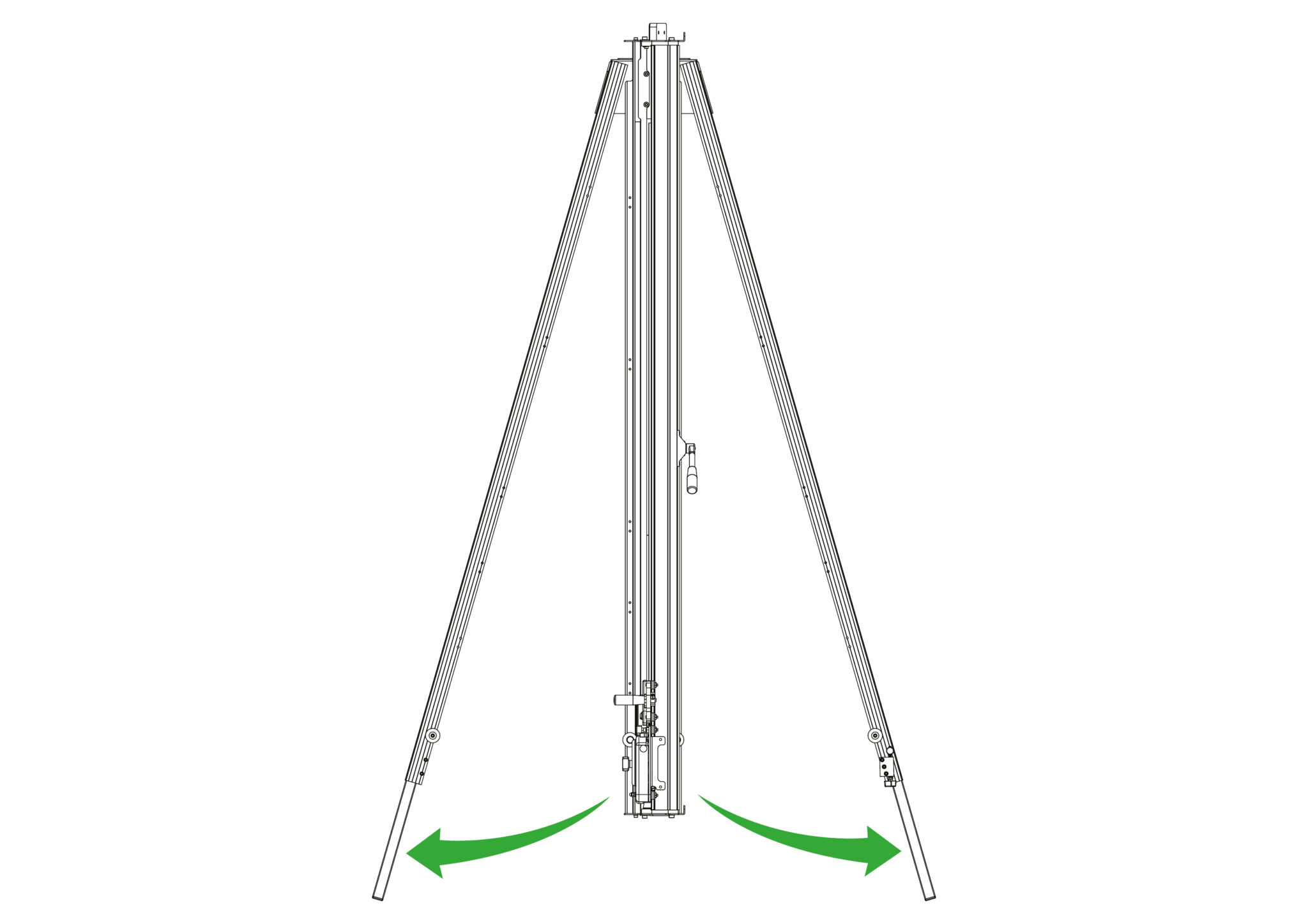
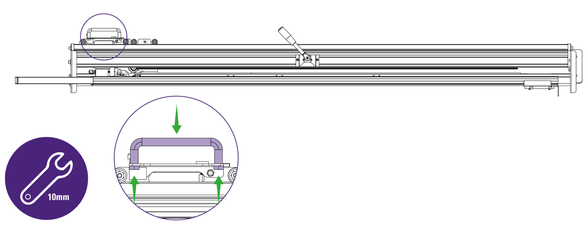
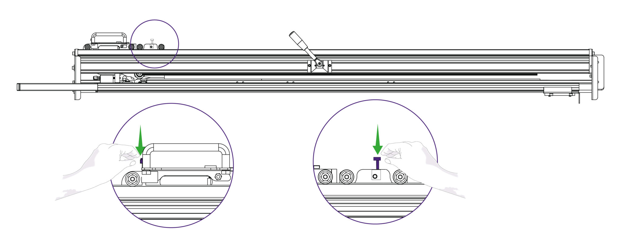
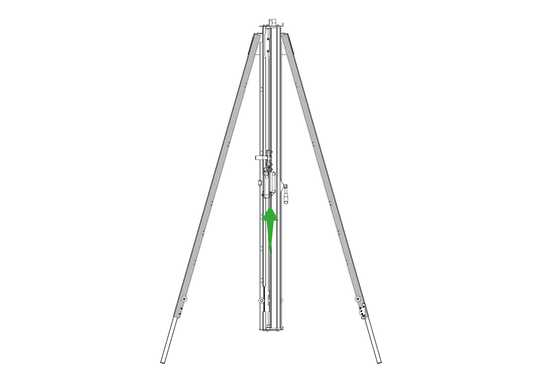
Take care in handling the slack wire when moving the heads from the bottom of the machine, whilst the machine is laying flat.
NOTE: Take note how the following items are fixed in place, as they will need to be replaced after the Squaring Arm has been fitted.
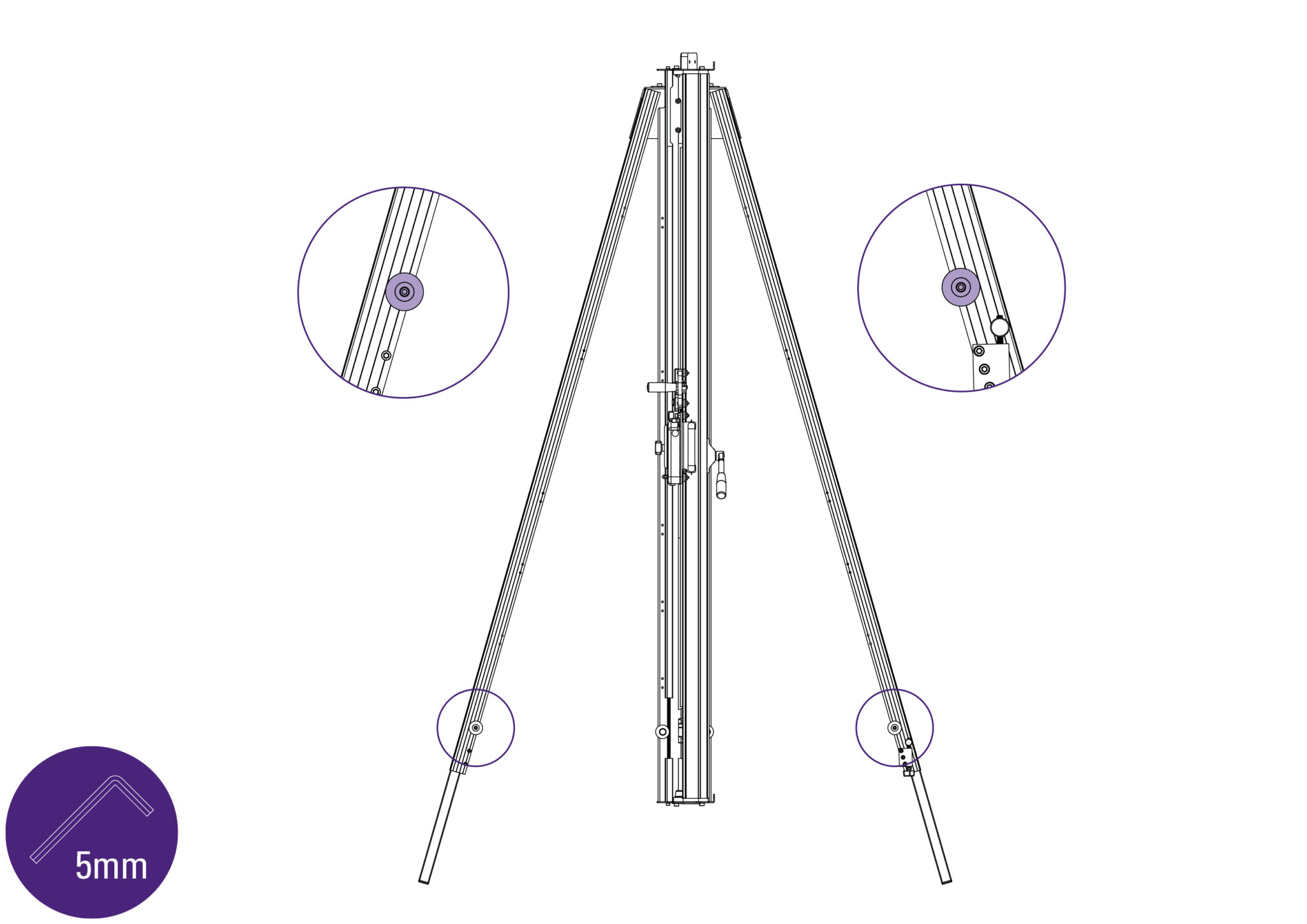
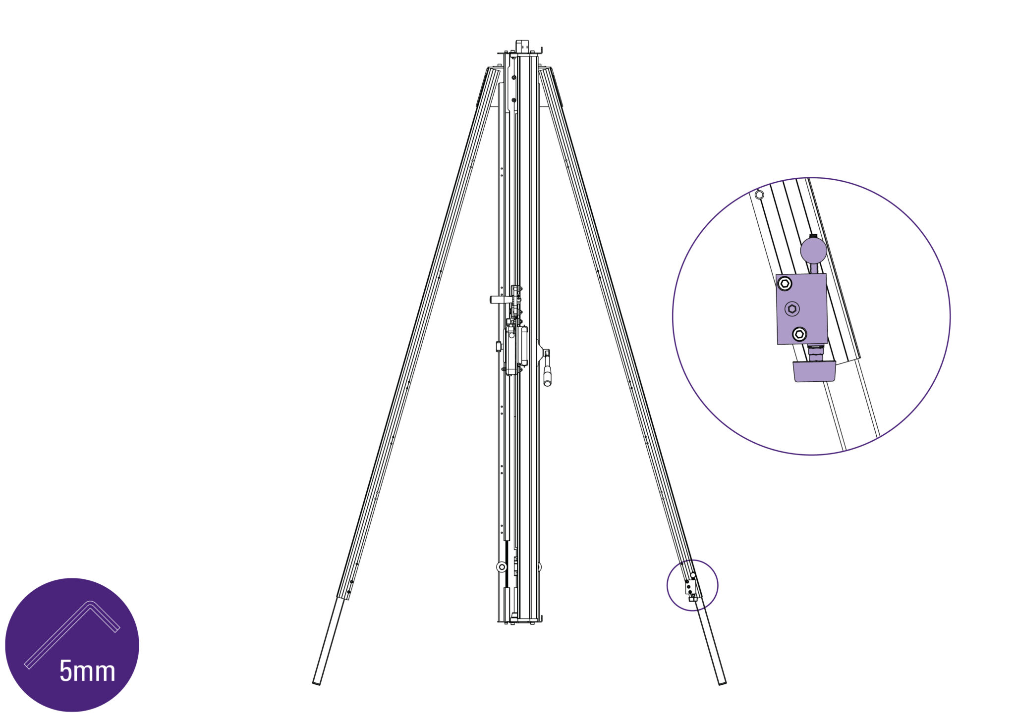
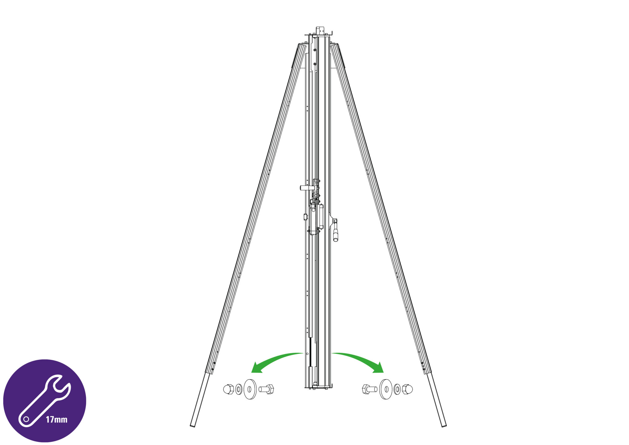
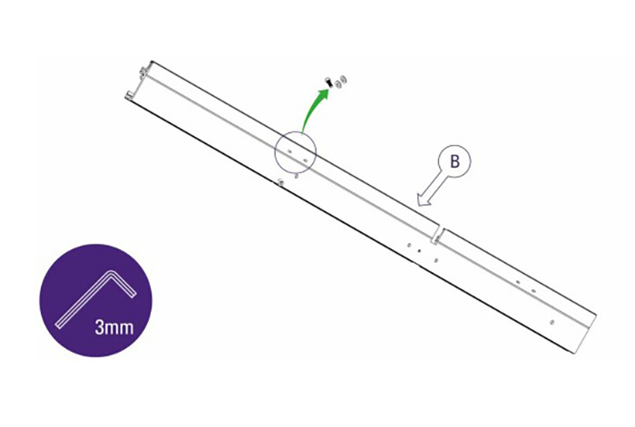
NOTE: Be cautious of sharp edges when installing the squaring arm.
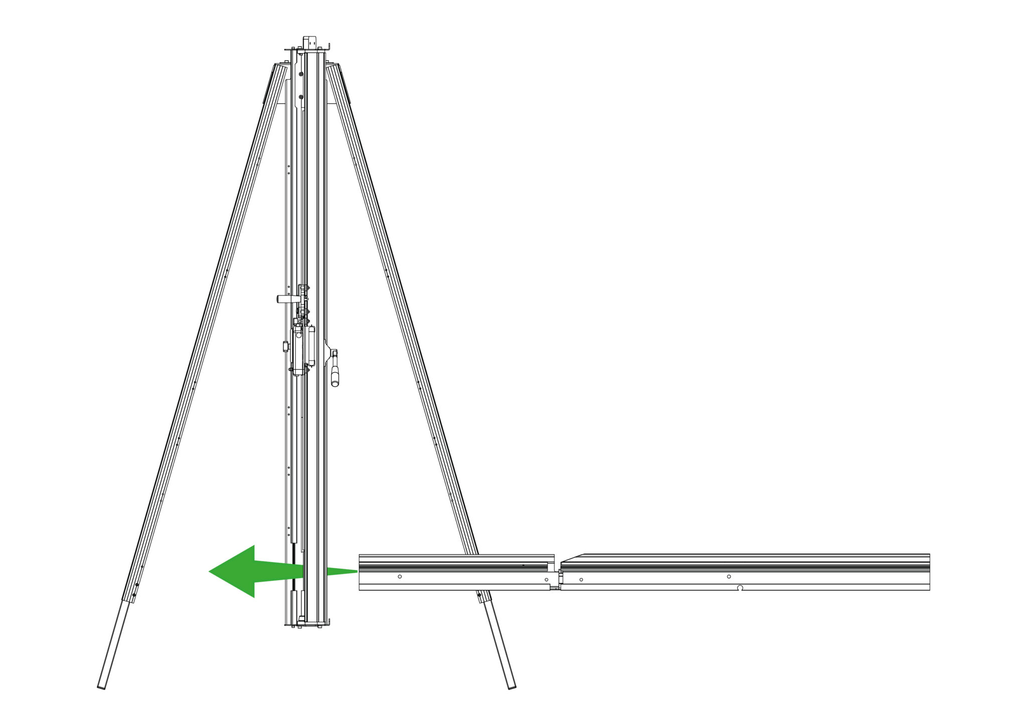
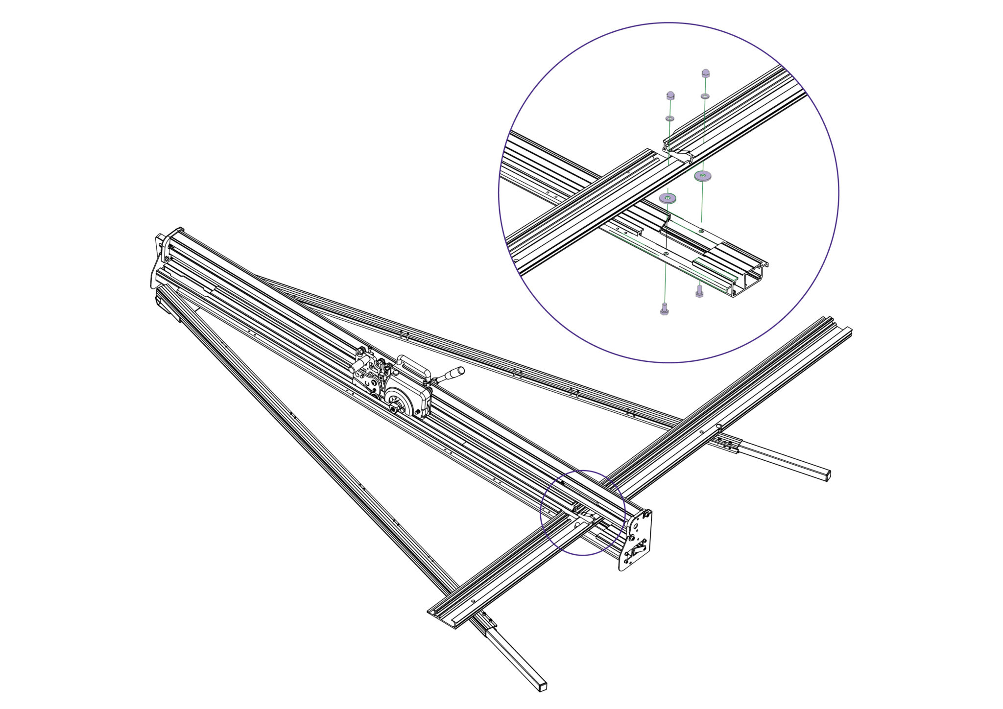
NOTE: Ensure spacer is placed correctly in between the main body and squaring arm, to prevent issues with material cuts.
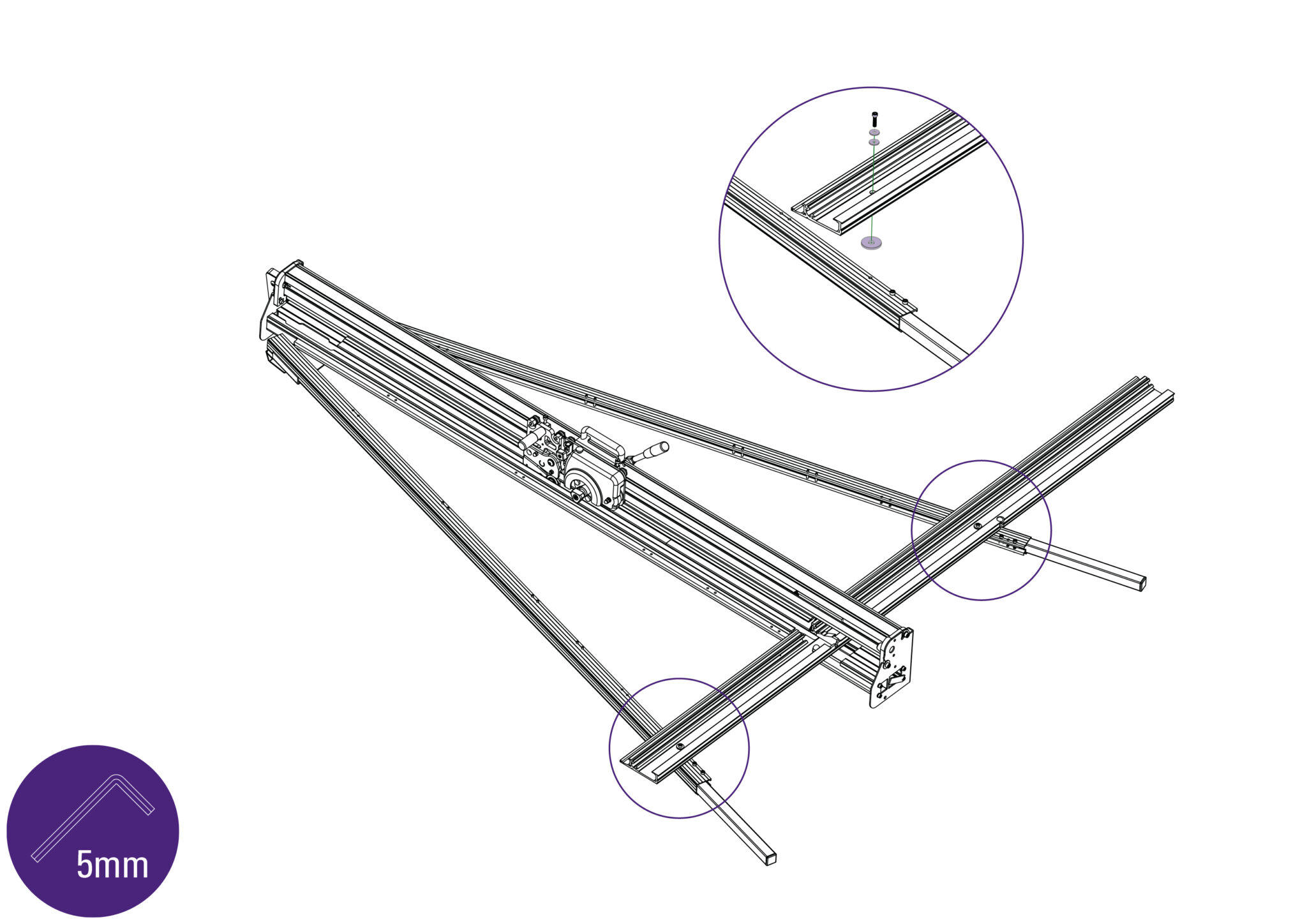
NOTE: Ensure spacer is placed appropriately in between each leg and the squaring arm, to prevent issues with material cuts.
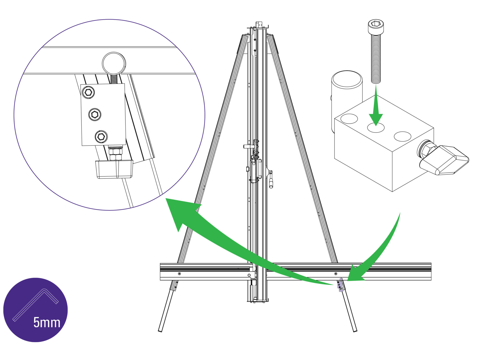
Refit the squaring adjuster block by firstly sliding the steel bar into the opening in the Squaring Arm, then align the heads of the two screws in the leg to fit the top and bottom holes in the adjuster block.
The screws fixing the Squaring Arm to the machine should still be loose and allow it some movement to help alignment.
Insert and tighten the screw in the middle hole.
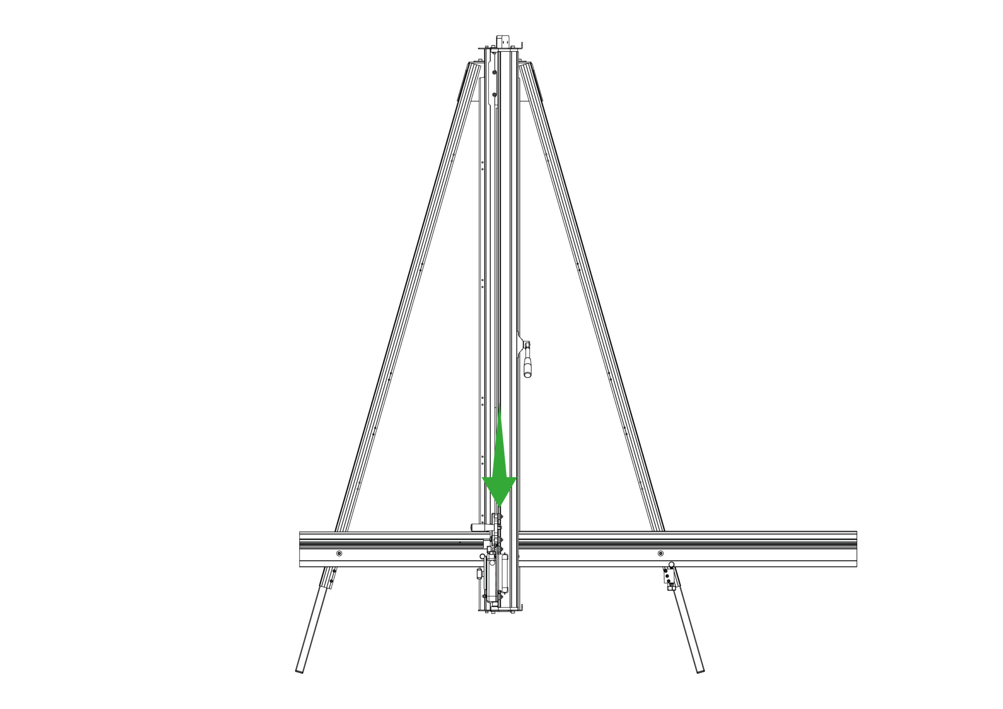
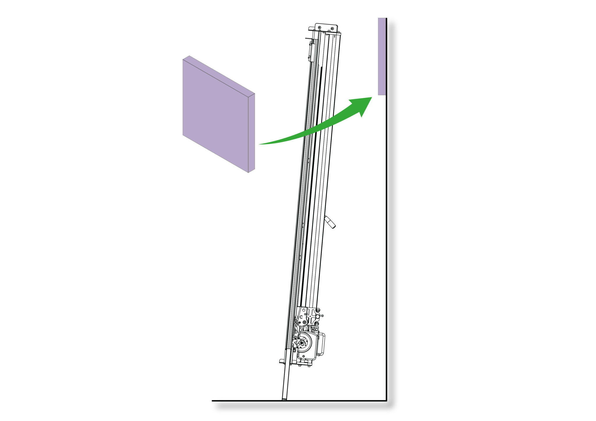
Get help to slowly lift the machine and lean it so that the front faces towards the wall. If the machine is too high or too low, bring the machine back down and refer back to Adjusting the legs> to adjust the machine height.
If the height is satisfactory, carefully place a scrap of card or board in between the top end of the machine and the wall to prevent any damage.
 |
Be careful when lifting |
NOTE: Ensure the machine is tied or held in position safely whilst the following steps are carried out.
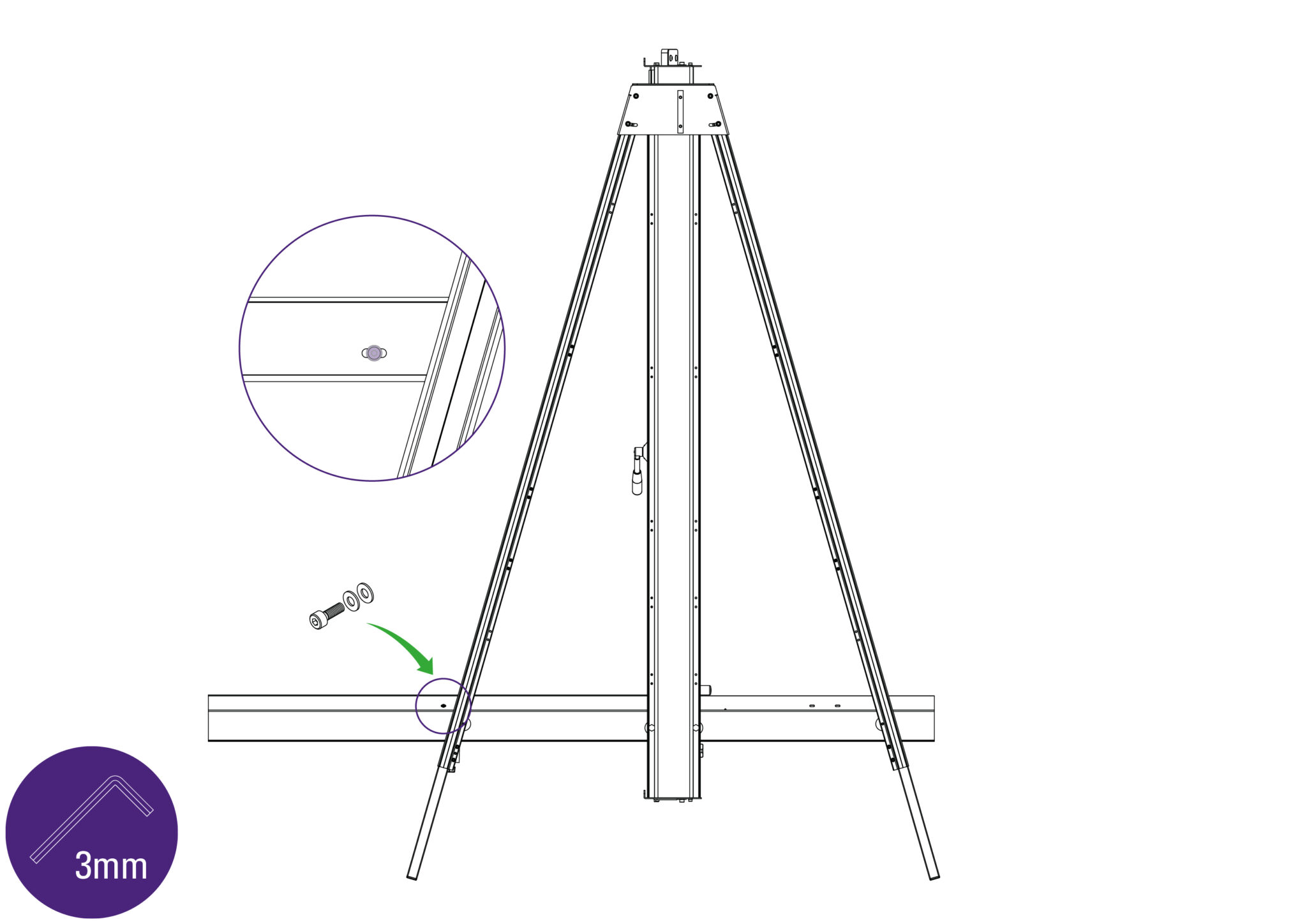
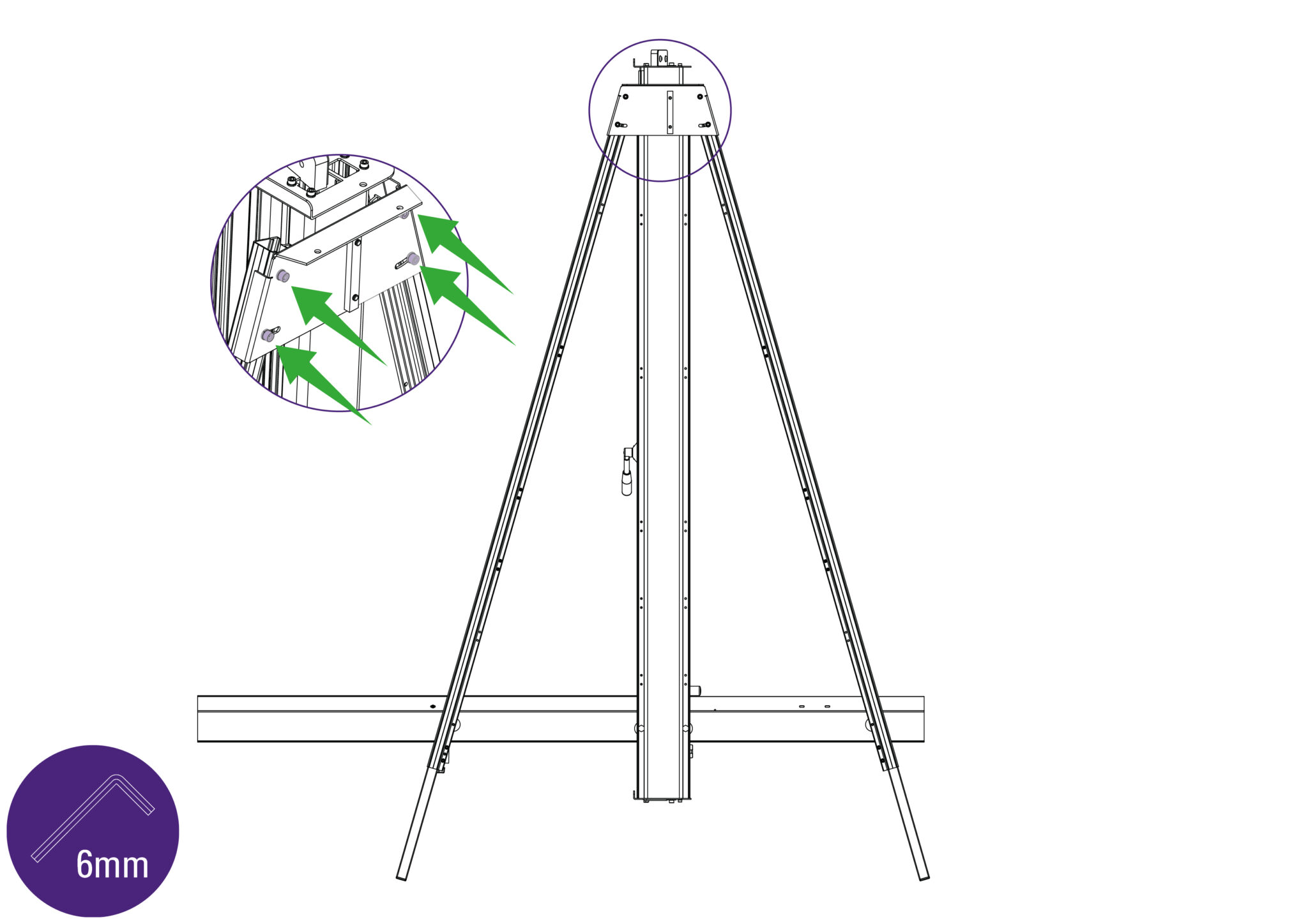
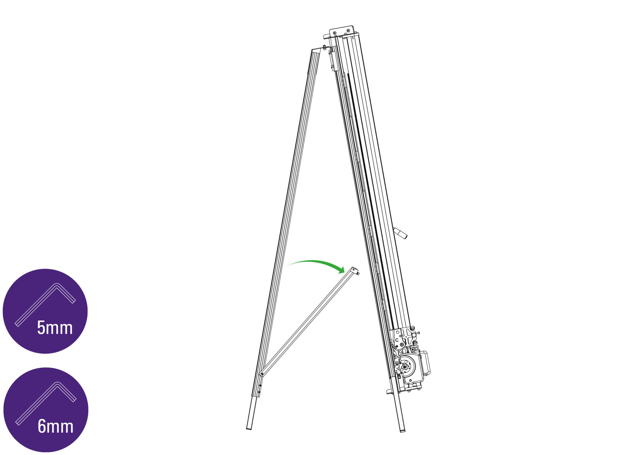
NOTE: The screws fit into special grooves in the underside of the supports. The grooves have teeth on their sides to match the teeth of the screw thread, the screw can be fitted in the groove anywhere along its length but be careful to make sure the screw is kept perpendicular to the support and not screwed in out of line.
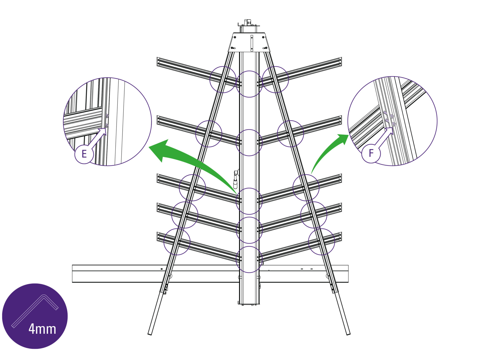
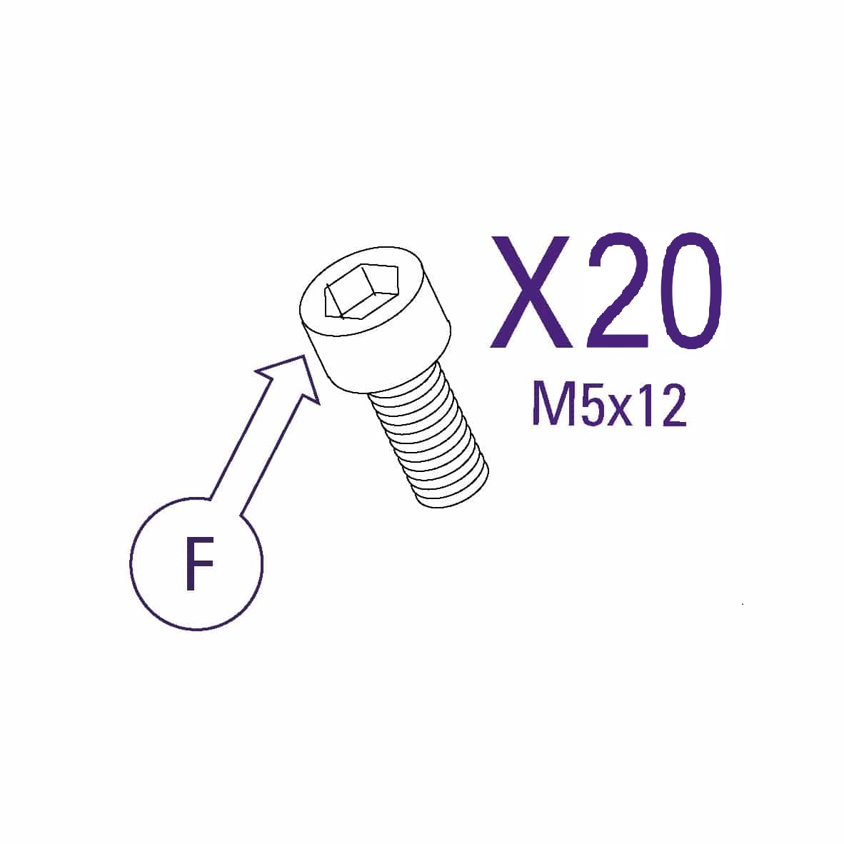
Use one of the short screws (part F) to fix the support arm to the main body, and one of the long screws (part E) in each of the holes along the legs of the machine. Ensure the ends of the supports are firmly against the Main Body and the screws are aligned with the special grooves as explained above.
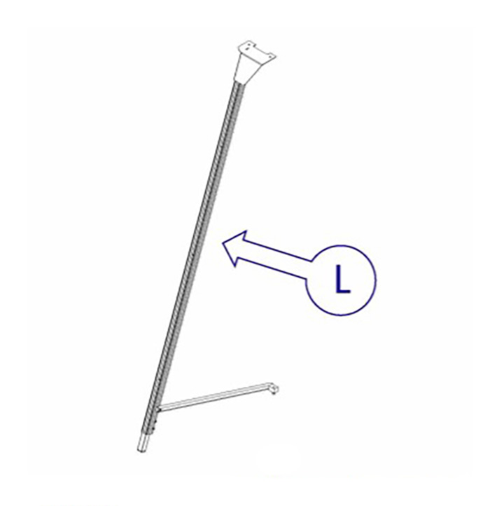
If a free standing kit is to be fitted to the machine, proceed directly to Fitting the optional free standing kit >
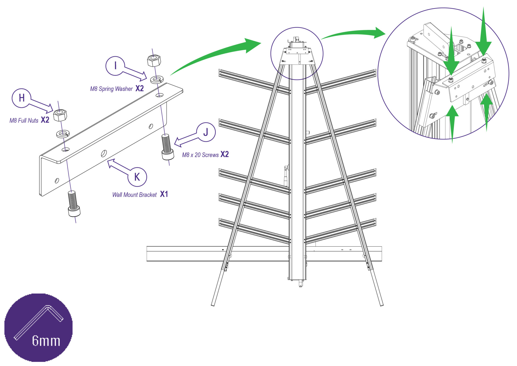
NOTE: If a free standing kit is to be fitted to the machine, proceed directly to Fitting the optional free standing kit >
NOTE: Ensure the wall is stable and use the appropriate fixings.
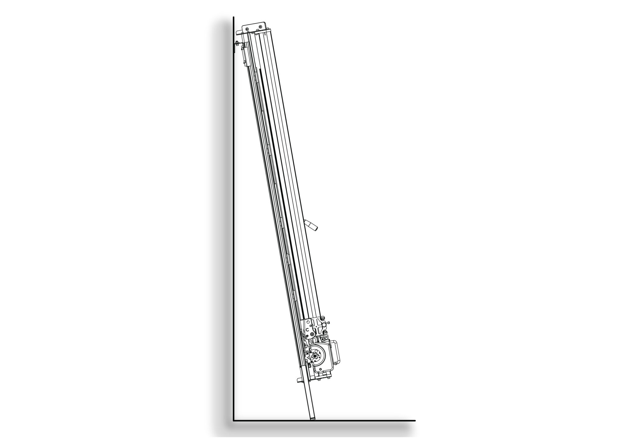
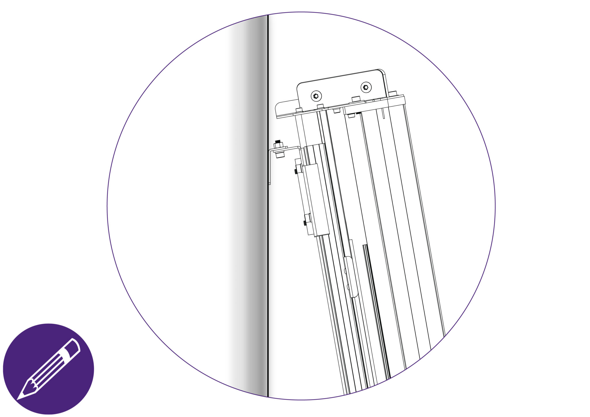
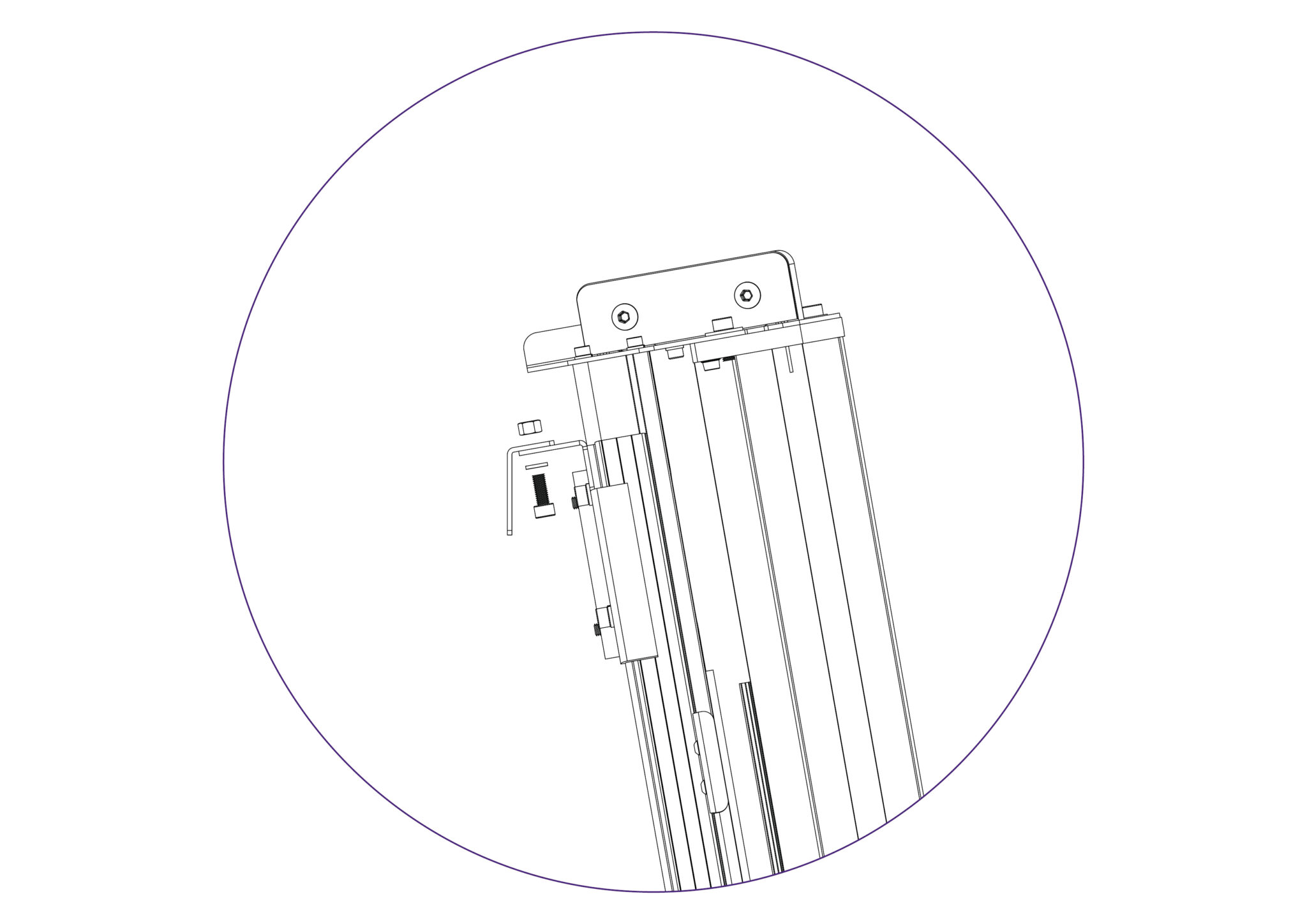
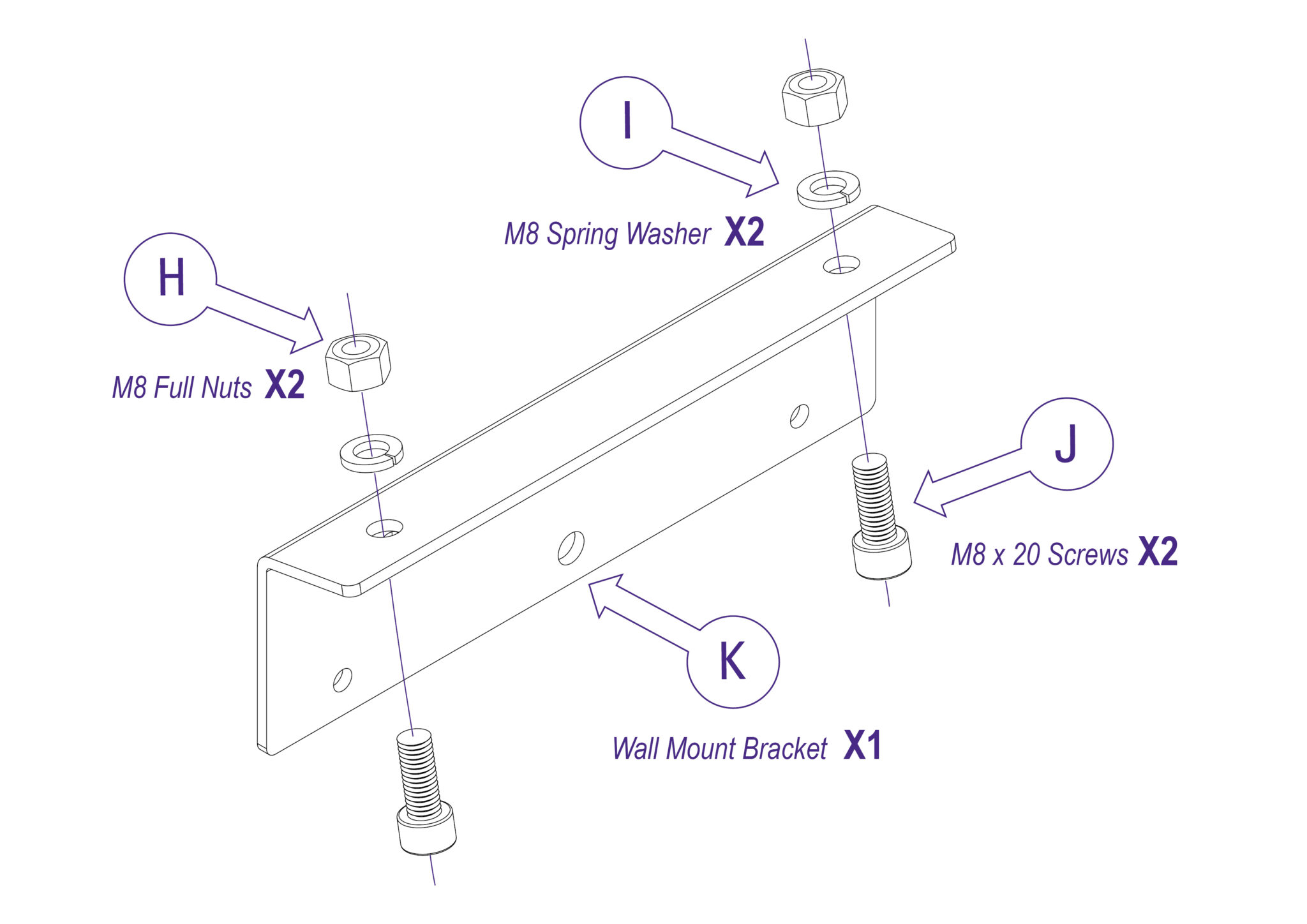
Attach the Bracket to the wall in the marked position with appropriate fixings then reposition and fasten the machine to the bracket.
Proceed to Checking the machine for squareness >
NOTE: The free standing kit is an optional extra and does not come packed with the main machine.
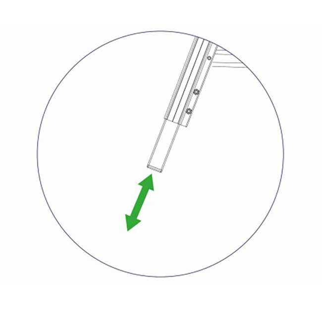
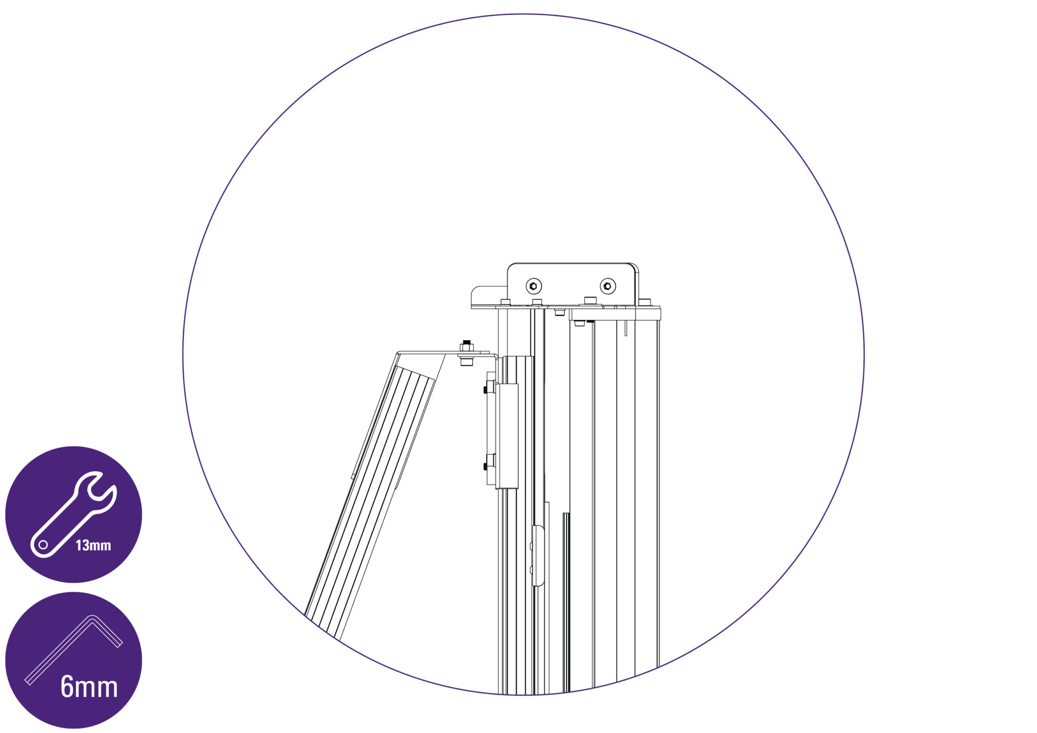
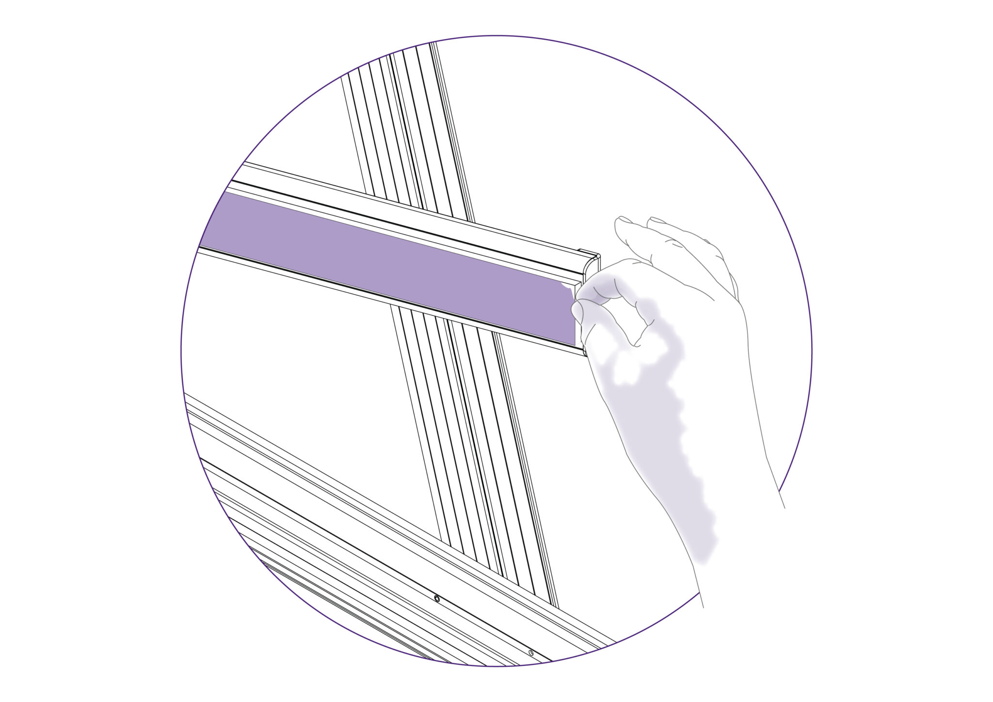
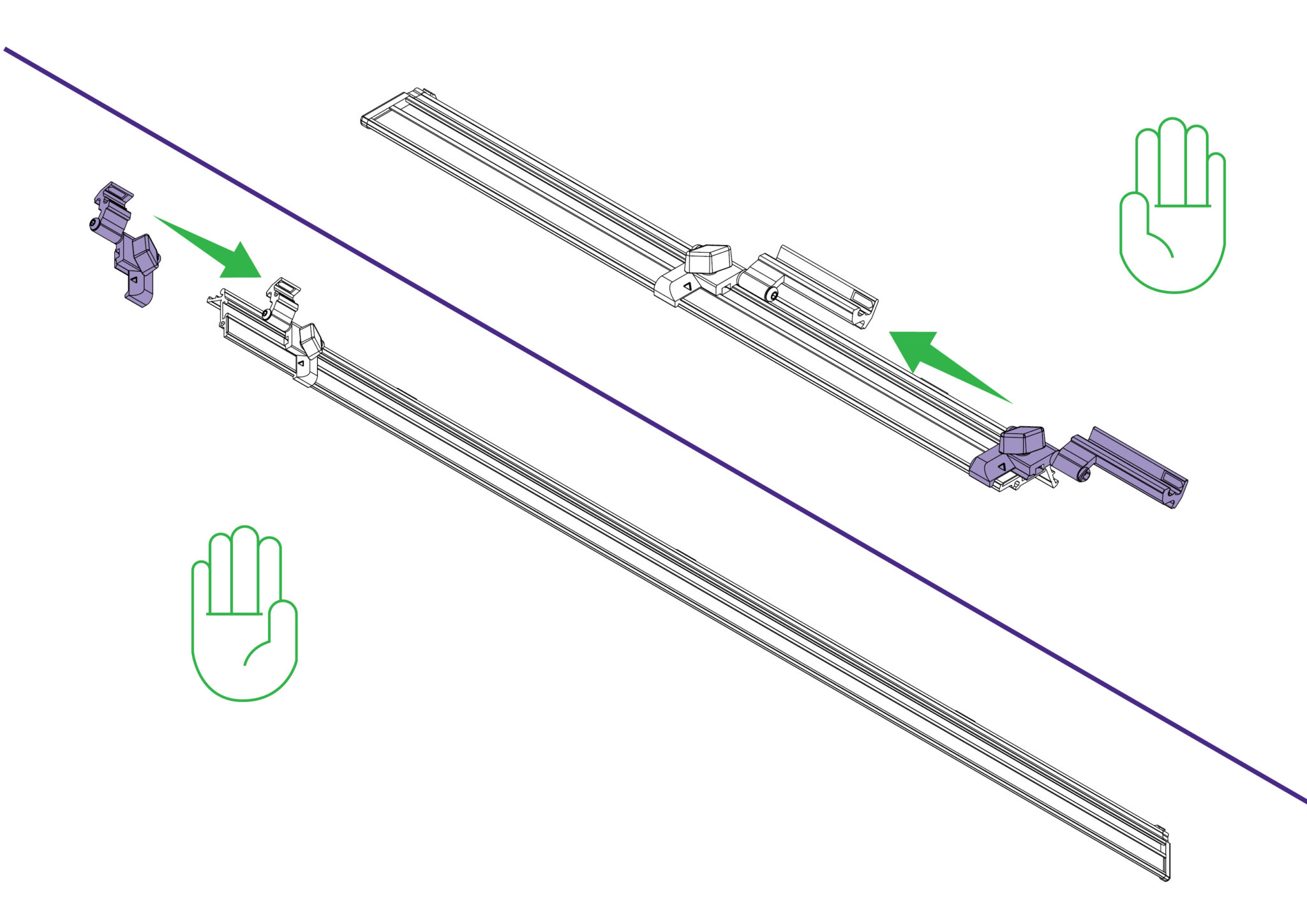
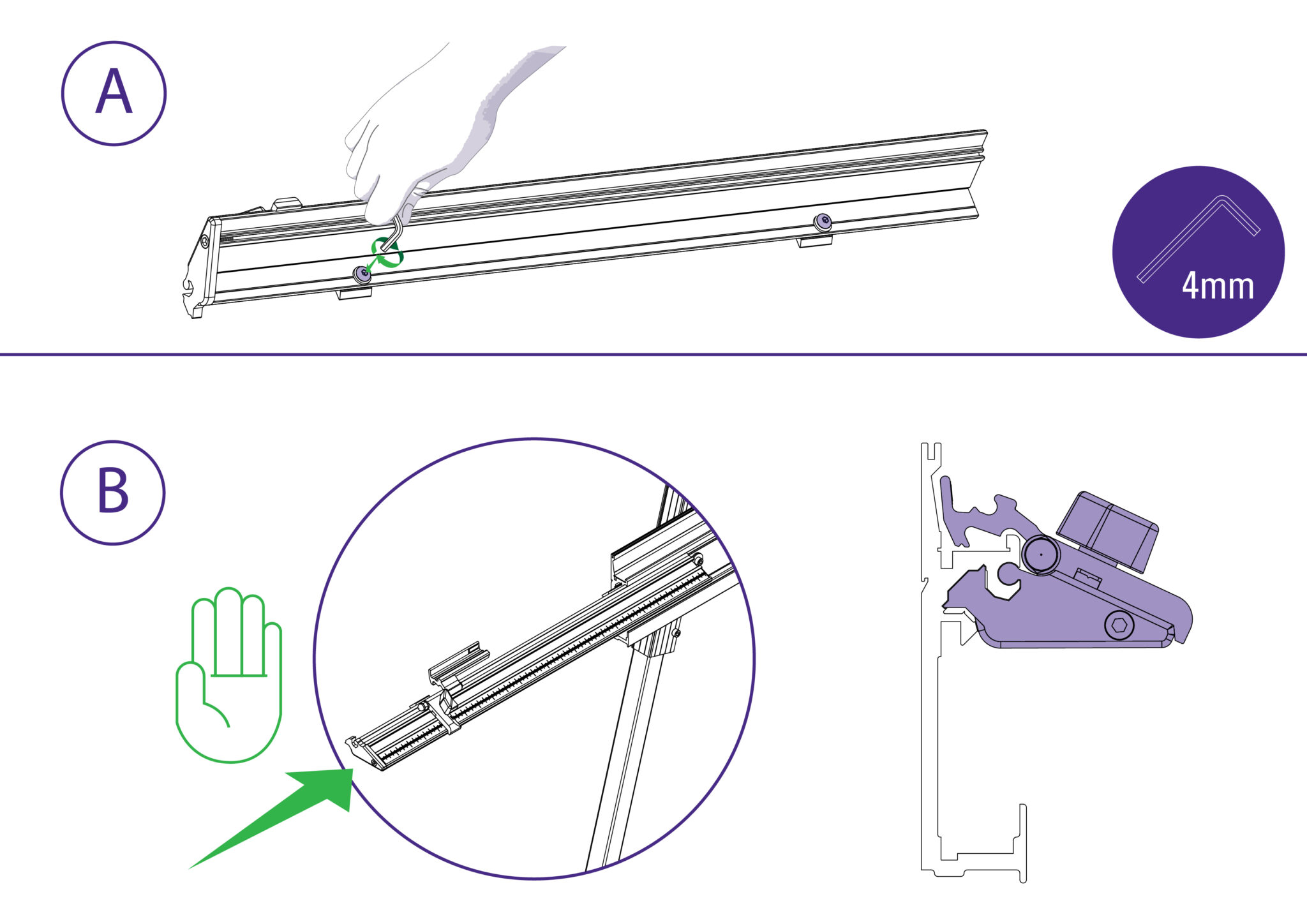
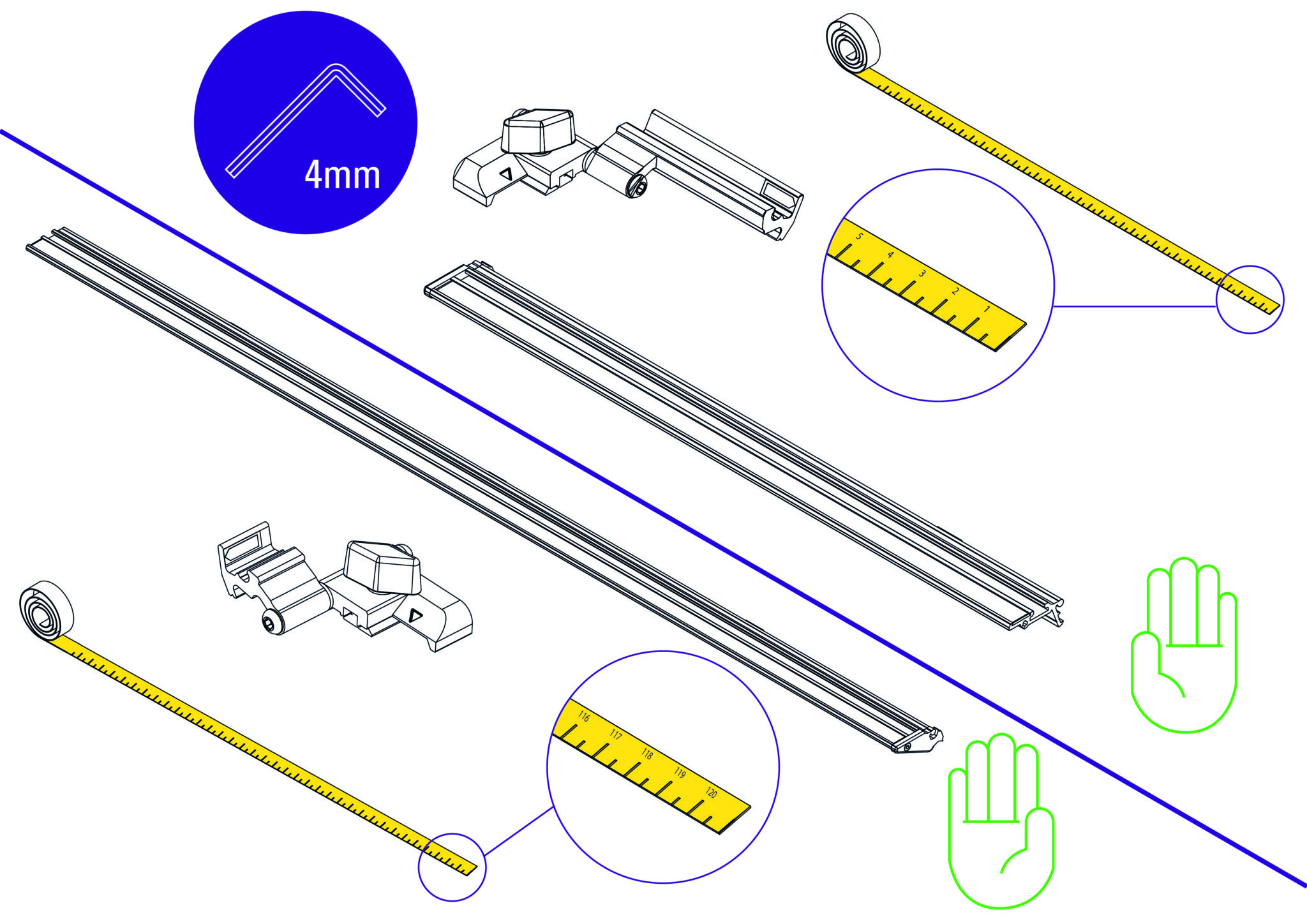
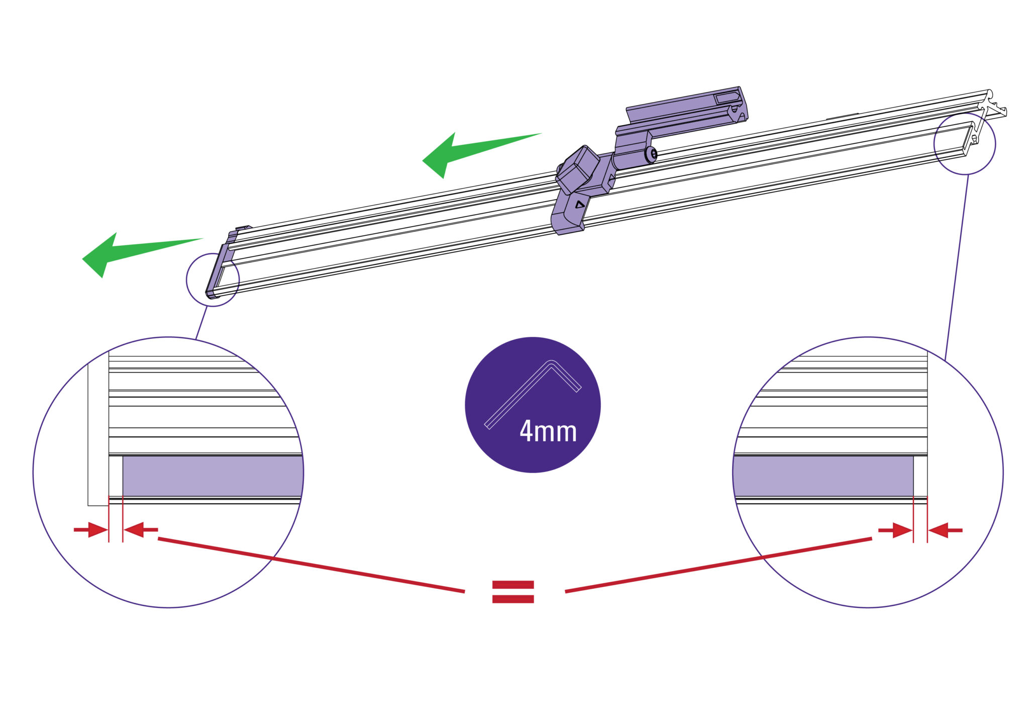
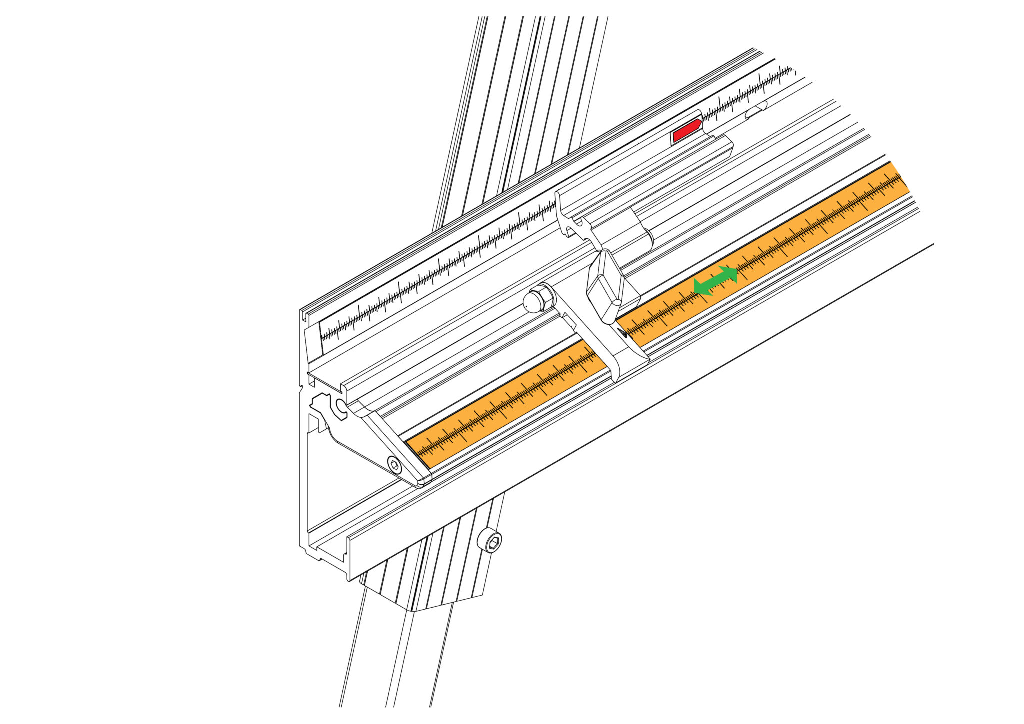
A) Loosen the two screws so the fixing blocks allow the Easy Measuring Scale to slide onto the squaring arm.
B) Ensure the end cap is flush with end of the squaring arm and tighten the two fixing screws using a 4mm Allen (Hex) key.
 |
Do this firmly |
  |
Left hand side |
Repeat the process on the right hand side.
NOTE: Adjust the end cap such that it fits into the squaring arm groove, if necessary.
NOTE: For your machine to produce accurate square cuts the main body needs to be set so that it is 90° to the squaring arm. For the following squaring procedure you will need a piece of card or easily cut board at least 60cm x 100cm (24" x 39"). The larger the board the more accurate you can set the machine.
Note: It would be useful to cover the “Get to know your cutter”> sections in the User Manual before proceeding with the following steps.
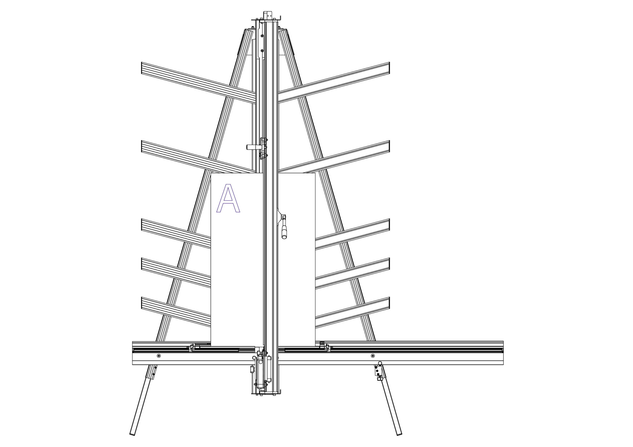
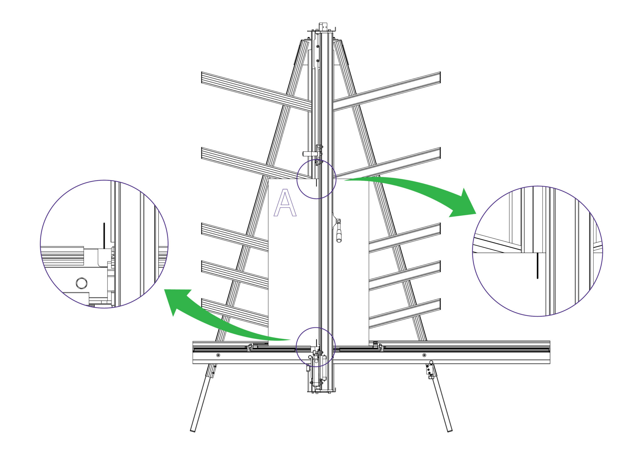
Select the cutting blade on the Multi-Tool Cutting Head.
Cut into the top board to produce a cut approximately 3cm (1”) long. Disengage the cutter using the cutter release lever.
Lower the cutter and make a similar cut at the bottom of the board by pressing the blade through the board about 3cm (1″) from the bottom edge of the board.
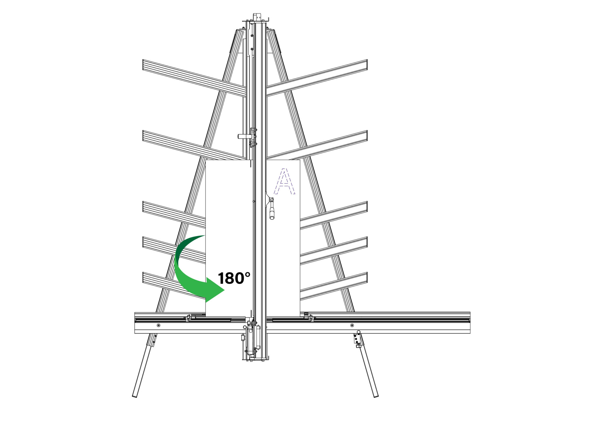
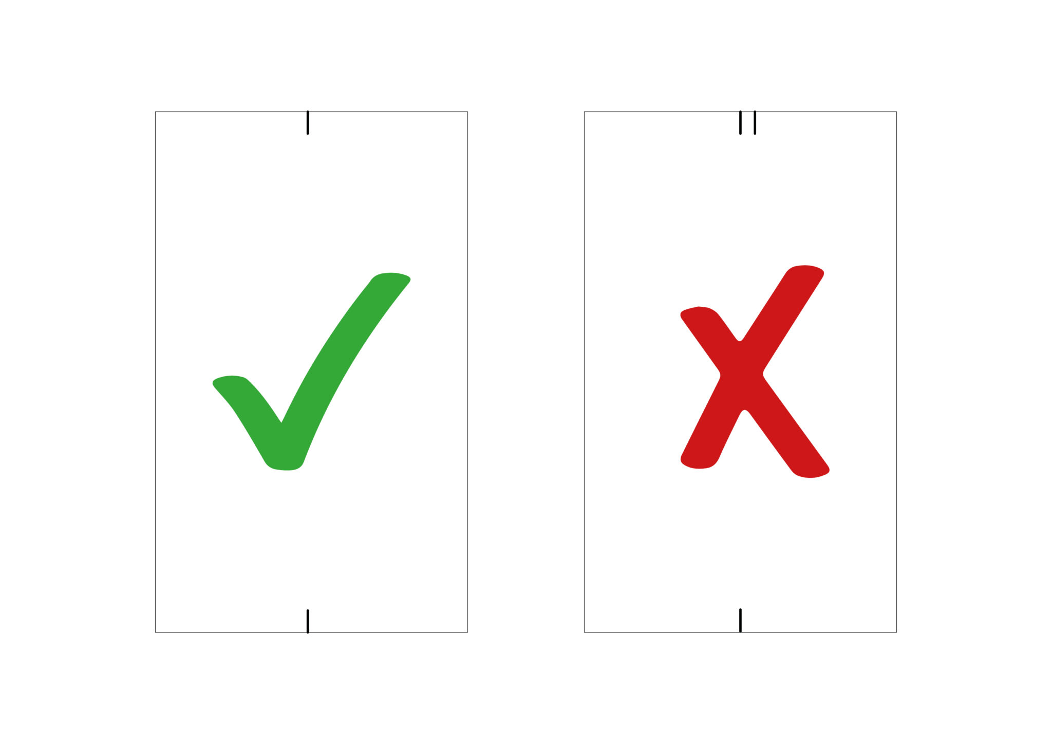
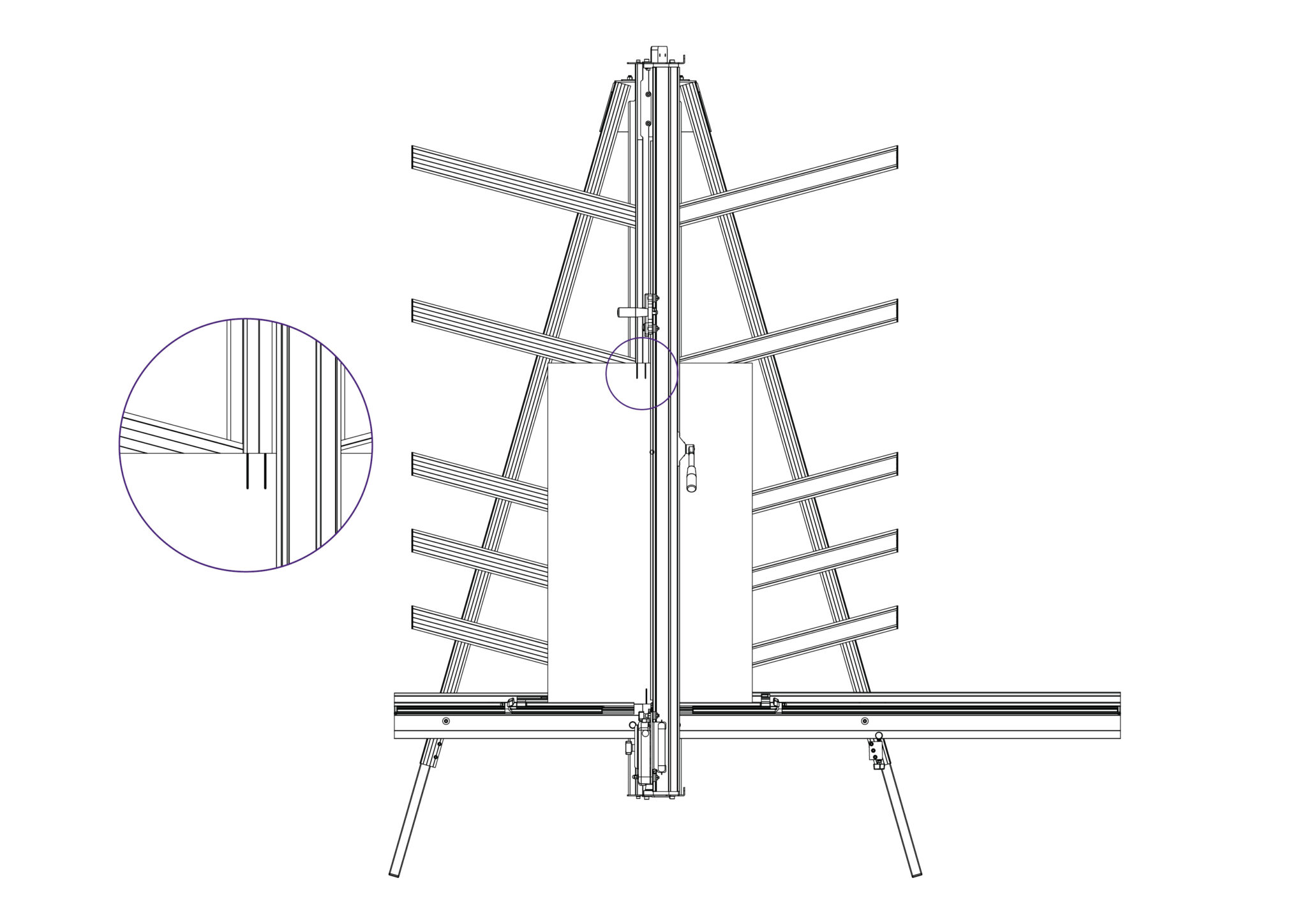
Raise the cutter to the top of the board, and if the machine is square the blade should enter the same cut as made previously. If not refer to Adjusting the squareness> to make the necessary
adjustment.
If it is square, continue to Calibrating the vertical scale>.
NOTE: Before making any adjustments carry out the squareness check as described in Checking the machine for squareness>
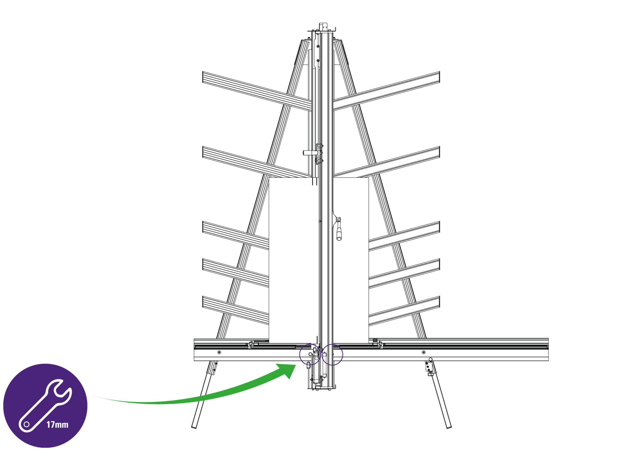
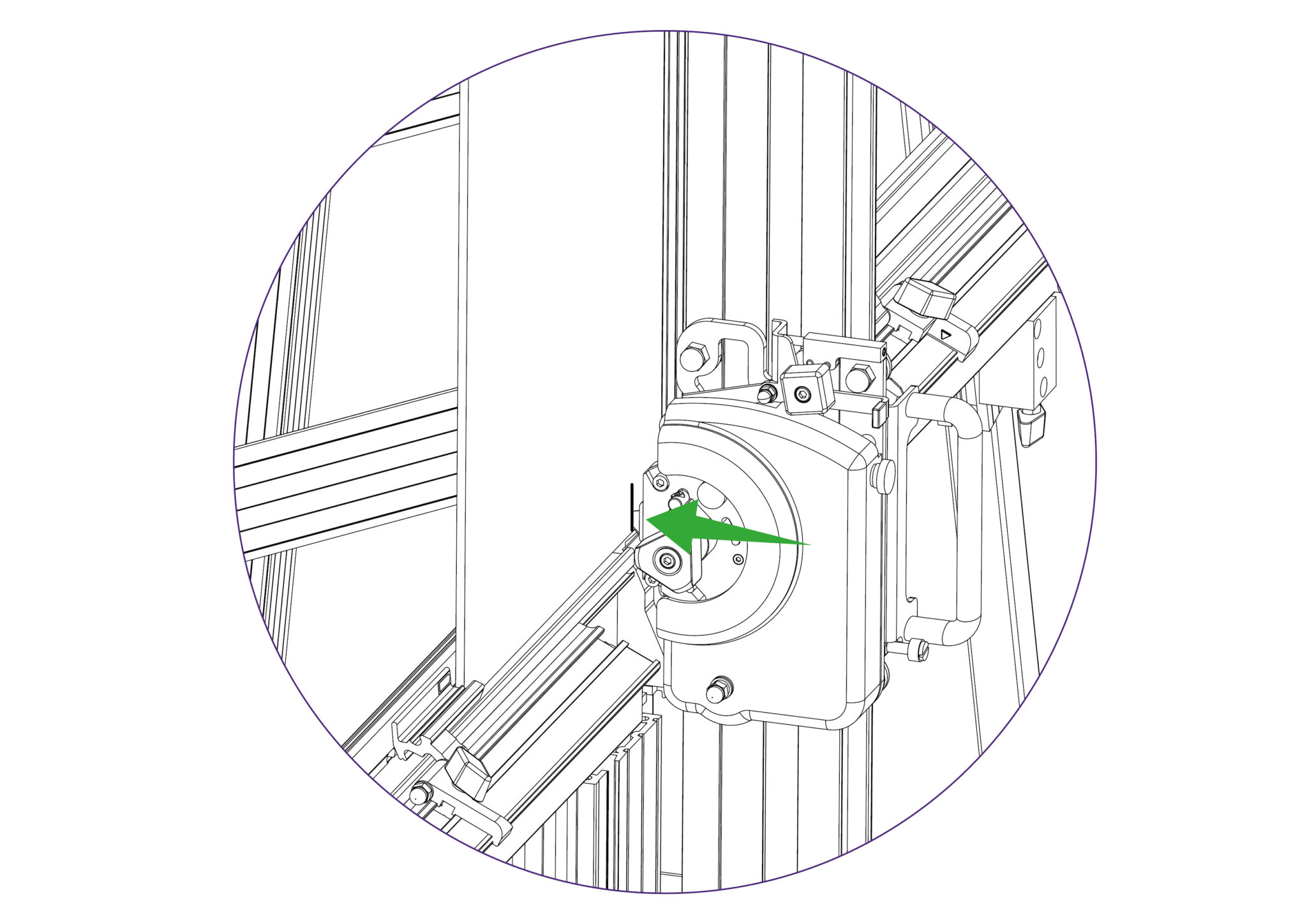
Turn the squaring adjustment knob on the right hand leg in the direction described next, dependent upon the position of the top two cuts.

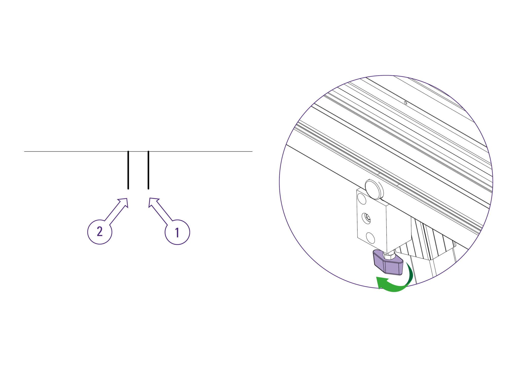
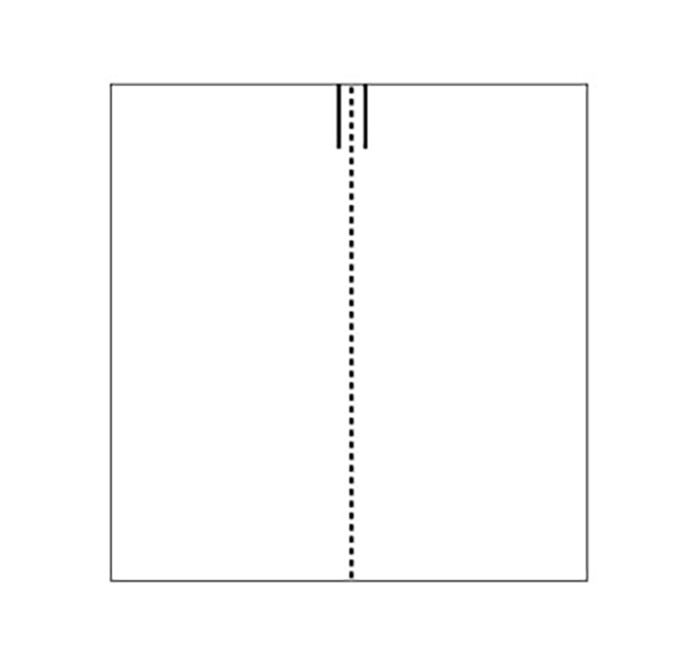
NOTE: Repeat the squareness check and if the cuts align, continue onto the next step. If it does not, repeat the previous steps until it does.
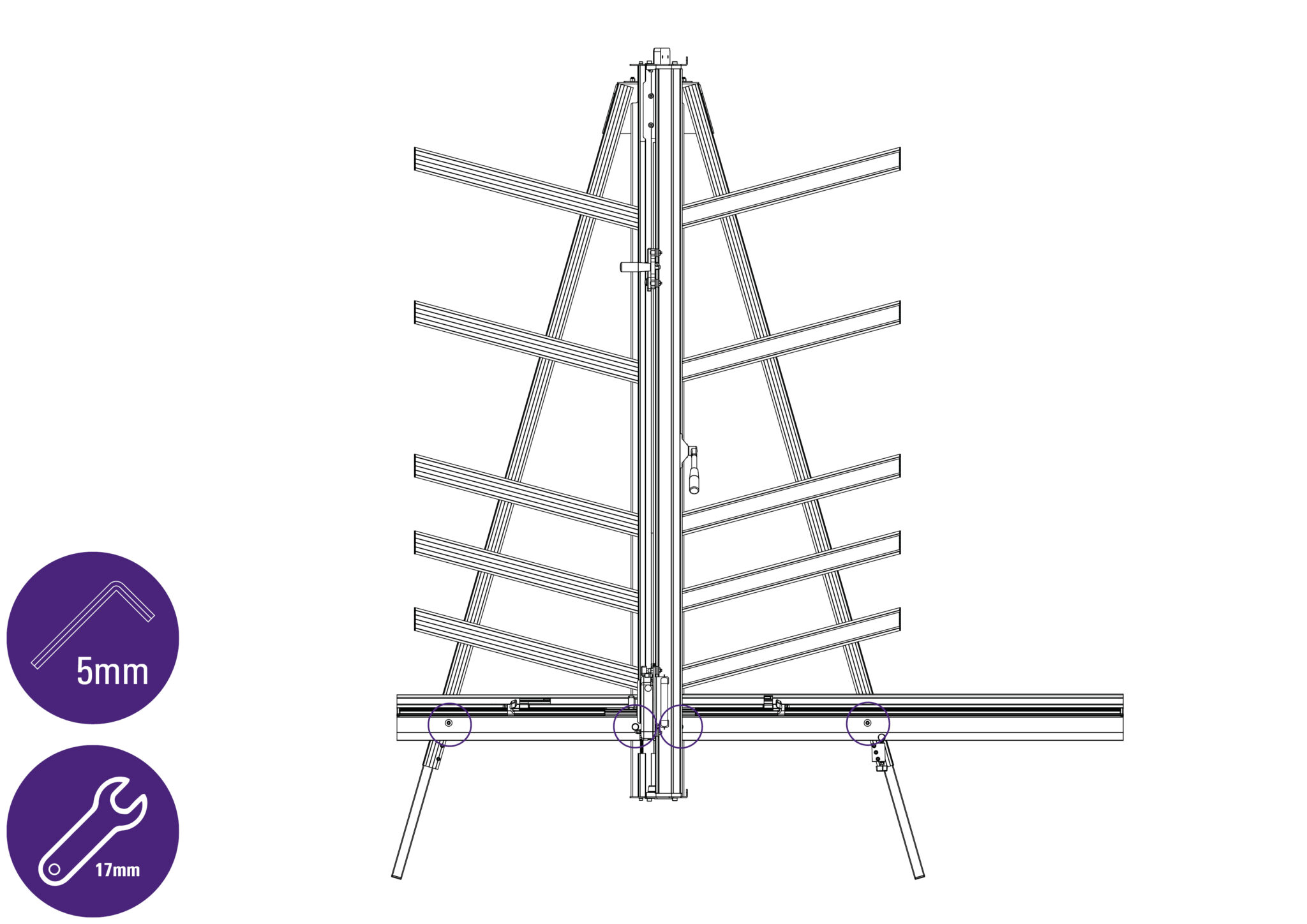
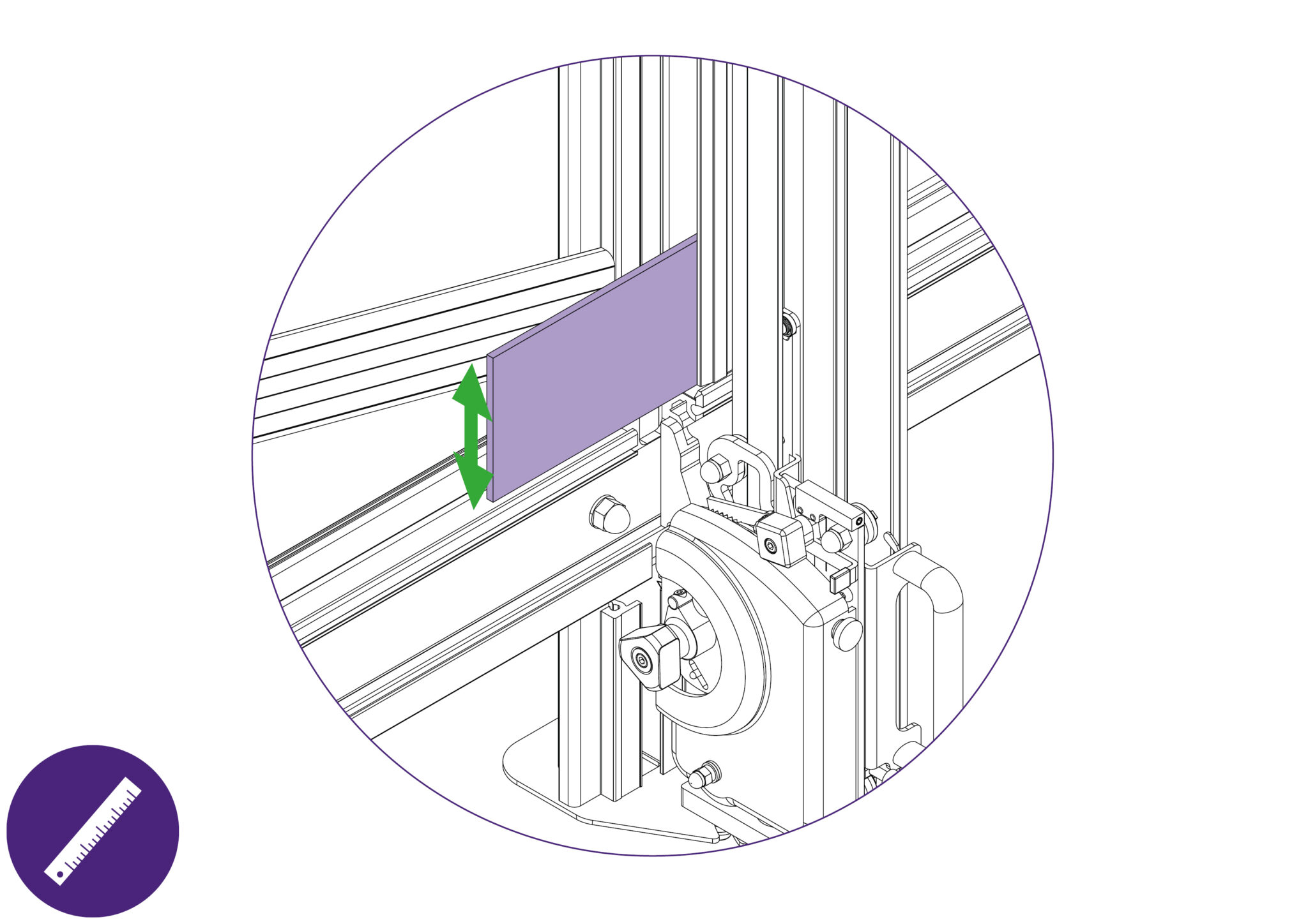
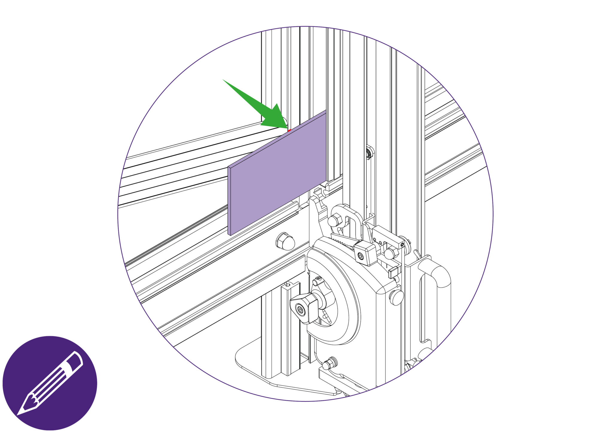
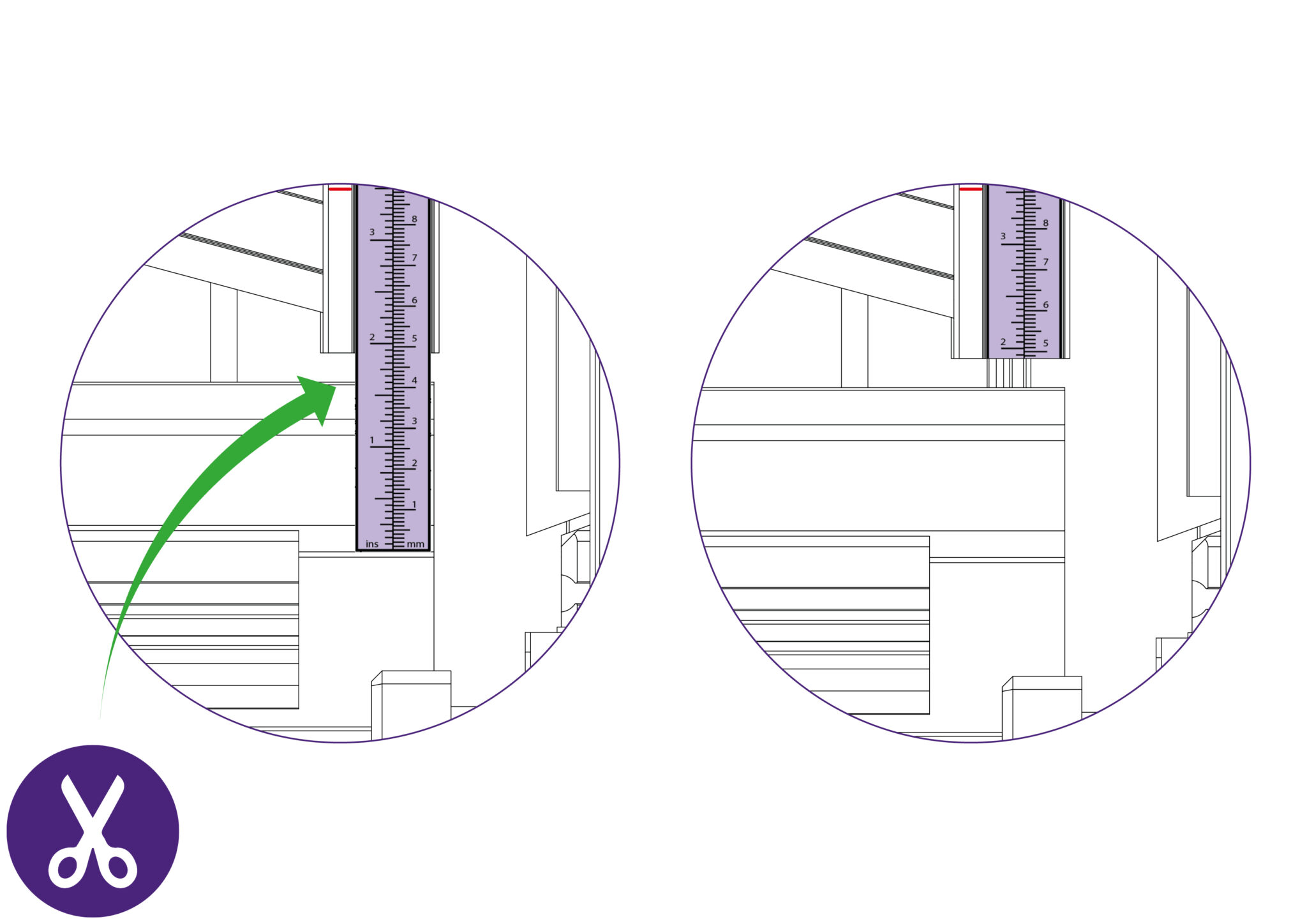
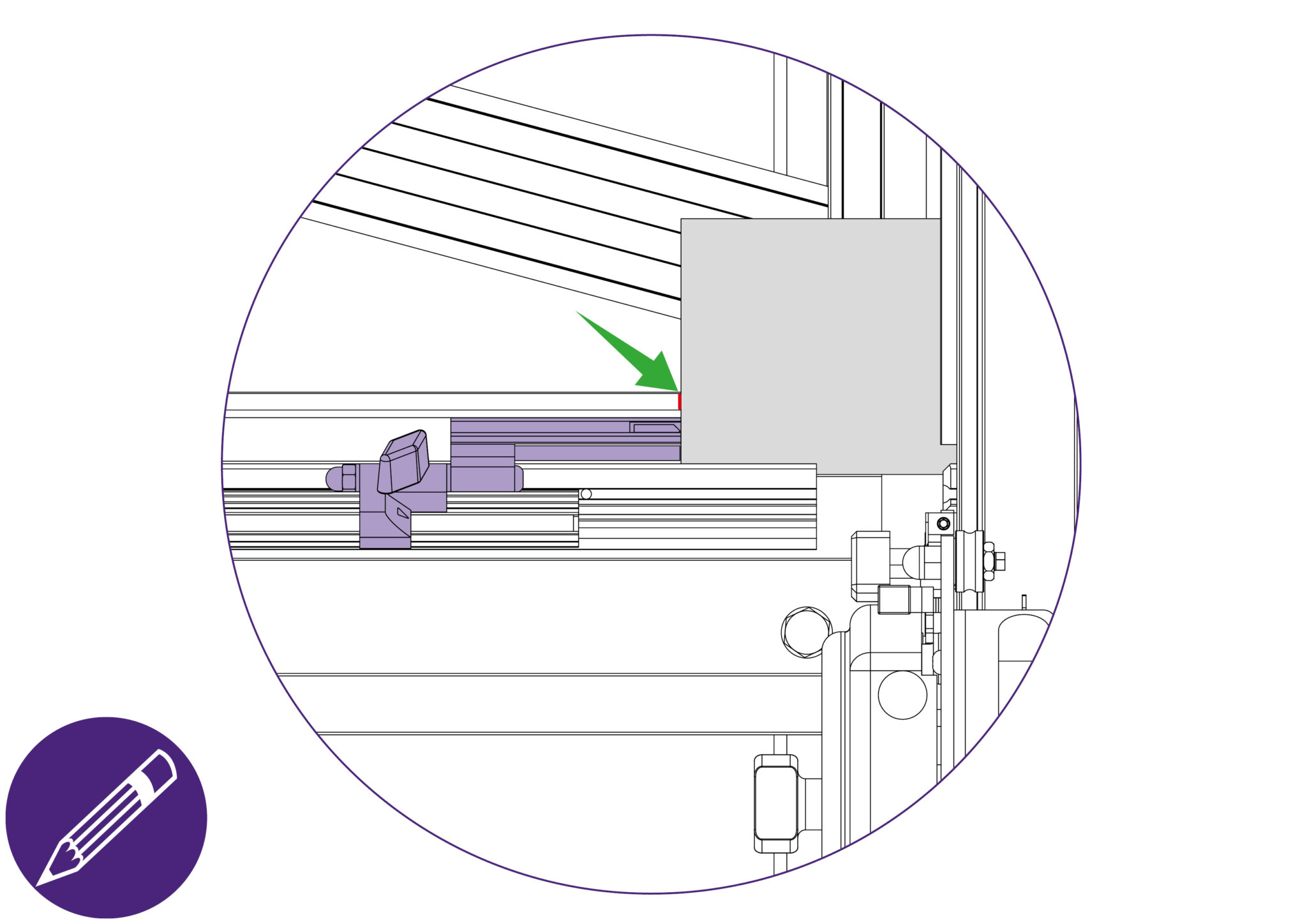
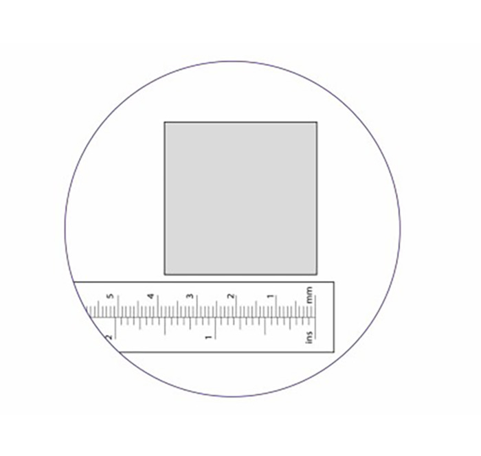
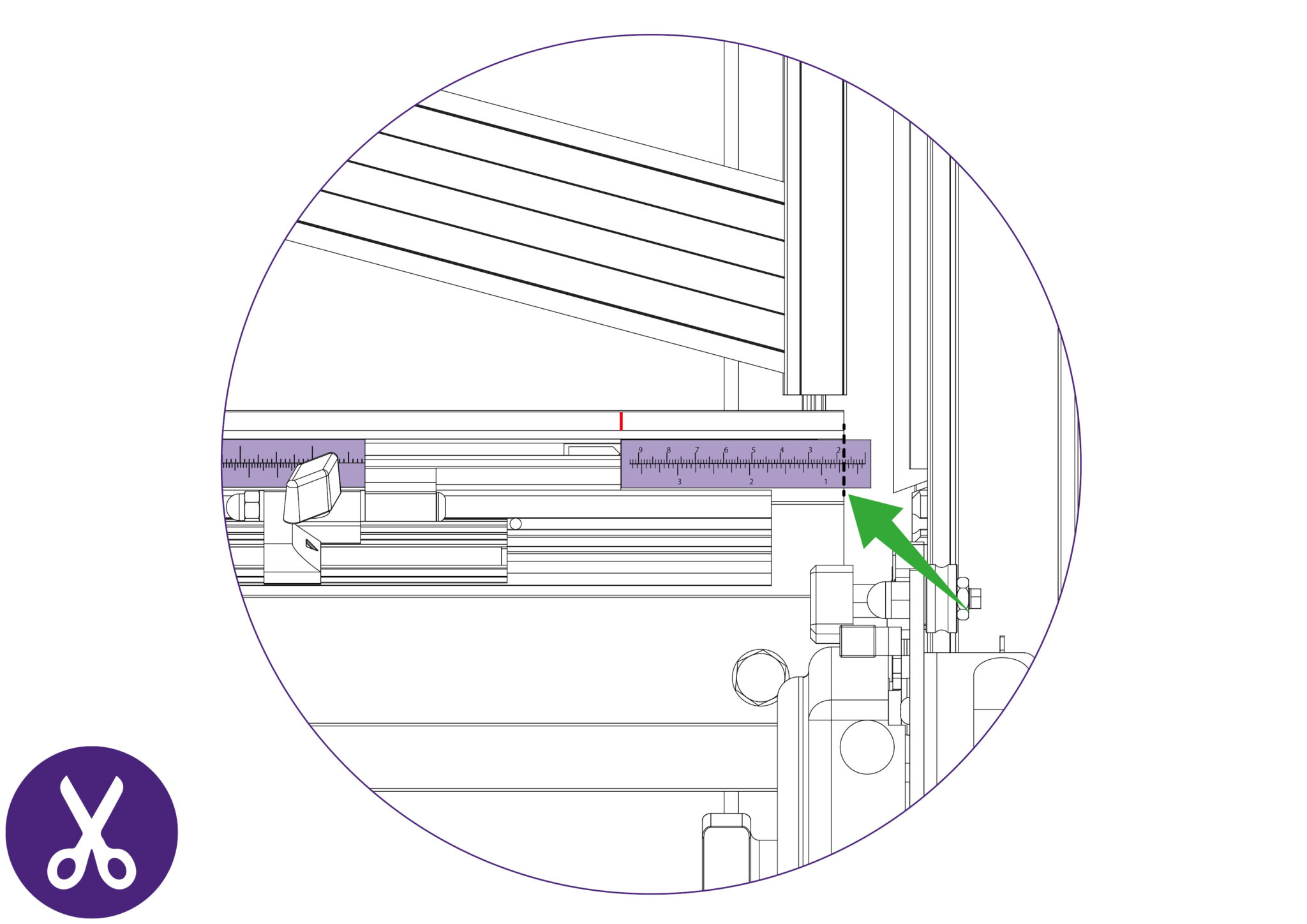
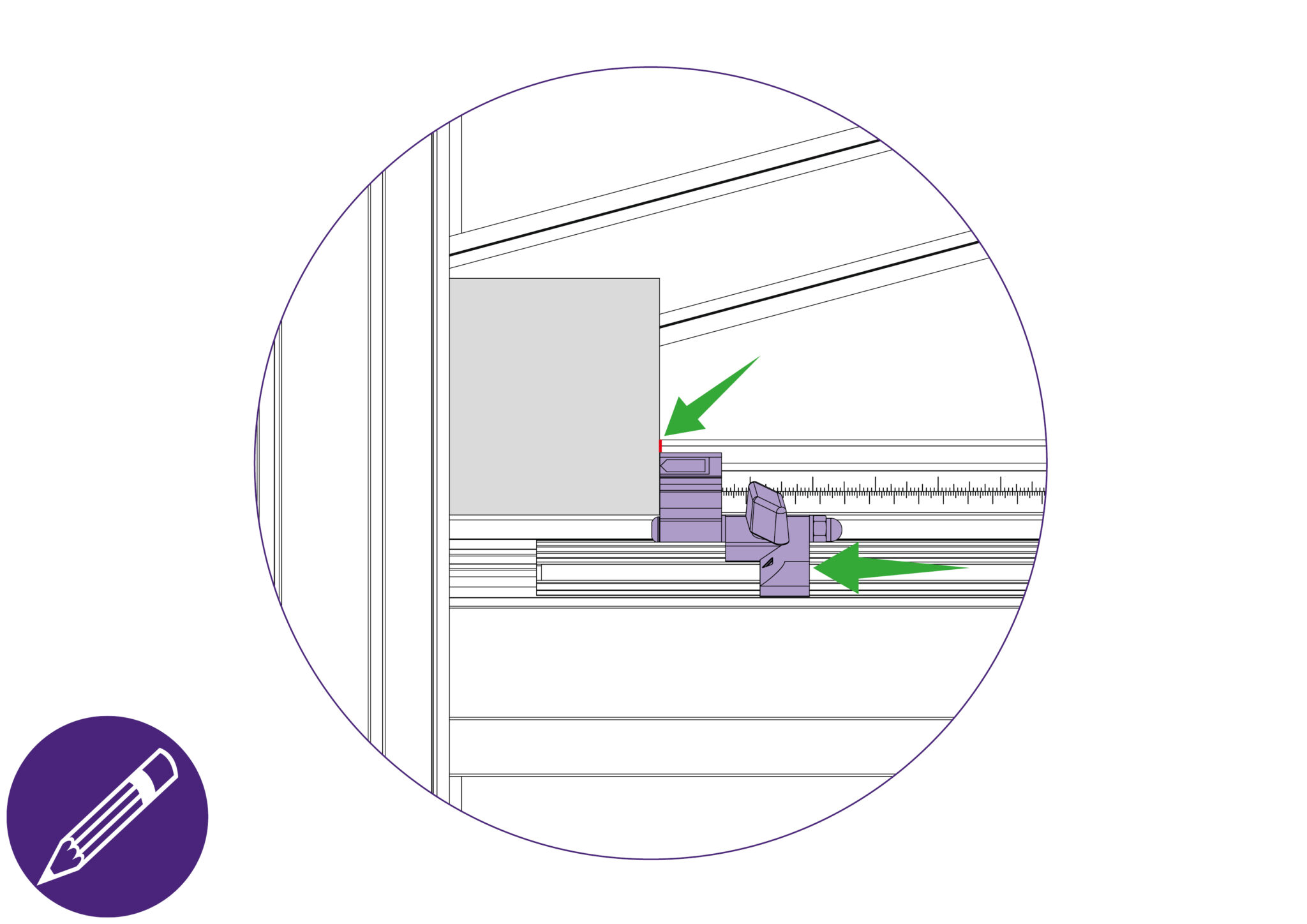
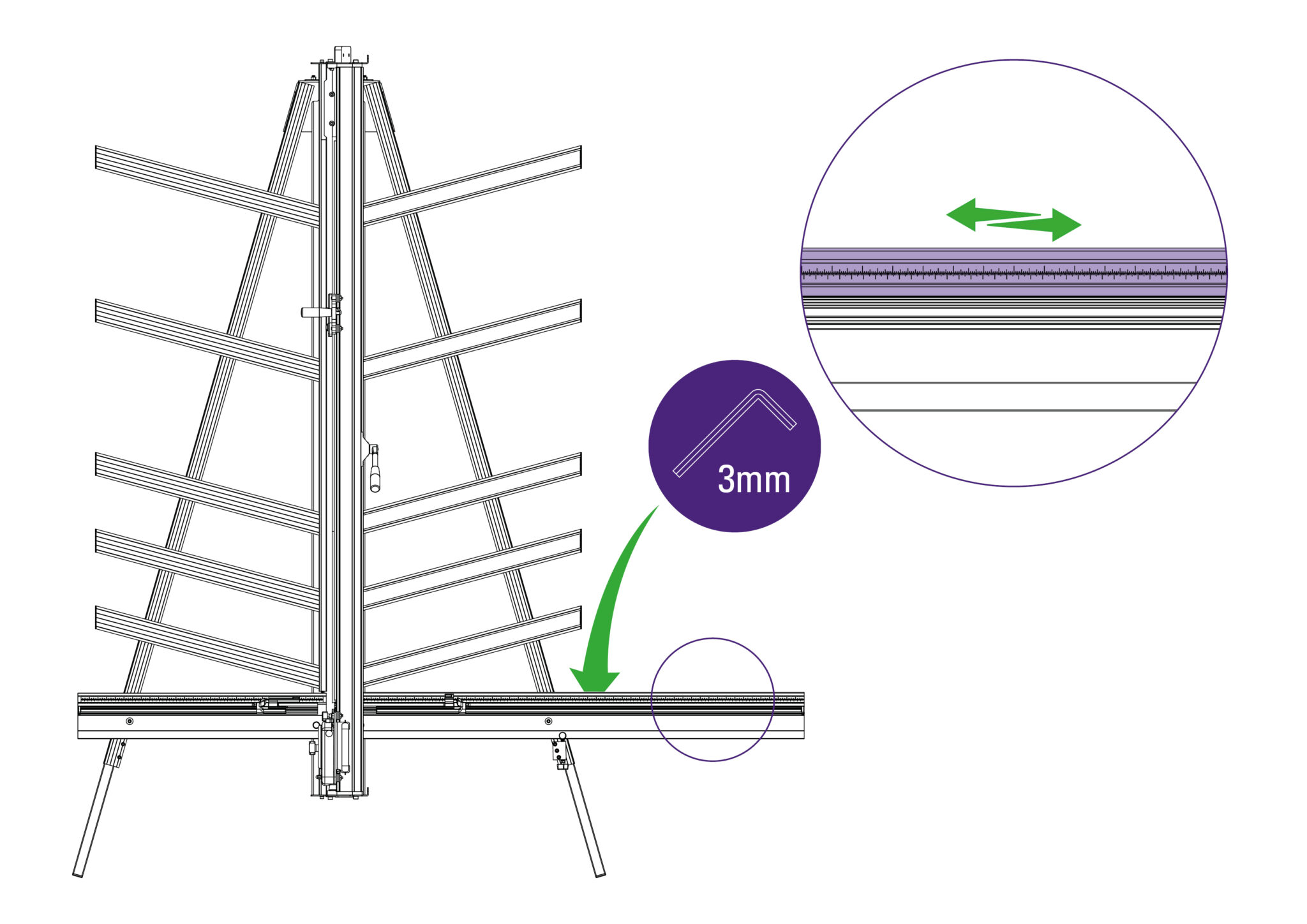
Cut the board and measure the width of the cut.
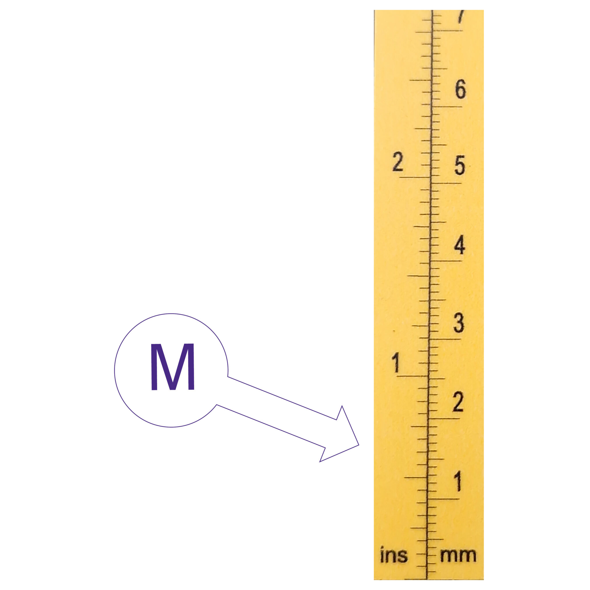
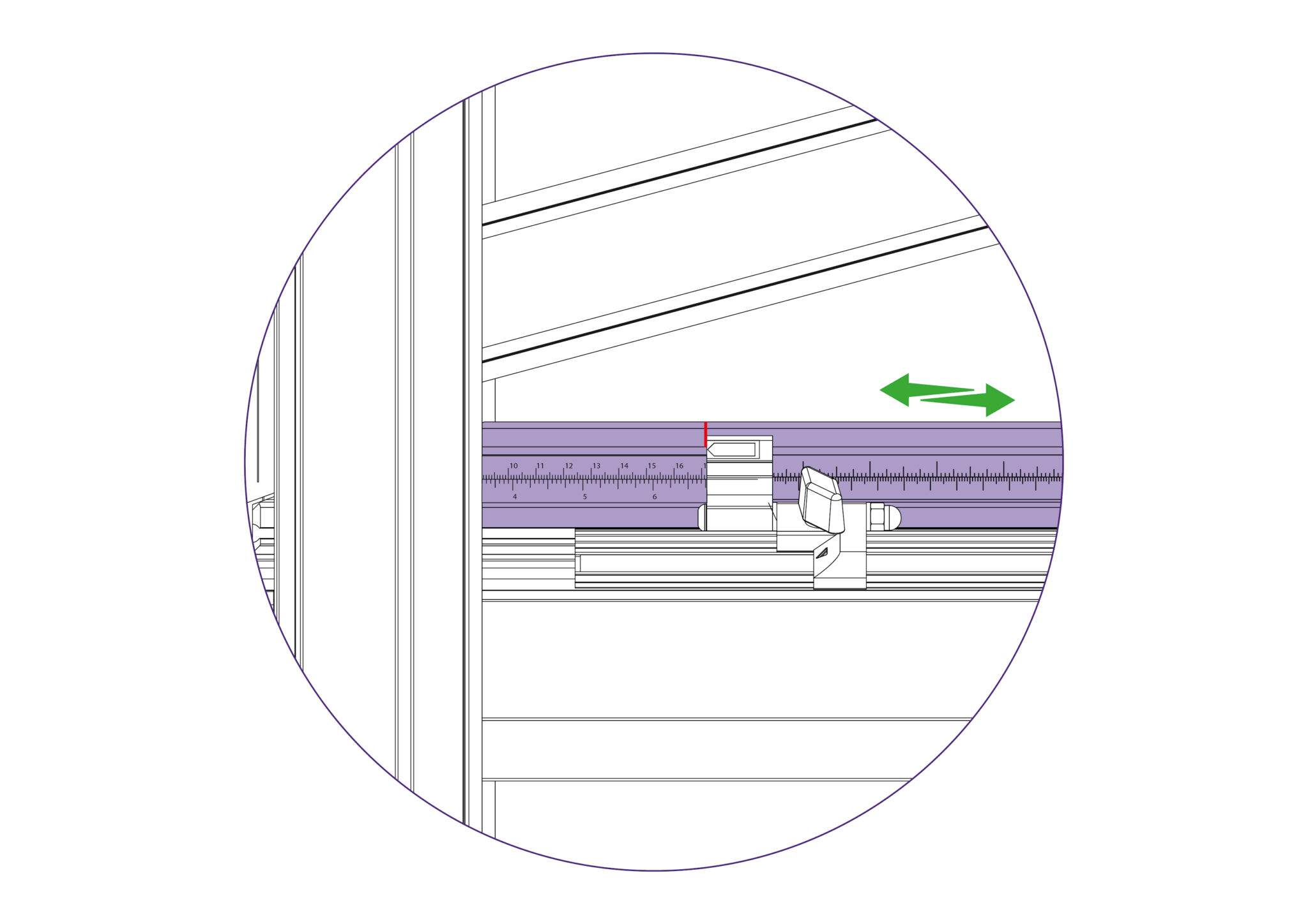
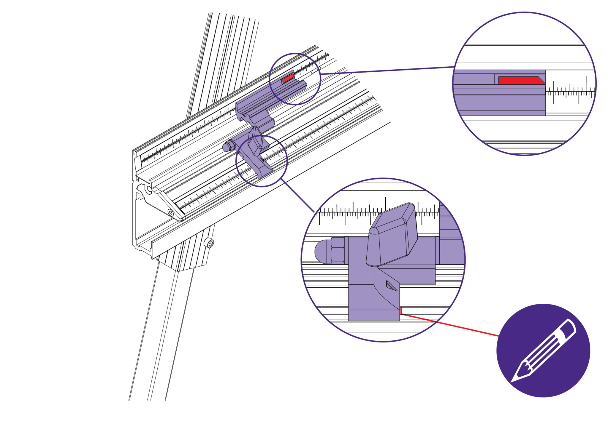
If the width of the cut board does not match the scale measurement that aligns with production stop, calibration would be required.
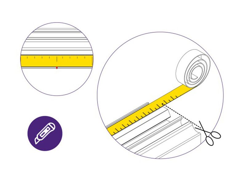
Otherwise, proceed to “Calibrating the Easy Measuring Scale”>.
Registering your Excalibur 6000 machine will activate your 5 year guarantee.
See the Excalibur 6000 User Guide for advice on cutting techniques, using the different cutting heads and care and maintenance of your machine.
To prevent injury and damage, lift the box and the machine with 2 people.
NOTE: When lifting the main body from the box, DO NOT lift using the black handles on the cutters.
If the installer expects to fix the machine to a wall instead of the Free-Standing Kit, suitable fixings will be required depending on the wall construction. Rawl plugs (as shown above) may accordingly not be a necessity.

Ⓒ Keencut 2026 | Baird Rd, Corby NN17 5ZA United Kingdom | Contact us
Created by DeType | Privacy | Website Disclaimer | Terms & Conditions


