
Evolution3 SmartFold Installation Manual – Finish assem and calibrate
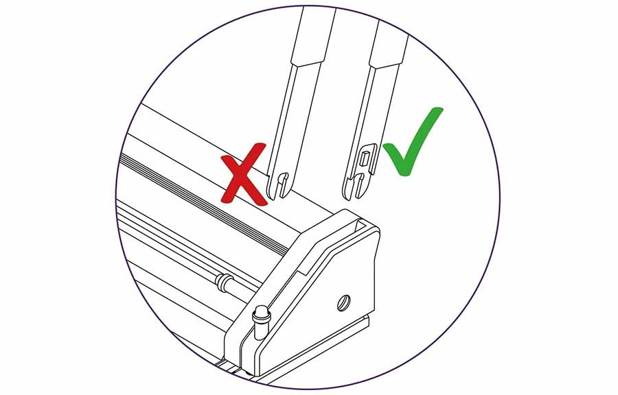
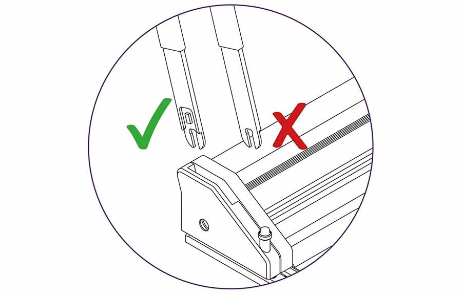
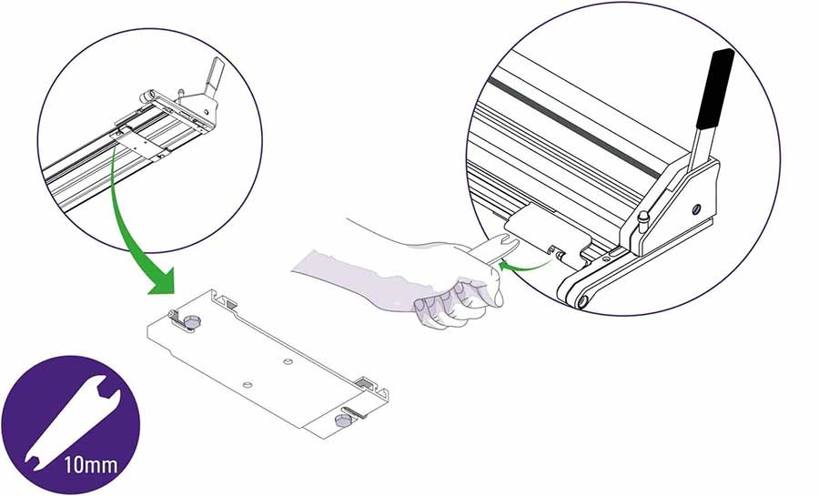
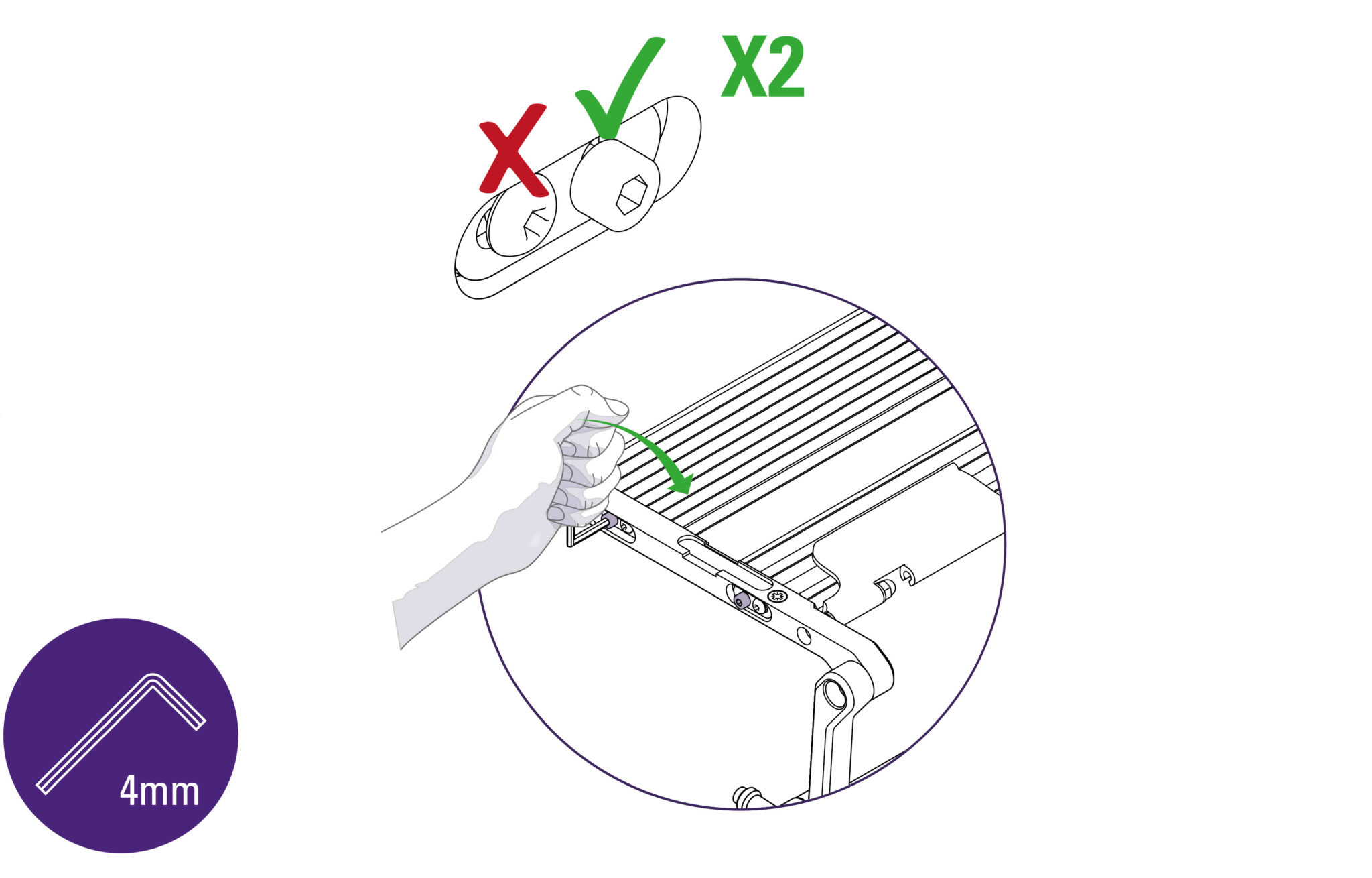
Ensure the flat face of the lever is facing to the centre of the unit.
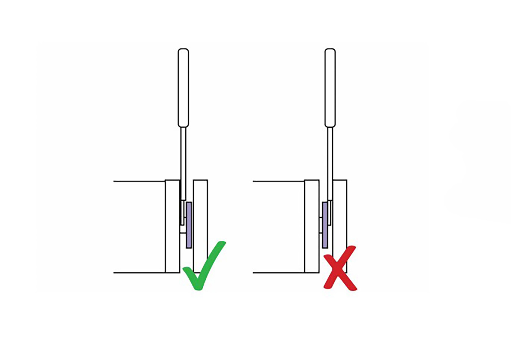
Insert the handle between the body of the cutter bar and the steel plate that can be seen within opening.
TIP: You can use the 3mm Allen key to move the steel plate within the opening if you are struggling to insert the handle.

Use the 5mm Allen (hex) key and insert it into highlighted section. Tighten fully.
| Do this firmly |
Repeat these steps on the other end again ensuring the flat face of the lever is facing to the centre of the unit and the handle is inserted between the body of the cutter bar and the steel plate. Tighten the fixing screw firmly.
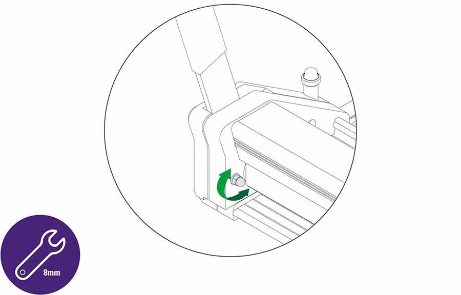
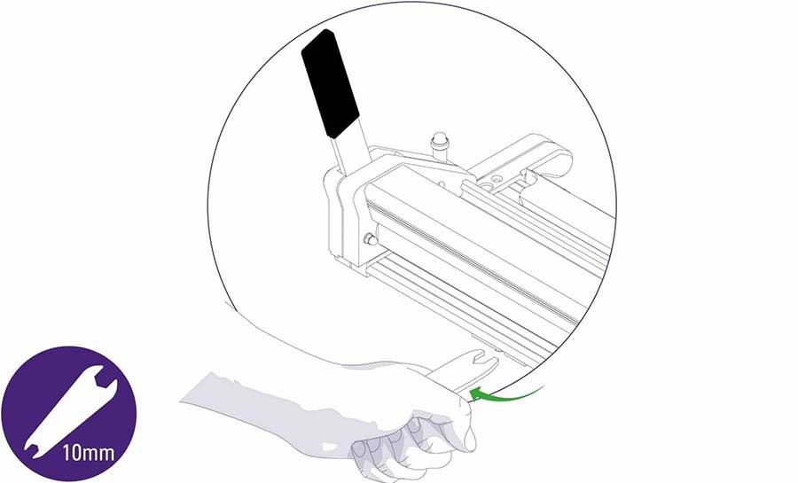
Use an 8mm spanner/wrench to adjust the highlighted nut to obtain the best setting to hold or hover the cutter bar above the base plate.
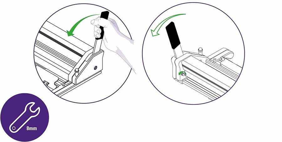
Loosen the nut a small amount, raise the cutter bar using the lever then carefully release the lever and the cutter bar should lower itself to the base plate. If not loosen the nut a small amount more.
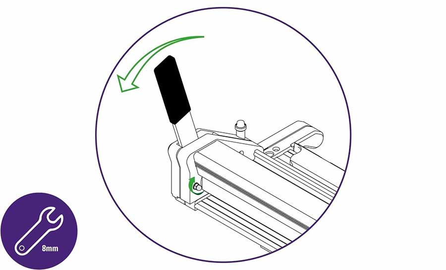
Raise the cutter bar and tighten the nut a very small amount until the cutter bar is held from falling.
Nudge the lever towards you in small movements, if the cutter bar then falls tighten the adjustment nut a very small amount and try again.
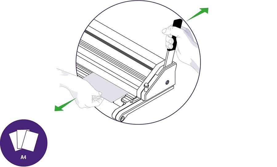
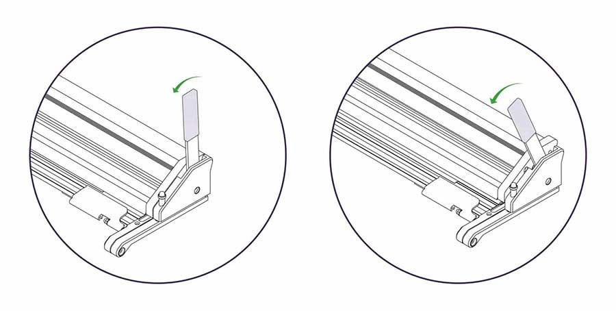
Insert a piece of A4/letter paper under the cutter bar at one end, push the lever away from you to fully lower the cutter bar. Test the paper is clamped by trying to move it.
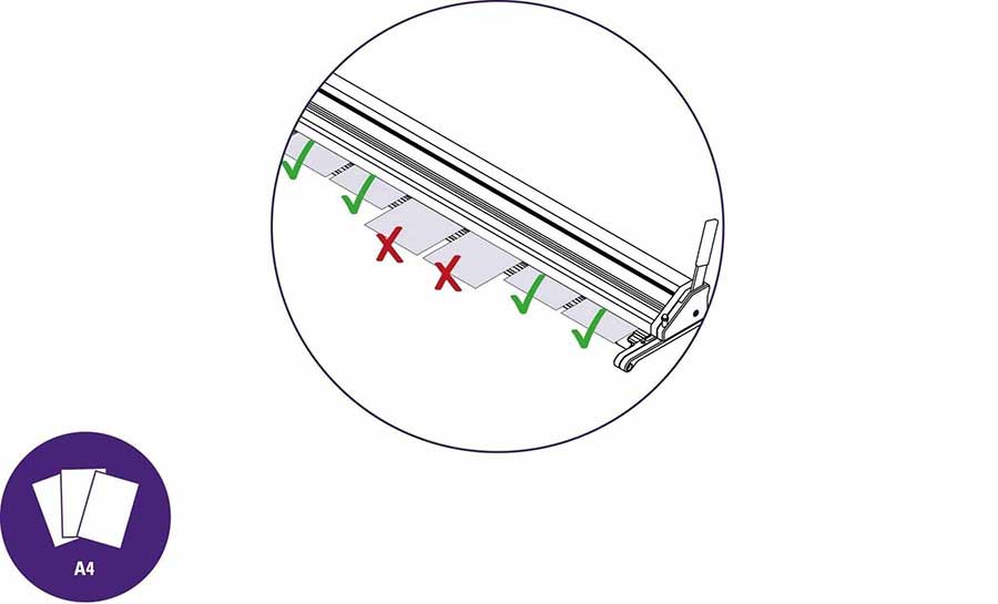
Repeat over the length of your SmartFold and take note of the areas where the paper moves when you pull it.
In those areas that the paper is not clamped, use the 10mm spanner/wrench to adjust the hex screws underneath the adjacent base brackets. There are two adjustment screws on each base bracket and they must both be adjusted by the same amount. Turn the hex screw just enough to correct the clamping in that area.
Access rear hex screw from the back of the machine. Adjust by the same amount as above.
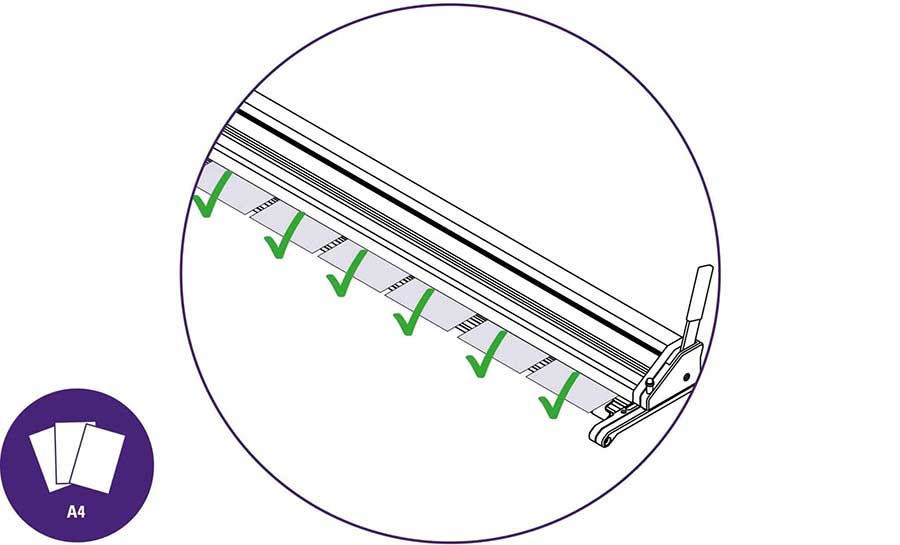
Repeat the clamping check along the whole length of the cutter bar, make further adjustments until the paper is clamped along the whole length of the machine.
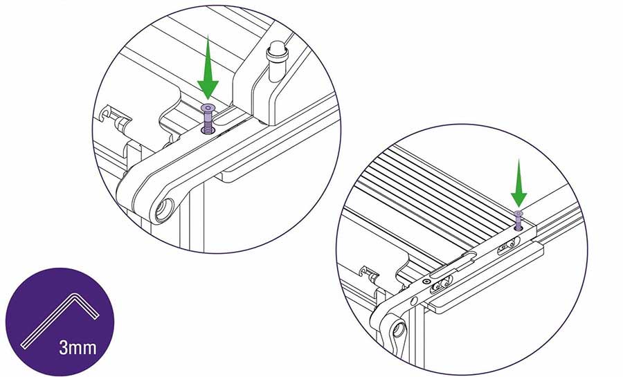
Using a Posi screwdriver (if fitting to custom made bench) or 3mm Allen (hex) key (if fitting to a SmartFold bench) fully tighten the vertical screws fixing the arm to the work surface (two at each end of the SmartFold).
Use 4mm Allen (hex) key to tighten the two cap screws, one located at each end of the SmartFold.
DO NOT loosen or tighten the red painted dome head bolts.
Repeat this step on the other end of your SmartFold.
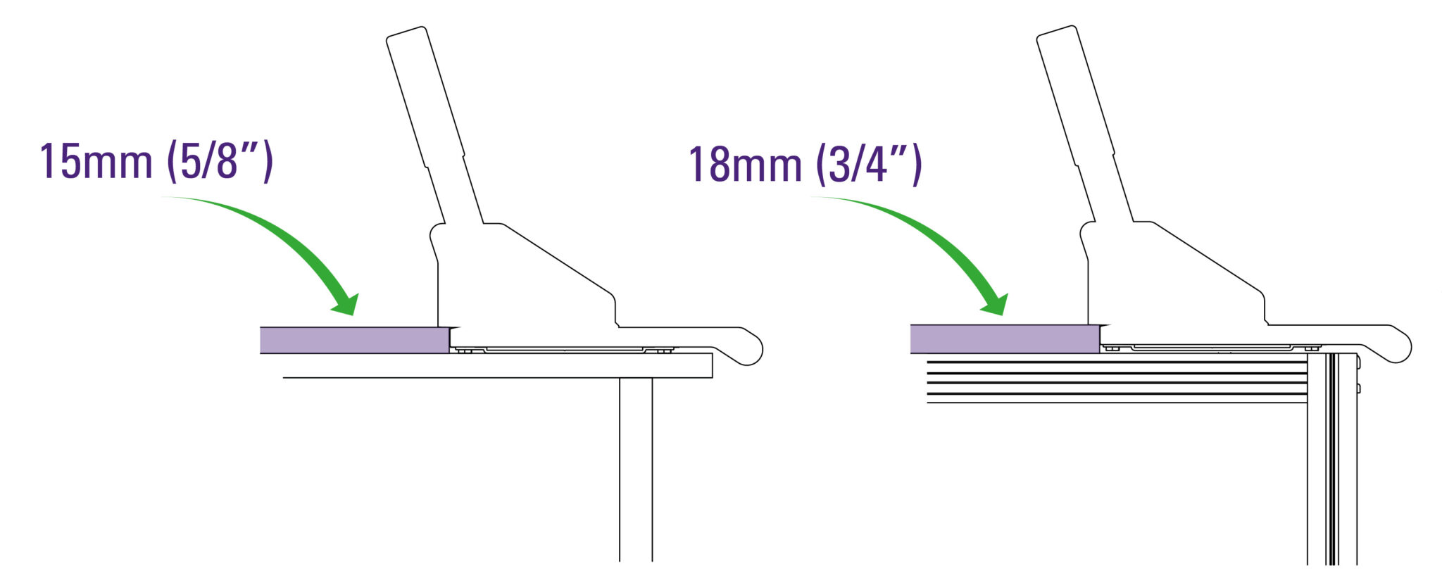
If fitting the SmartFold to a custom-made worksurface build the surface up behind the base plate by 15mm (⅝”) using MDF, plywood or similar, to level the work surface with that of the cutter.
When fitting to a SmartFold Bench, the 18mm (¾”) thick bench worktop should now be installed.
Ensure the flat face of the lever is facing to the centre of the unit.
Insert the handle between the body of the cutter bar and the steel plate that can be seen within opening.
TIP: You can use the 3mm Allen key to move the steel plate within the opening if you are struggling to insert the handle.
Use the 5mm Allen (hex) key and insert it into highlighted section. Tighten fully.
| Do this firmly |
Repeat these steps on the other end again ensuring the flat face of the lever is facing to the centre of the unit and the handle is inserted between the body of the cutter bar and the steel plate. Tighten the fixing screw firmly.
Use an 8mm spanner/wrench to adjust the highlighted nut to obtain the best setting to hold or hover the cutter bar above the base plate.
Loosen the nut a small amount, raise the cutter bar using the lever then carefully release the lever and the cutter bar should lower itself to the base plate. If not loosen the nut a small amount more.
Raise the cutter bar and tighten the nut a very small amount until the cutter bar is held from falling.
Nudge the lever towards you in small movements, if the cutter bar then falls tighten the adjustment nut a very small amount and try again.
Insert a piece of A4/letter paper under the cutter bar at one end, push the lever away from you to fully lower the cutter bar. Test the paper is clamped by trying to move it.
Repeat over the length of your SmartFold and take note of the areas where the paper moves when you pull it.
In those areas that the paper is not clamped, use the 10mm spanner/wrench to adjust the hex screws underneath the adjacent base brackets. There are two adjustment screws on each base bracket and they must both be adjusted by the same amount. Turn the hex screw just enough to correct the clamping in that area.
Access rear hex screw from the back of the machine. Adjust by the same amount as above.
Repeat the clamping check along the whole length of the cutter bar, make further adjustments until the paper is clamped along the whole length of the machine.
Using a Posi screwdriver (if fitting to custom made bench) or 3mm Allen (hex) key (if fitting to a SmartFold bench) fully tighten the vertical screws fixing the arm to the work surface (two at each end of the SmartFold).
Use 4mm Allen (hex) key to tighten the two cap screws, one located at each end of the SmartFold.
DO NOT loosen or tighten the red painted dome head bolts.
Repeat this step on the other end of your SmartFold.
If fitting the SmartFold to a custom-made worksurface build the surface up behind the base plate by 15mm (⅝”) using MDF, plywood or similar, to level the work surface with that of the cutter.
When fitting to a SmartFold Bench, the 18mm (¾”) thick bench worktop should now be installed.
Ⓒ Keencut 2020 | Baird Rd, Corby NN17 5ZA United Kingdom | Contact us
Created by DeType | Privacy | Website Disclaimer | Terms & Conditions