
Evolution3 SmartFold Installation Manual – SFB
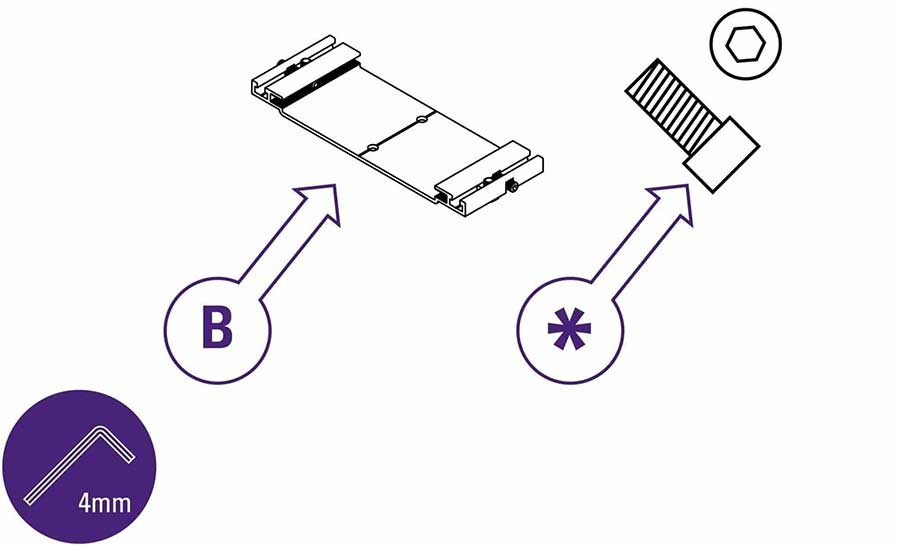
In this section you will need base brackets (part B) and short socket head screws (part * – delivered with the SmartFold Bench).
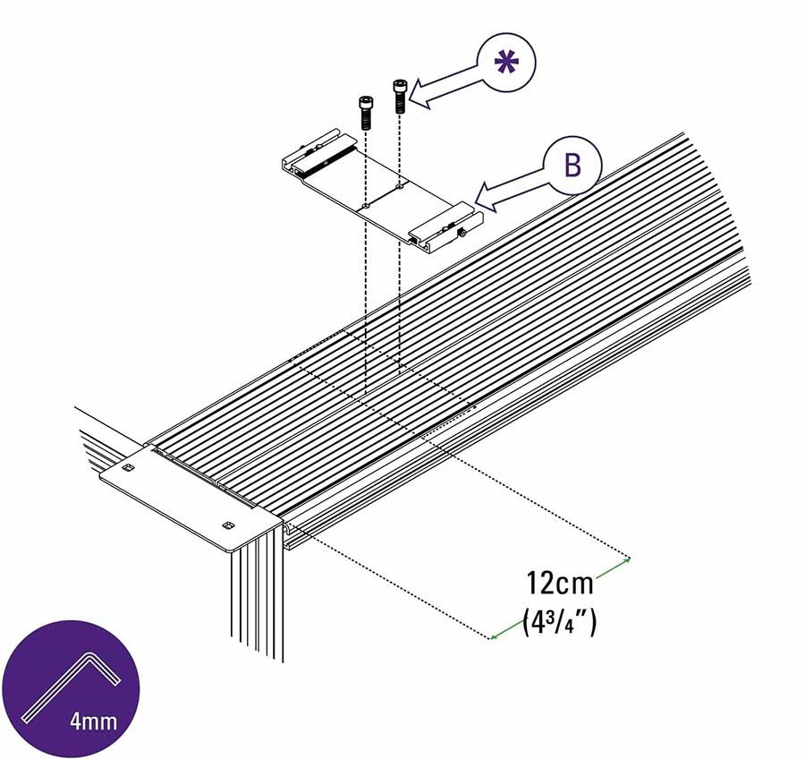
Place the first base bracket (part B) 12cm (4 3⁄4″) from the edge of your SmartFold Bench. Use the 4mm Allen (hex) key to tighten screws (part *).
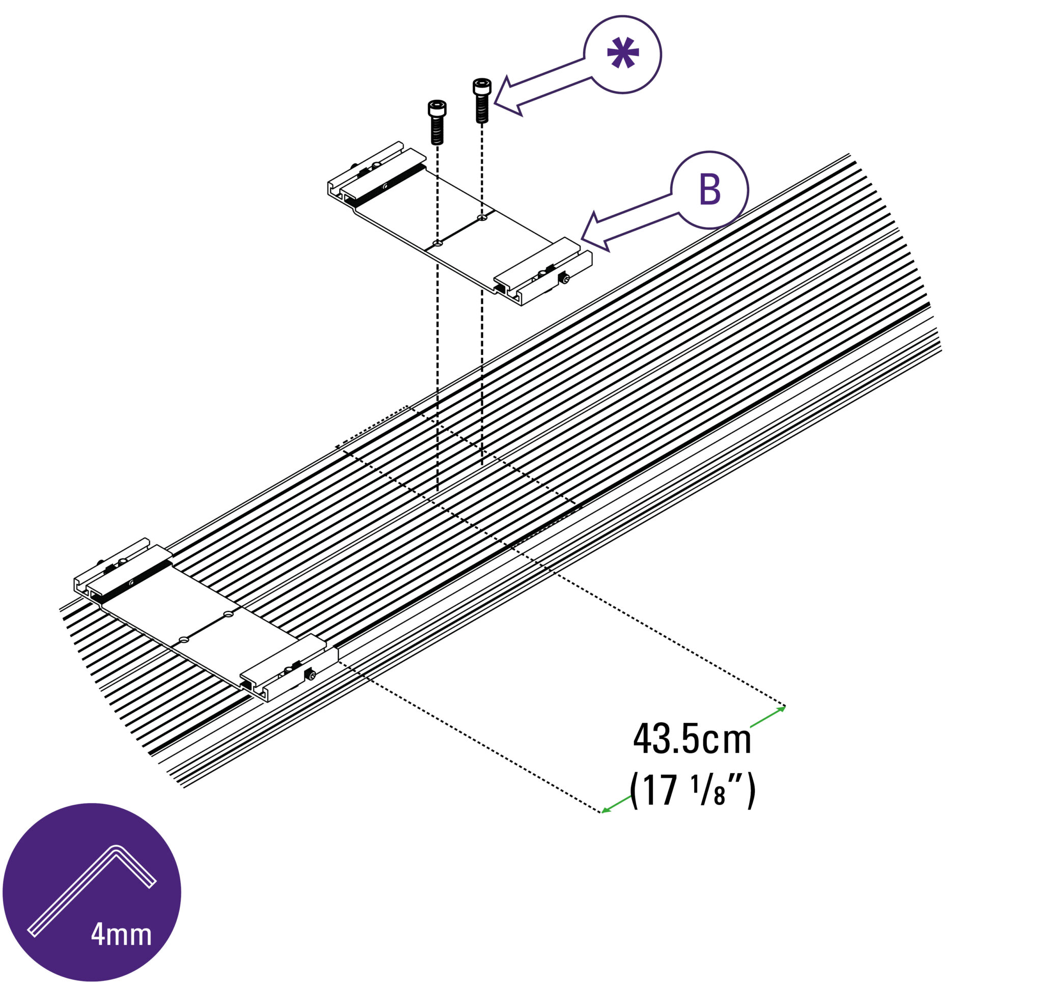
Place the following base brackets (part B) 43.5cm (17 ⅛”) from the edge of the previous base bracket. Use the 4mm Allen (hex) key to tighten screws (part *).
Continue placing the rest of the base brackets in this way.
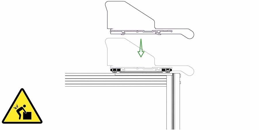
Centralise and lower the cutter slowly onto the base brackets.
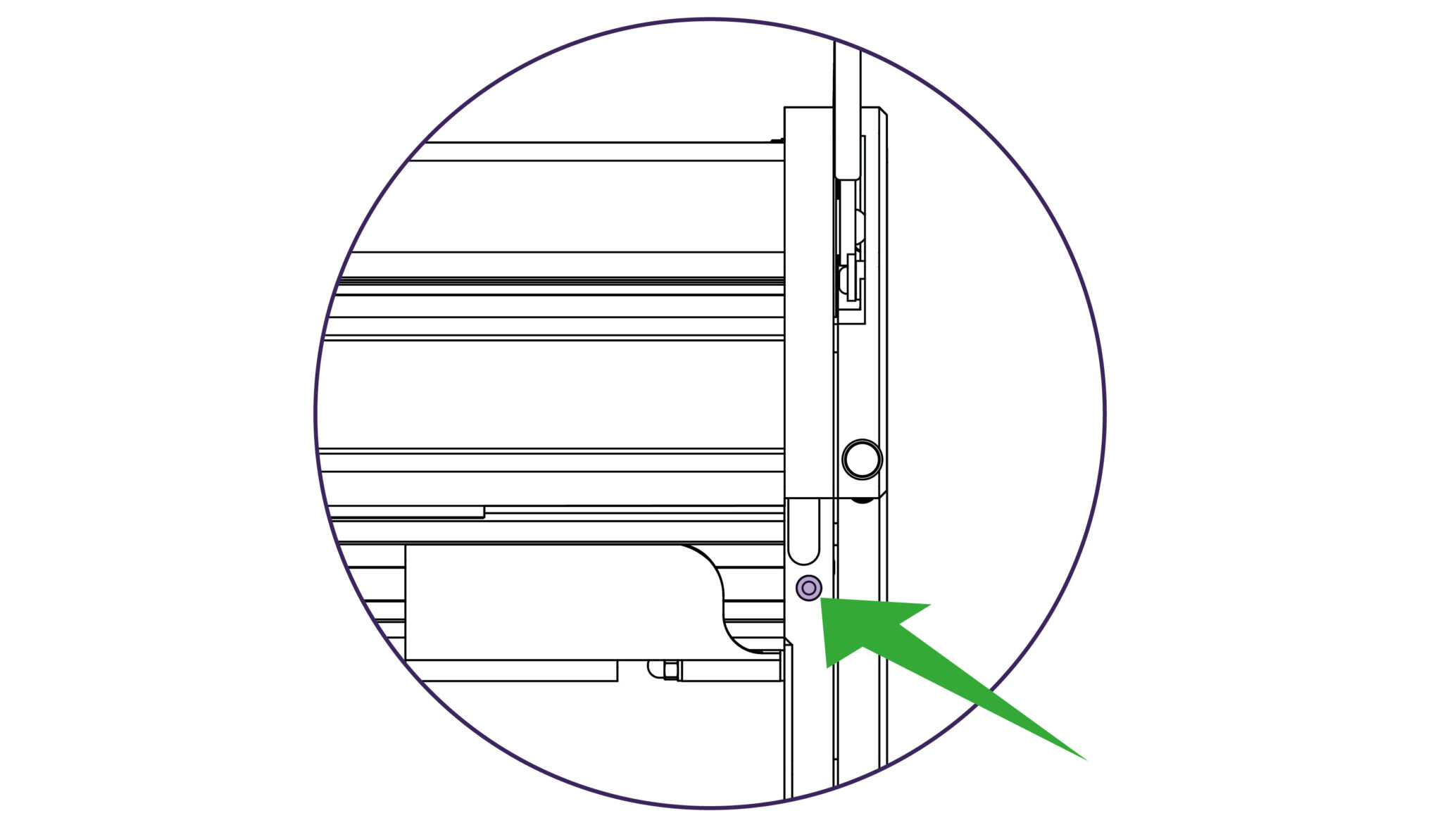
Ensure the holes on the arms of the cutter (highlighted in image) are aligned with the holes in the benches support plates.
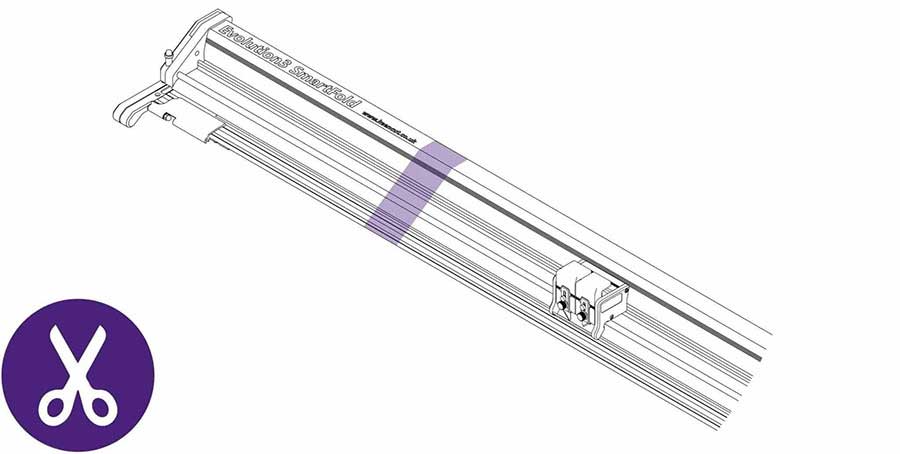
Once the SmartFold is in place, use scissors to remove the film packaging.
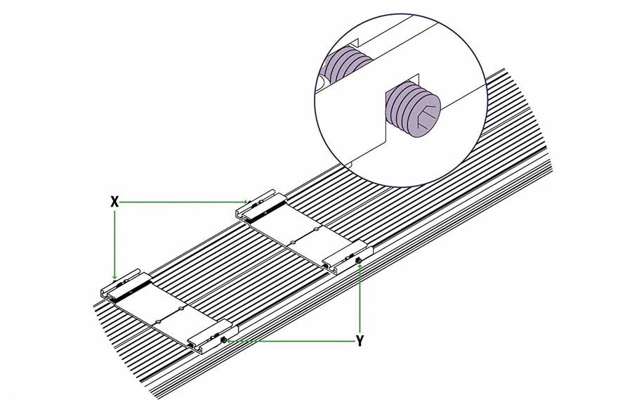
The base brackets have 2 grub screws each located at the front and the back (see ‘ x’ and ‘ y’).
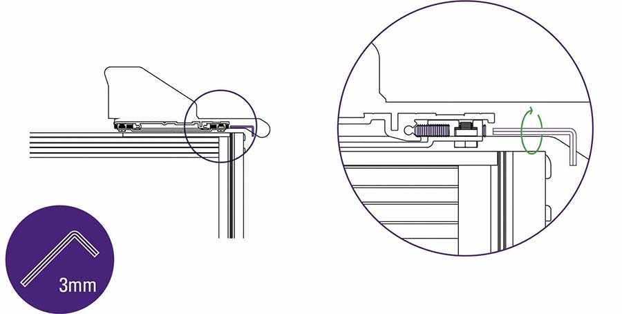
Use the long end of the 3mm Allen (hex) key rotate the grub screws in the front of the base brackets until you feel them come to a stop, do not tighten any further.
| Do this gently |
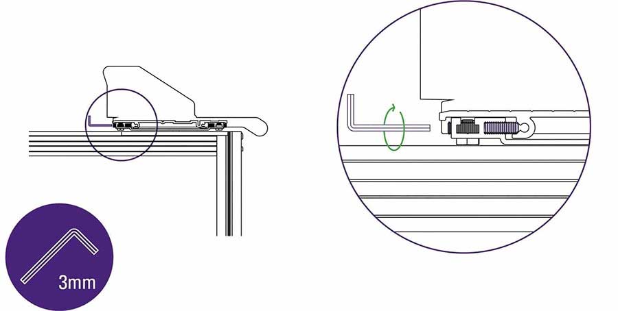
Repeat the process on the grub screws at the back of the base brackets.
| Do this gently |

Use the 3mm Allen (hex) key to firmly tighten the grub screws in the front of the base brackets.
| Do this firmly |
If you are attaching your SmartFold to an Evolution E2 Bench see section 2.4 to find out how to attach the cutter arms to an Evolution E2 Bench >
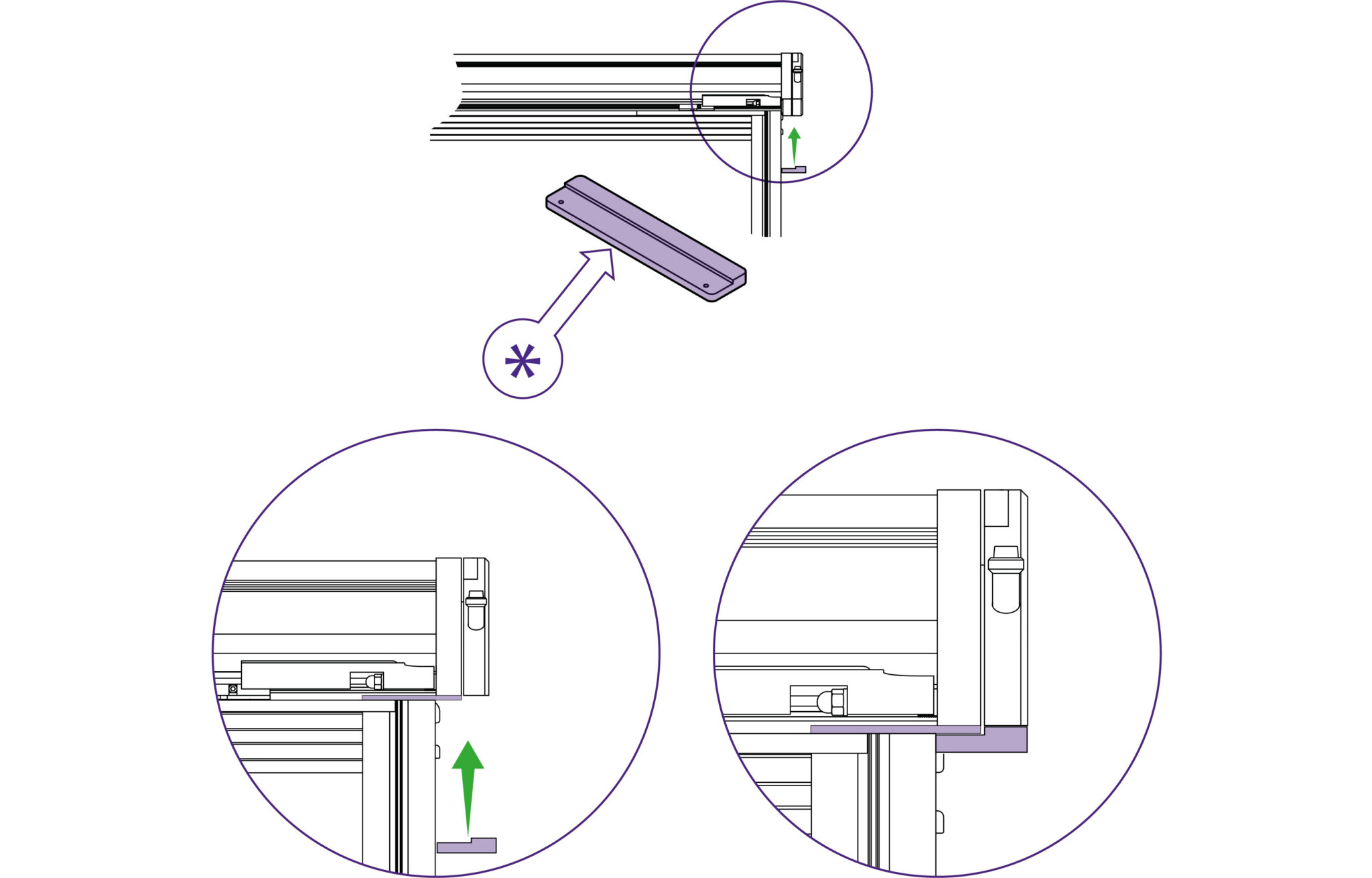
If the black brackets support both arms of the cutter use the black steel bar (part * – supplied with the SmartFold Bench).

Pass the long countersink screw (supplied with the bench) through the arm and black support bracket then use the 2.5mm Allen (hex) key to loosely attach into the clamp bar. Repeat the step on the other side of your machine.
| Do this gently |
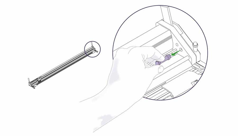
Pull and remove end stop.
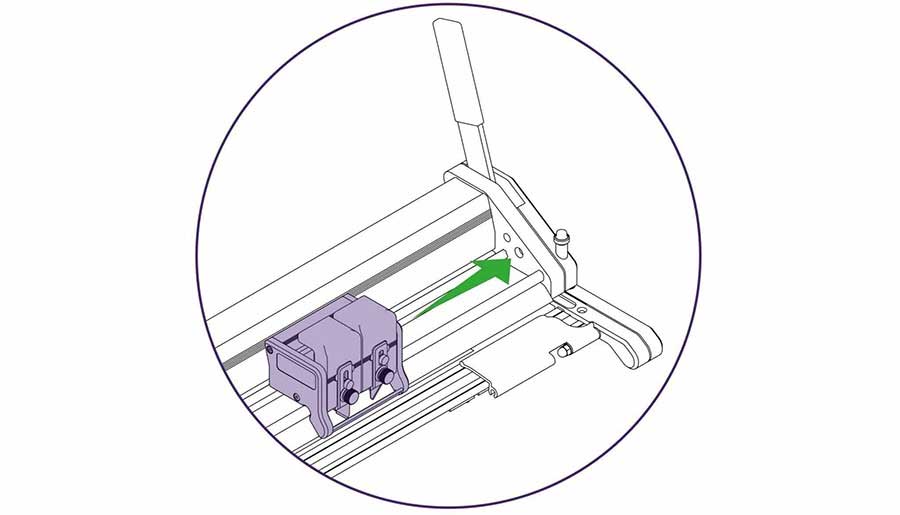
Slide the cutting head to the right.
Gently lift to remove the cutter head, then replace end stop.
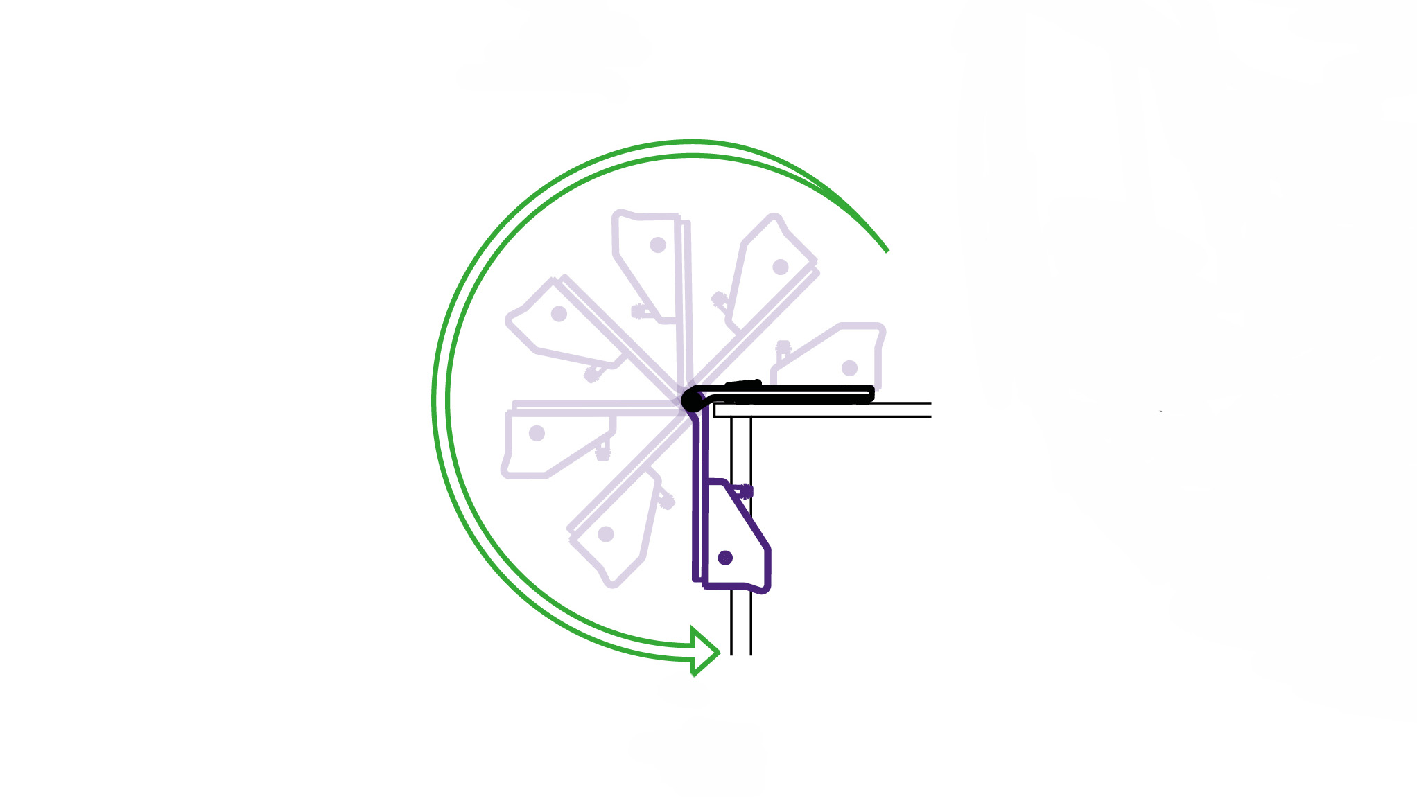
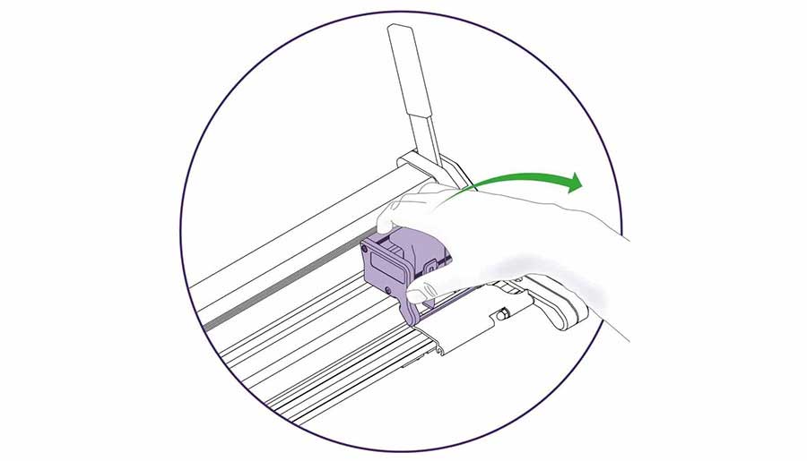
Grip the cutter bar firmly, lift carefully and swing over the edge of the bench, bring gently to a stop when vertical.
| Be careful when lifting |
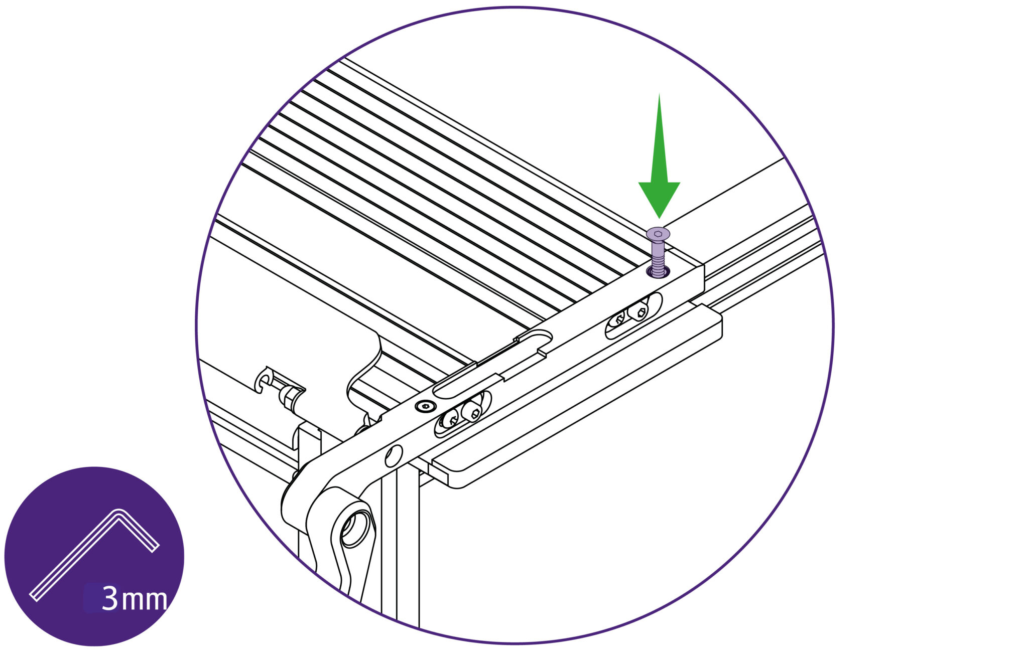
Insert long countersink screw (supplied with the bench) but do not fully tighten. Repeat this step on the other side of your SmartFold.
| Do this gently |
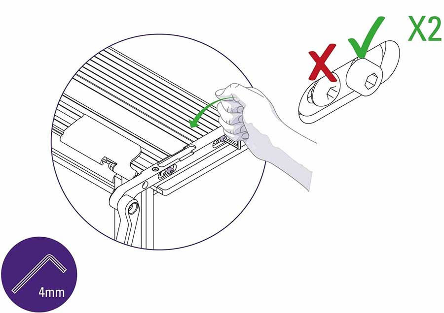
Use 4mm Allen (hex) Key to loosen the cap screws by one full turn at the end of the SmartFold.
DO NOT loosen the domed head screws that have red paint on them.
Repeat this step on the other end of your SmartFold.
Next step:
If you are attaching your SmartFold to an Evolution3 SmartFold Bench see section 2.3 to find out how to attach the cutter arms to an Evolution3 SmartFold Bench >
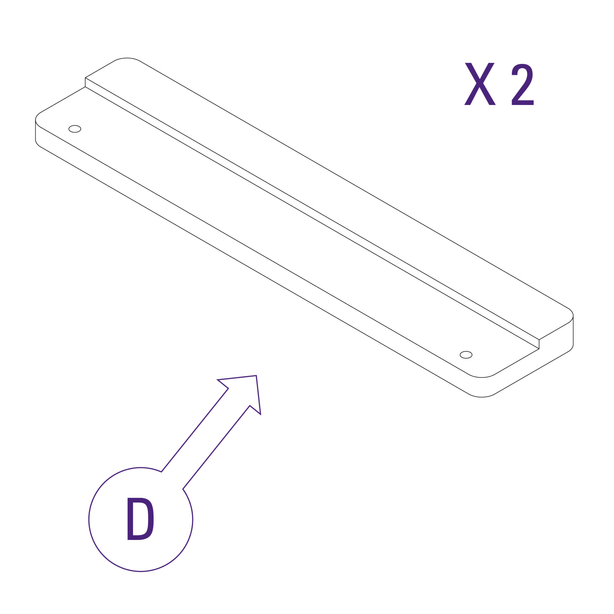
You will need this part to attach your SmartFold to an Evolution2 Bench.

Lift the stepped clamp bar (part D) into position as shown.
Pass the long countersink screw (supplied with the bench) through the arm and black support bracket then use the 2.5mm Allen (hex) key to loosely attach into the clamp bar. Repeat the step on the other side of your machine.
| Do this gently |
Pull and remove end stop.
Slide the cutting head to the right.
Gently lift to remove the cutter head, then replace end stop.
Grip the cutter bar firmly, lift carefully and swing over the edge of the bench, bring gently to a stop when vertical.
| Be careful when lifting |
Insert long countersink screw (supplied with the bench) but do not fully tighten. Repeat this step on the other side of your SmartFold.
| Do this gently |
Use 4mm Allen (hex) Key to loosen the cap screws by one full turn at the end of the SmartFold.
DO NOT loosen the domed head screws that have red paint on them.
Repeat this step on the other end of your SmartFold.
Next step:
In this section you will need base brackets (part B) and short socket head screws (part * – delivered with the SmartFold Bench).
Place the first base bracket (part B) 12cm (4 3⁄4″) from the edge of your SmartFold Bench. Use the 4mm Allen (hex) key to tighten screws (part *).
Place the following base brackets (part B) 43.5cm (17 ⅛”) from the edge of the previous base bracket. Use the 4mm Allen (hex) key to tighten screws (part *).
Continue placing the rest of the base brackets in this way.
Centralise and lower the cutter slowly onto the base brackets.
Ensure the holes on the arms of the cutter (highlighted in image) are aligned with the holes in the benches support plates.
Once the SmartFold is in place, use scissors to remove the film packaging.
The base brackets have 2 grub screws each located at the front and the back (see ‘ x’ and ‘ y’).
Use the long end of the 3mm Allen (hex) key rotate the grub screws in the front of the base brackets until you feel them come to a stop, do not tighten any further.
| Do this gently |
Repeat the process on the grub screws at the back of the base brackets.
| Do this gently |
Use the 3mm Allen (hex) key to firmly tighten the grub screws in the front of the base brackets.
| Do this firmly |
If you are attaching your SmartFold to an Evolution E2 Bench see section 2.4 to find out how to attach the cutter arms to an Evolution E2 Bench >
If the black brackets support both arms of the cutter use the black steel bar (part * – supplied with the SmartFold Bench).
Pass the long countersink screw (supplied with the bench) through the arm and black support bracket then use the 2.5mm Allen (hex) key to loosely attach into the clamp bar. Repeat the step on the other side of your machine.
| Do this gently |
Pull and remove end stop.
Slide the cutting head to the right.
Gently lift to remove the cutter head, then replace end stop.
Grip the cutter bar firmly, lift carefully and swing over the edge of the bench, bring gently to a stop when vertical.
| Be careful when lifting |
Insert long countersink screw (supplied with the bench) but do not fully tighten. Repeat this step on the other side of your SmartFold.
| Do this gently |
Use 4mm Allen (hex) Key to loosen the cap screws by one full turn at the end of the SmartFold.
DO NOT loosen the domed head screws that have red paint on them.
Repeat this step on the other end of your SmartFold.
Next step:
If you are attaching your SmartFold to an Evolution3 SmartFold Bench see section 2.3 to find out how to attach the cutter arms to an Evolution3 SmartFold Bench >
You will need this part to attach your SmartFold to an Evolution2 Bench.
Lift the stepped clamp bar (part D) into position as shown.
Pass the long countersink screw (supplied with the bench) through the arm and black support bracket then use the 2.5mm Allen (hex) key to loosely attach into the clamp bar. Repeat the step on the other side of your machine.
| Do this gently |
Pull and remove end stop.
Slide the cutting head to the right.
Gently lift to remove the cutter head, then replace end stop.
Grip the cutter bar firmly, lift carefully and swing over the edge of the bench, bring gently to a stop when vertical.
| Be careful when lifting |
Insert long countersink screw (supplied with the bench) but do not fully tighten. Repeat this step on the other side of your SmartFold.
| Do this gently |
Use 4mm Allen (hex) Key to loosen the cap screws by one full turn at the end of the SmartFold.
DO NOT loosen the domed head screws that have red paint on them.
Repeat this step on the other end of your SmartFold.
Next step:
Ⓒ Keencut 2020 | Baird Rd, Corby NN17 5ZA United Kingdom | Contact us
Created by DeType | Privacy | Website Disclaimer | Terms & Conditions