
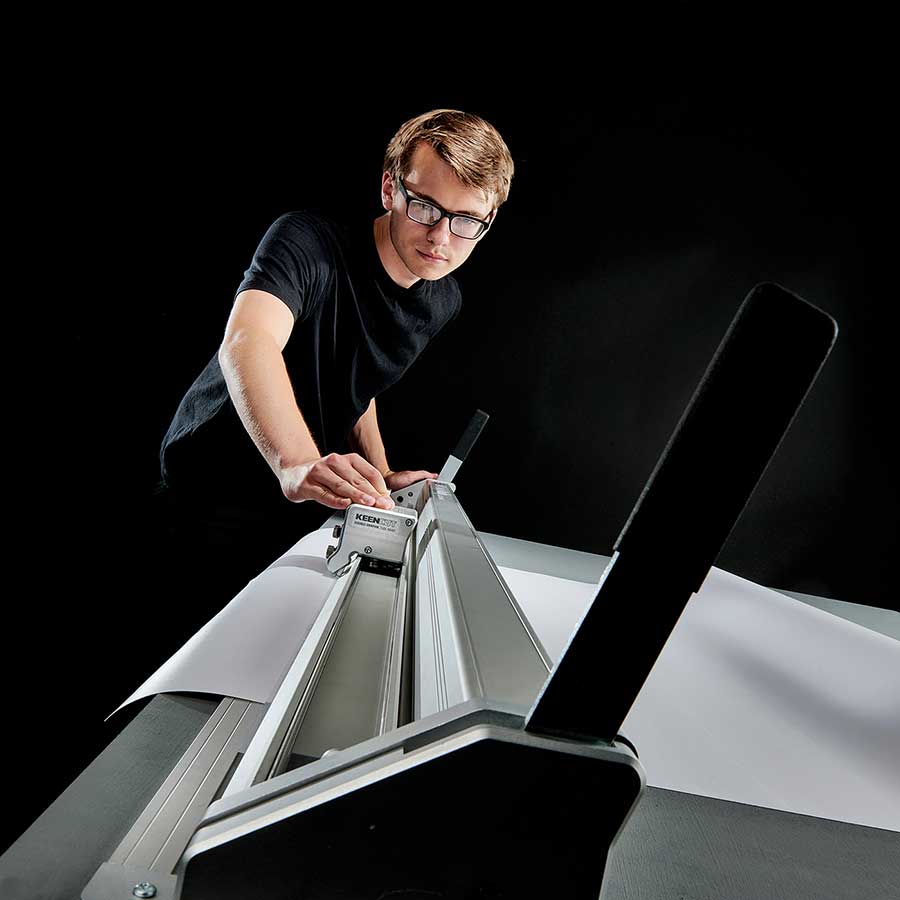

Evolution3 BenchTop User Guide
How to use this guide
Scroll down to view the guide.
You can expand and collapse sections using the + and – icons.
View PDF version >
Other support resources
Register your cutter to activate your guarantee >
Visit Keencut support centre >
Visit user forum
Contact Keencut >
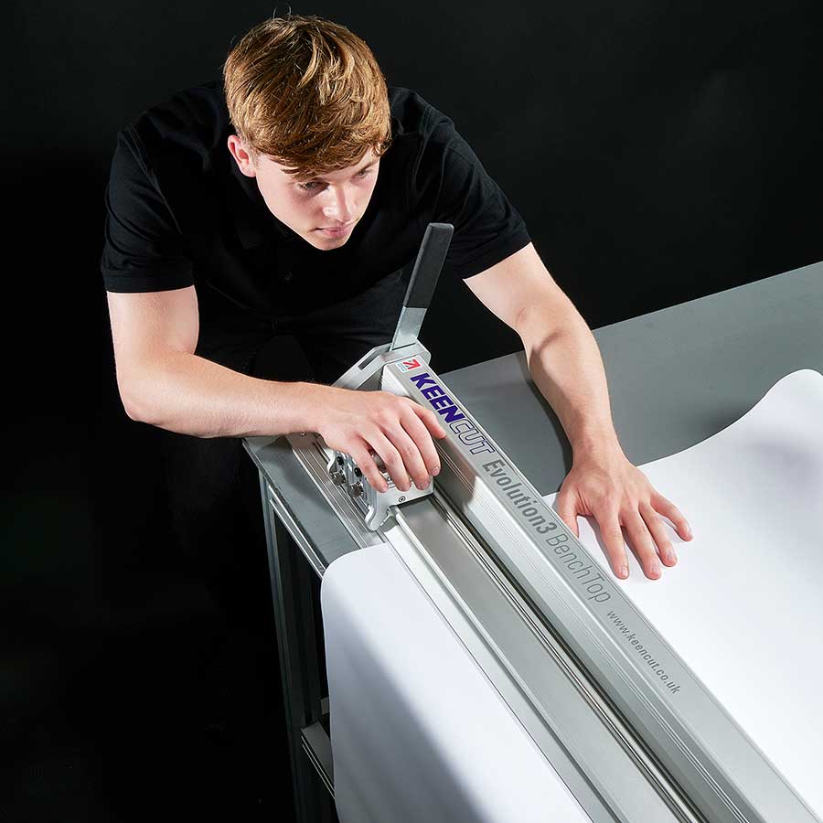
This User Guide for the Evolution3 BenchTop gives advice on cutting techniques, using the different cutting heads and care and maintenance of your machine.
Before using your machine make sure that you have installed and calibrated it correctly. Full details are in the Installation Manual.
The patented ‘Lift-and-Hover’ is a unique Keencut development that combines three features to give the ultimate in accuracy and productivity.
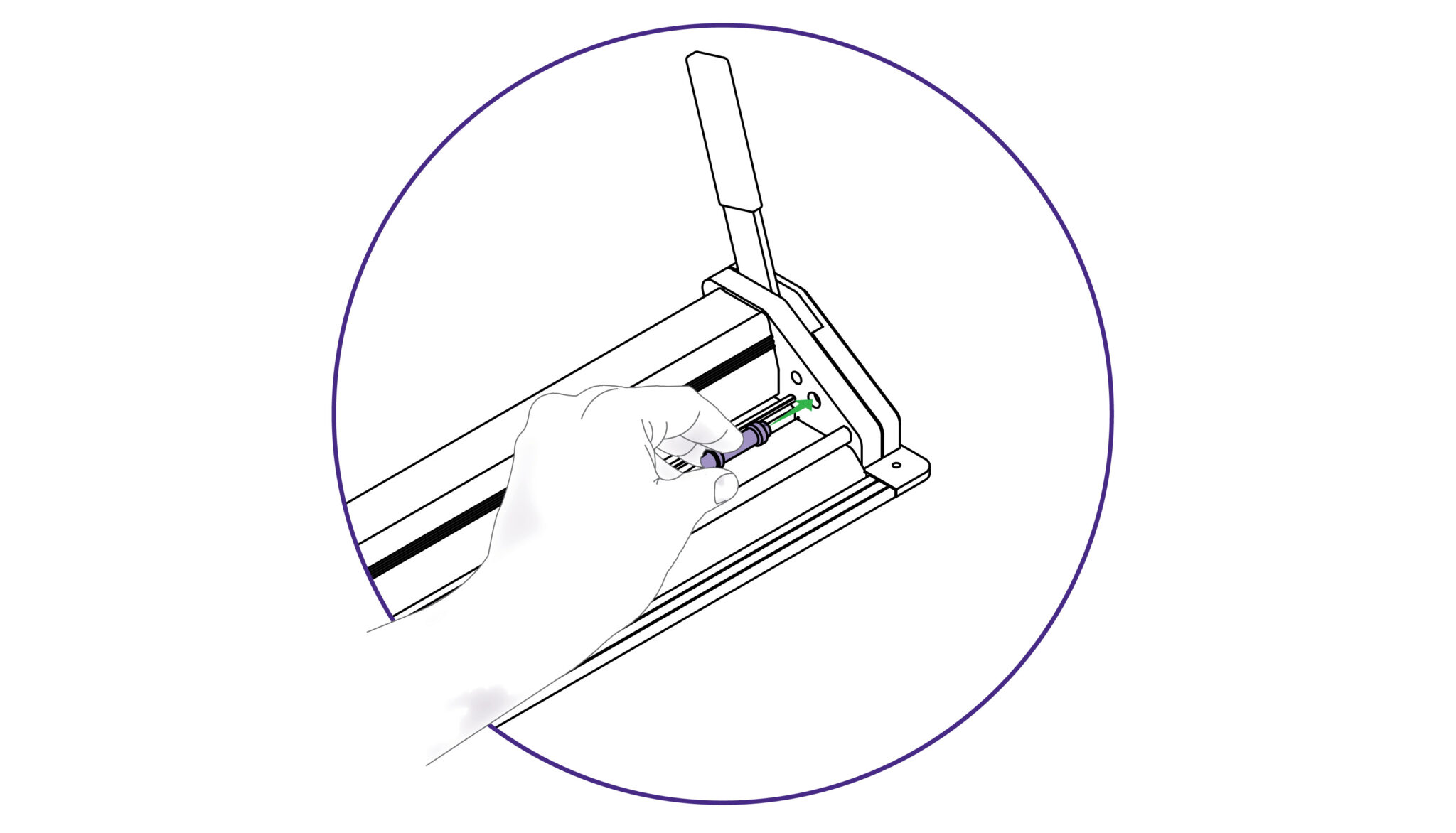
The BenchTop can hold the whole length of the cutter bar a very short distance above the object being trimmed and hold it there even if the levers are released. This leaves both hands free to align the objects cutting marks to the edge of the sightline strip. Pushing either lever fully lowers the cutter bar and clamps the object ready for cutting.
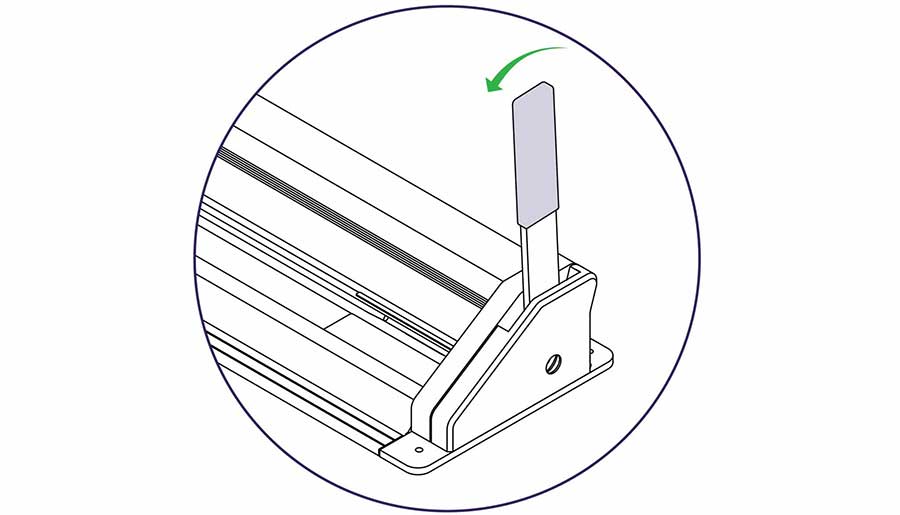
Hover action – See how to adjust the hover action >
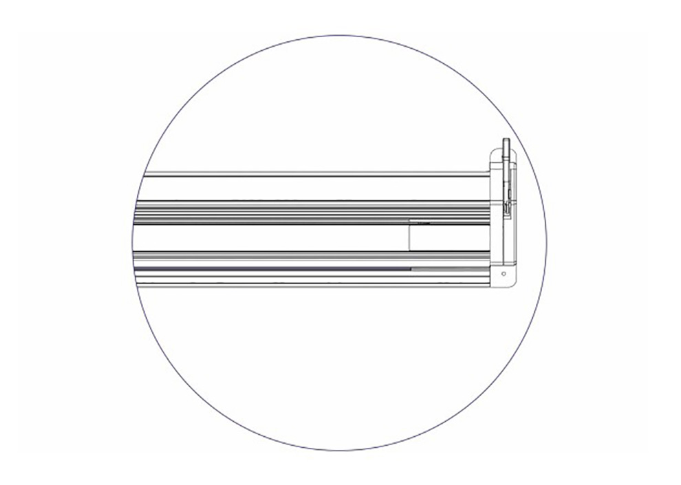
Sightline strip – These are easily replaceable and are available from your supplier.
See how to replace the sightline strip >
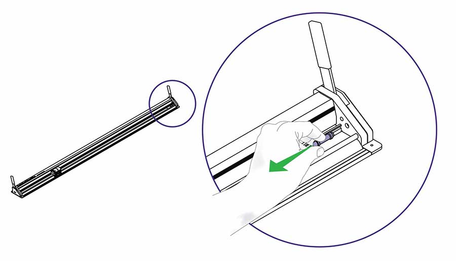
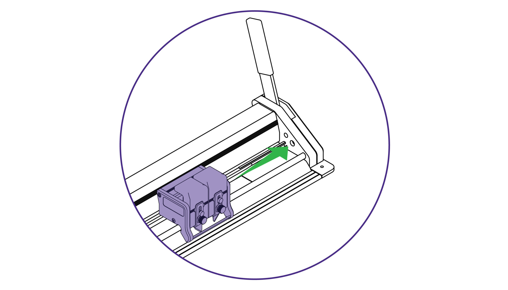
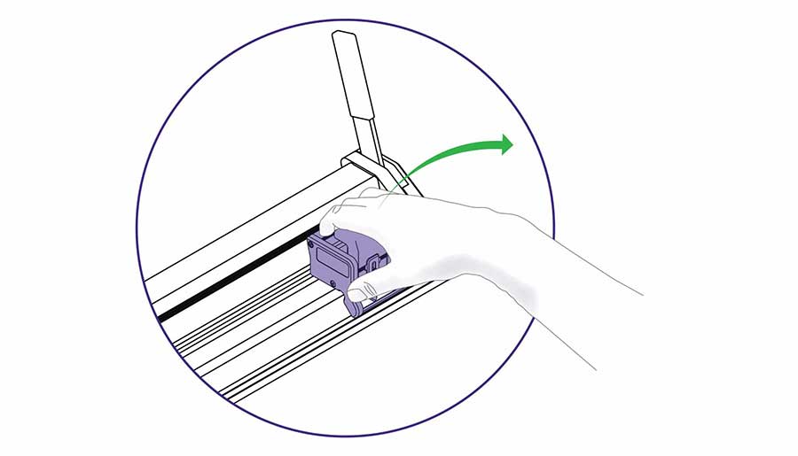
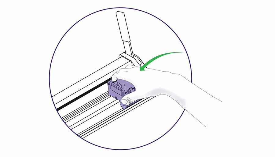
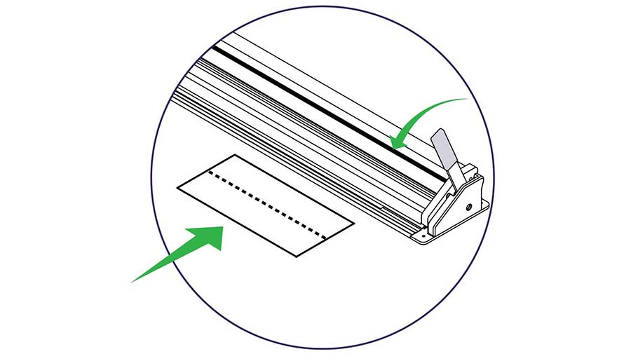
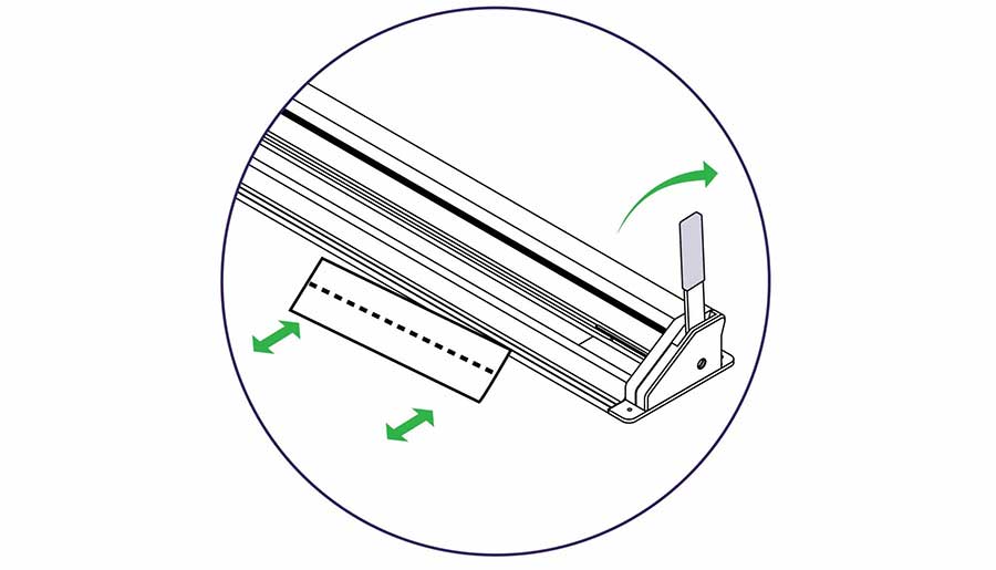
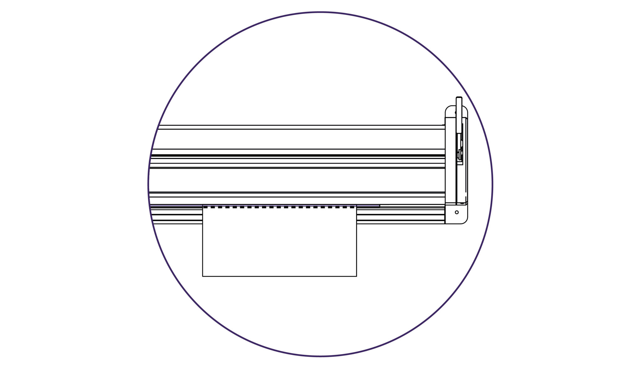
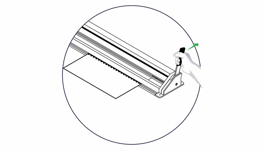
When fully aligned use the lever to lower the cutter bar onto the material and clamp it in position ready for cutting. Further cutting information is given in the sections under relevant tool heads.
See Double Graphik cutting techniques >
See the Fabric tool head cutting techniques >
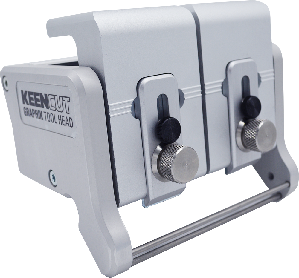
QuikSwap Graphik tool head for Evolution3 cutters, with two individual blade holders for two way cutting. Graphik blades are stronger and more stable than regular blades. Ideal for vinyl, banner, cardboard, PVC foamboard up to 13mm (½″), foam-centred board, corrugated plastic, paper, pop-up and roll-up materials.
This head is supplied as standard with all Evolution3 cutters.
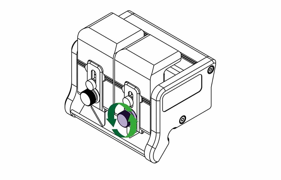
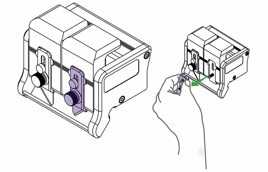
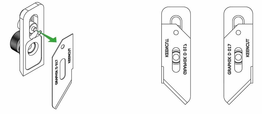
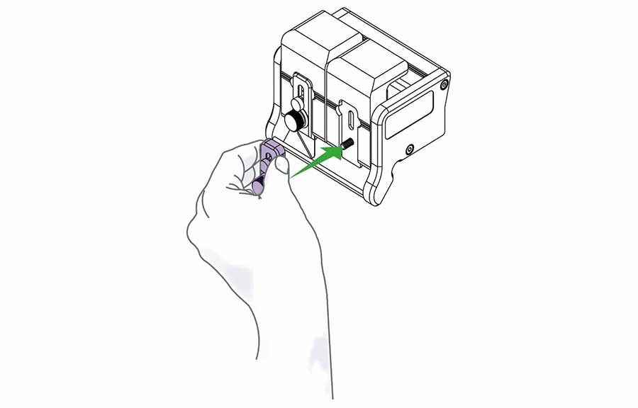
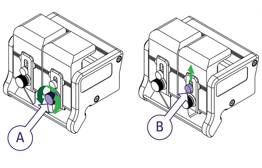
Replace the blade clamping plate onto the blade holder but do not tighten fully until the blade depth has been set (see how to adjust the blade depth >).
Repeat on the other blade holder if required.
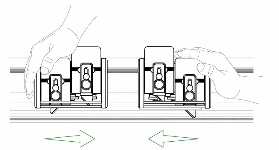
The cutting head can be pulled or pushed to cut the material. Load and align the material to be cut as described in the ‘clamping material’ section (see how to align and clamp the material >), press down the chosen blade holder whilst pushing/pulling the cutting head along the cutter bar.
Tip: Only finger pressure is needed to hold the blade holder down, if after making the cut the blade holder has risen and the blade not cut through simply cut again. This could be an indication the material should be cut in two strokes using the dual blade depth setting as explained above.
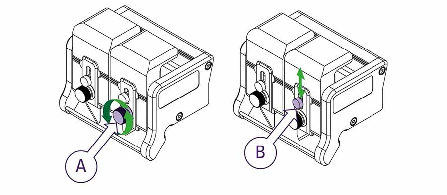
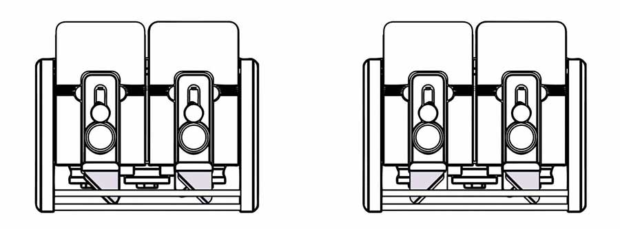
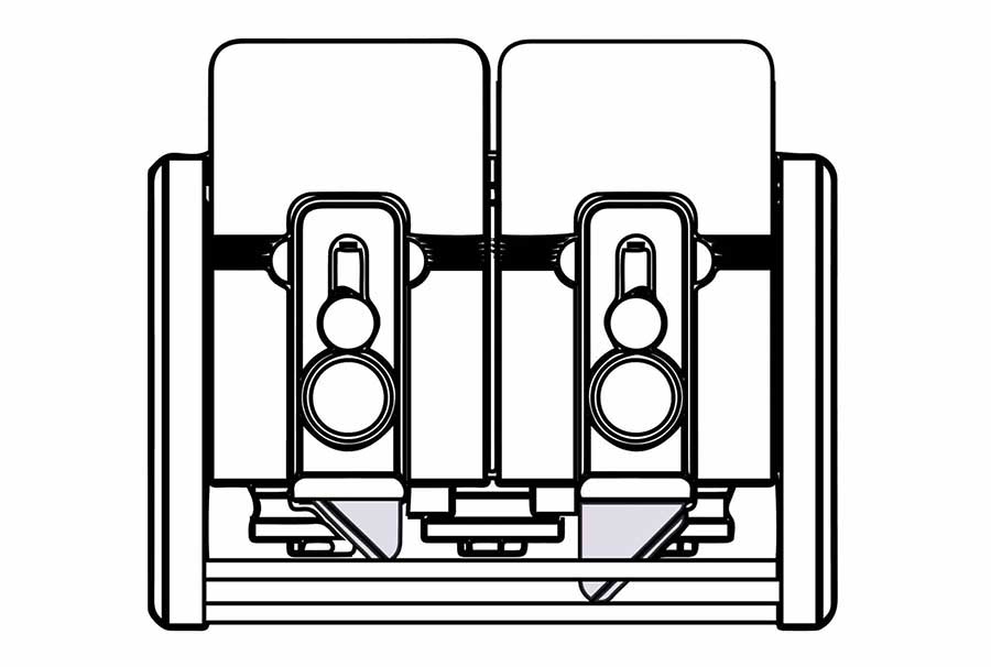
NOTE: The following is for a right-handed person.
For left-handed use cut at the left-hand end of the cutter and reverse the direction of cut and hand positions.
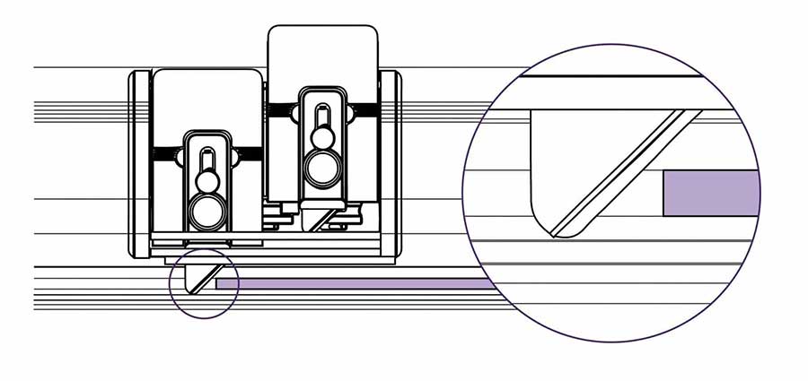
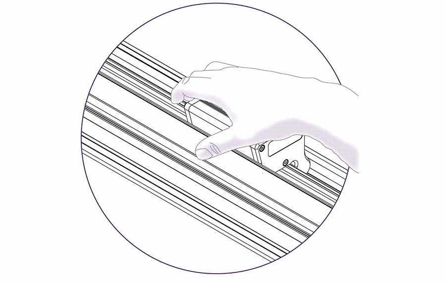
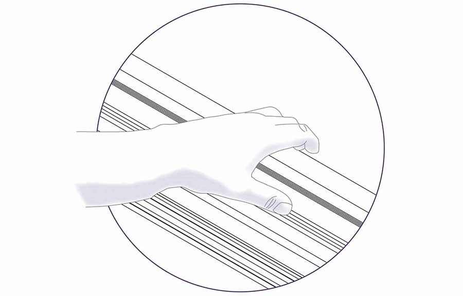
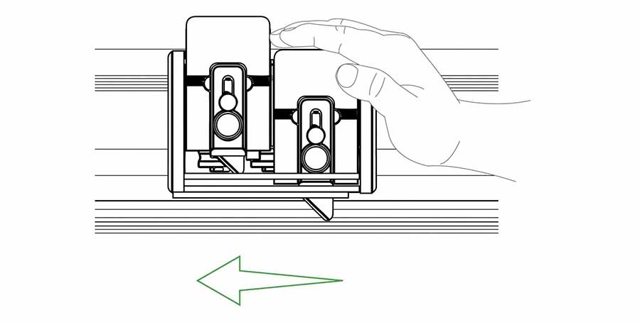
Cutting Aluminium Composite Panels is not recommended using the Graphik tool head.
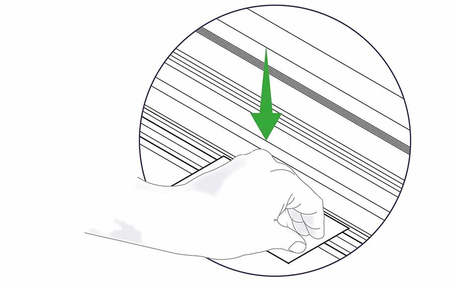
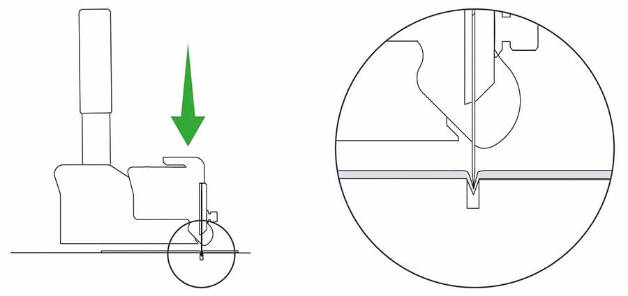
Check that the material is not being pushed into the cutting groove as the blade is cutting. If so, the material is likely to be suited to being cut with the rotary blade of the Fabric tool head where the underside of the material is supported on a cutting mat. As a short term measure, it is possible to use the Graphik blade on cutting mat. Refer to the Fabric tool head for instruction.
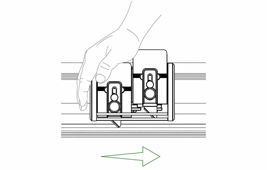
Scoring Acrylic and other plastics can be achieved by setting the blade at minimum depth and running the blade backwards across the surface whilst applying firm downward pressure on the blade holder.
Remove the material from the cutter for snapping by hand, some plastics may benefit from being scored multiple times.
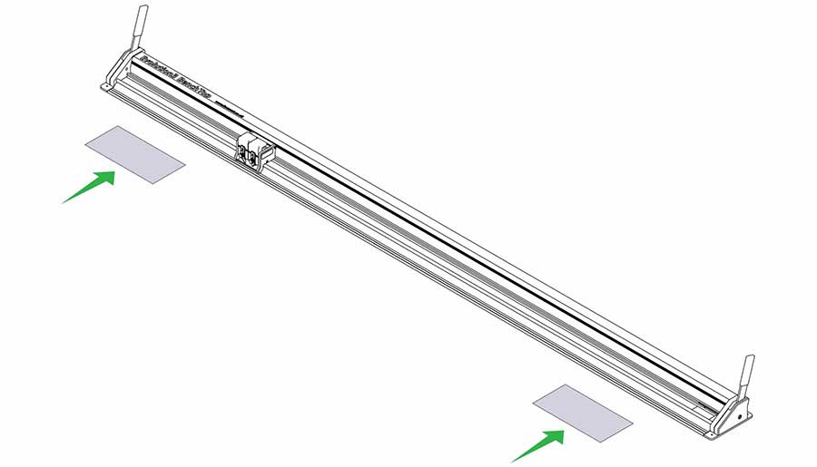
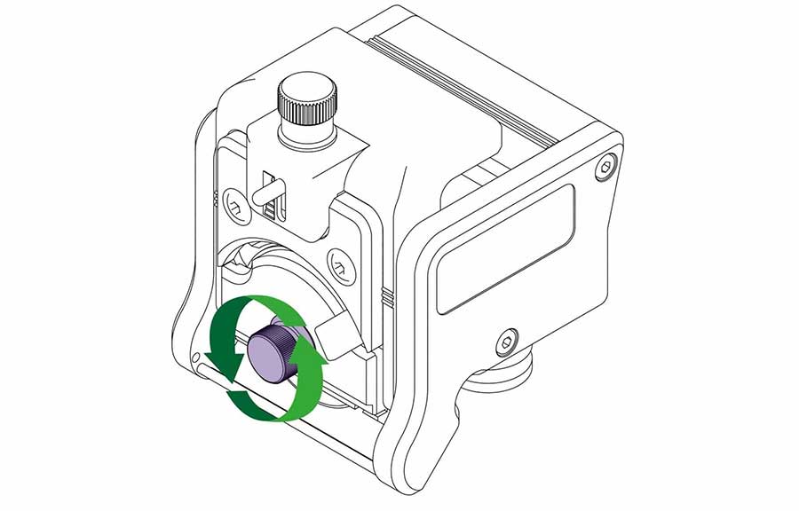
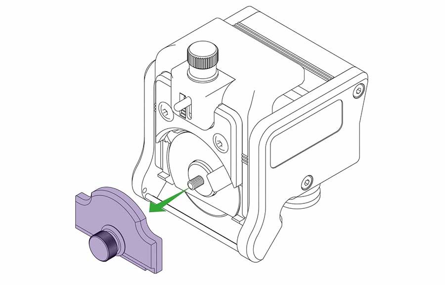
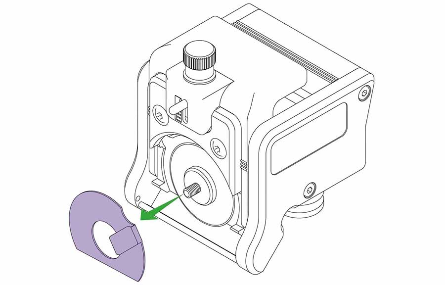
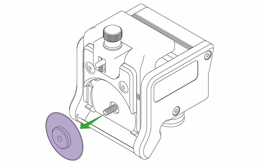
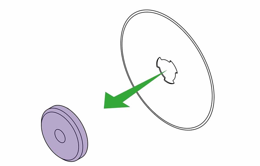
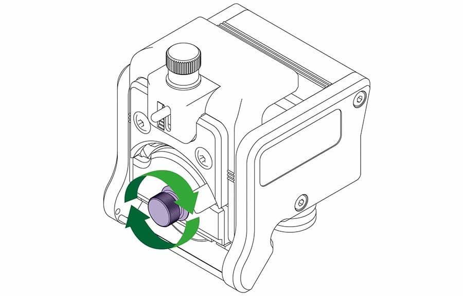
IMPORTANT: Before using the Fabric tool head, you must use a cutting mat.
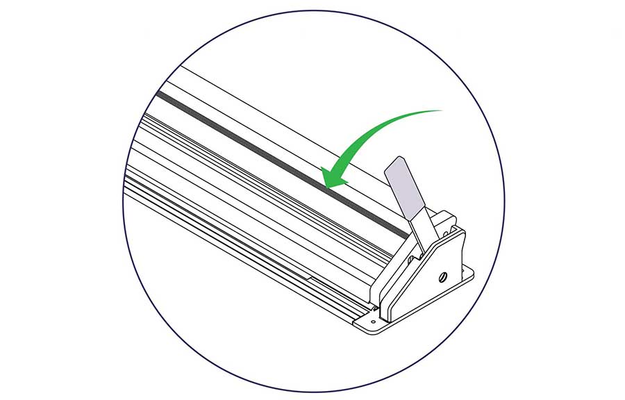
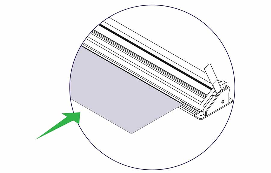
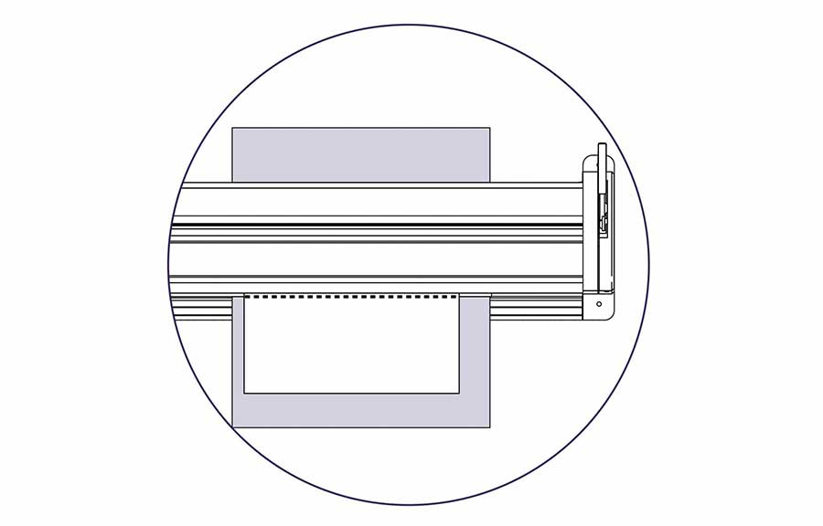
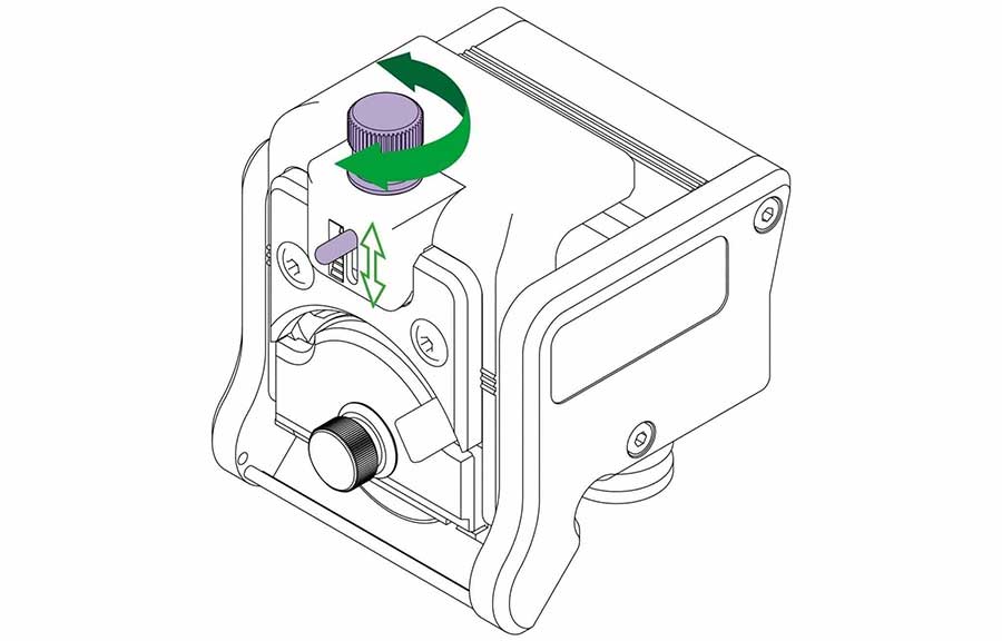
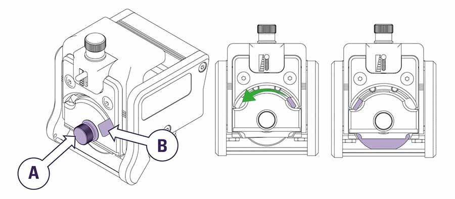
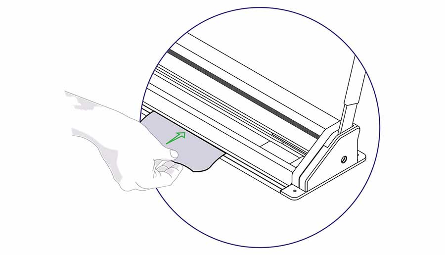
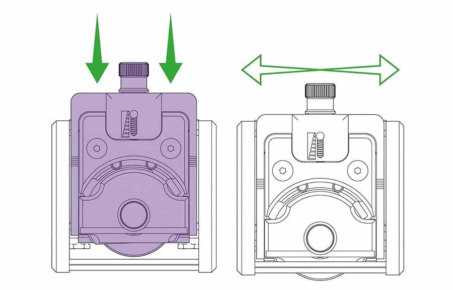
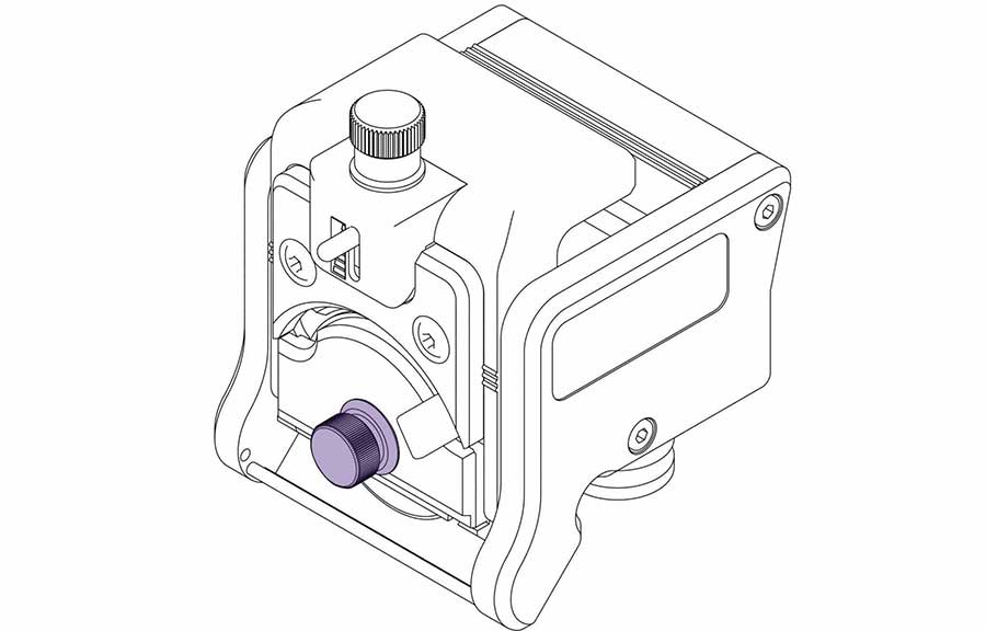
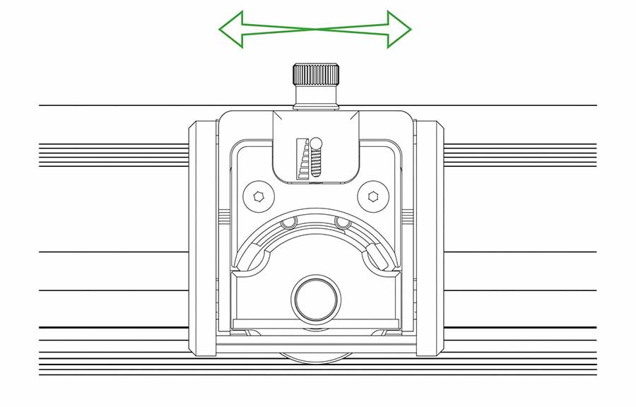
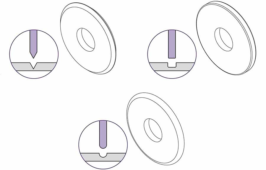
NOTE: The Fabric tool head can also be used to cut many other thin materials such as paper and film.
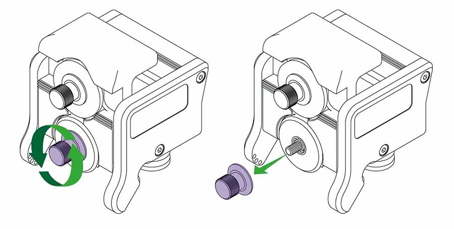
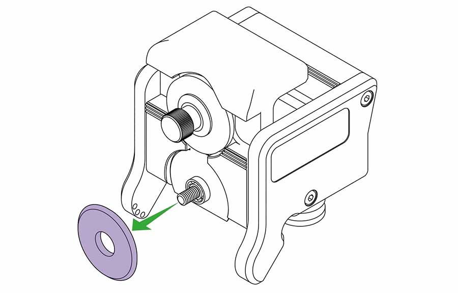
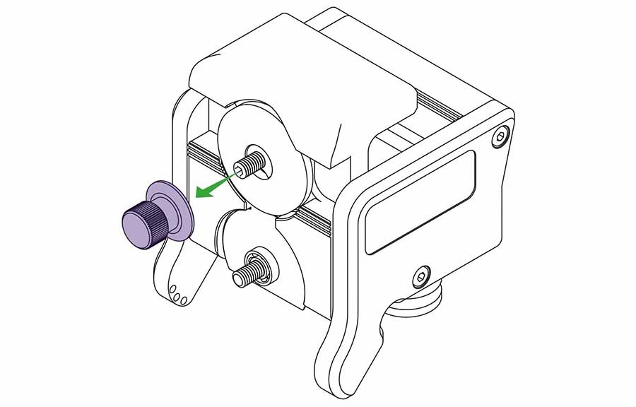
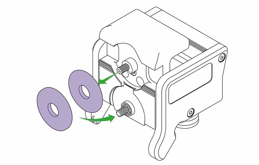
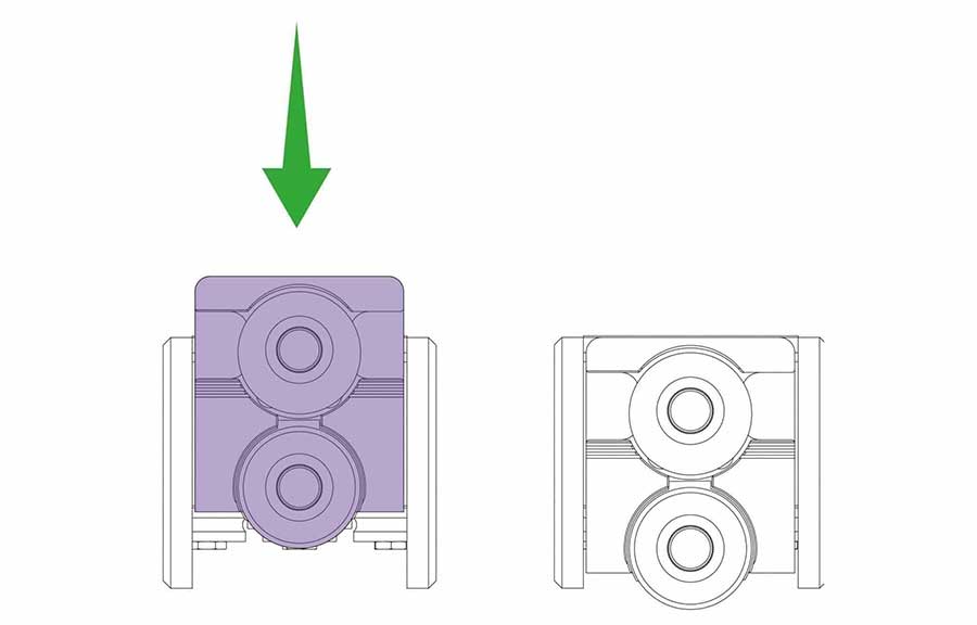
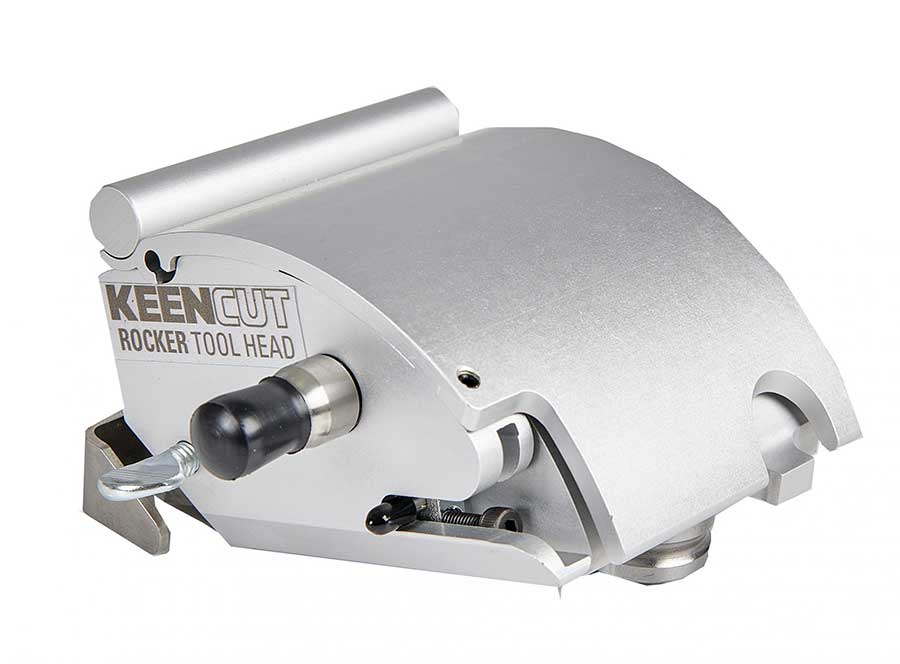
The Rocker tool head has been especially designed to give perfect comfort for all day, every day, cutting. The tool head fits the curve of your hand, allowing you to cut denser materials with ease.
The Rocker head accepts the Medium Duty blade and the specialist Tech D012 blade. This will allow you cut Aluminium Composite Panels (ACP) alongside standard materials.
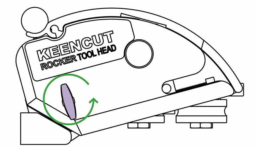
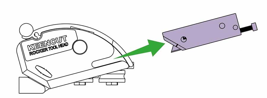
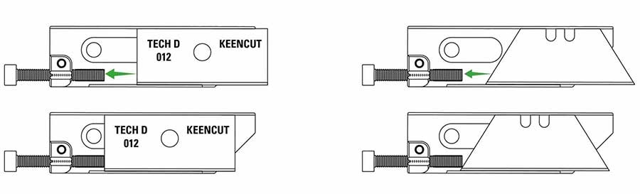
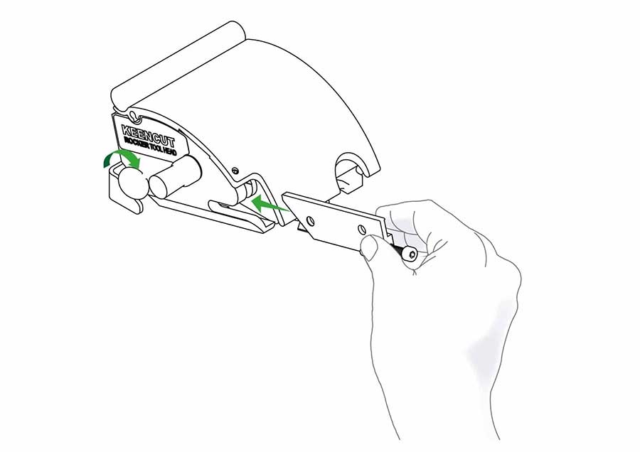
Aluminium Composite Panels can be cut using the Rocker tool head. The following method is only intended for occasional use, for cutting on a regular basis the SteelTrak should be considered.
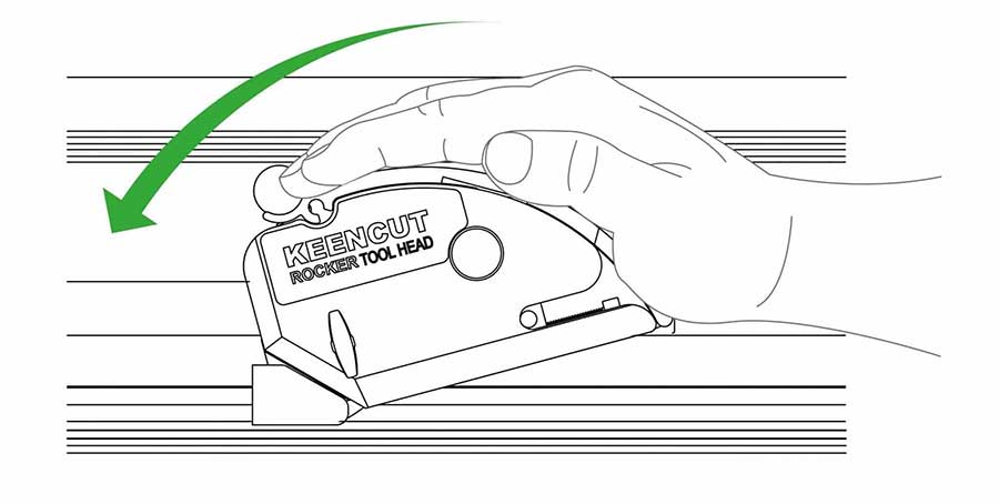
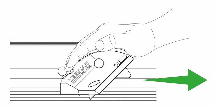
With the blade engaged, pull the Rocker tool head in one continuous motion along the material to achieve the best results.
If the material creases at the beginning of the cut use the index finger on your other hand to pinch the material onto the base plate and hold it in place whilst the blade enters the material.
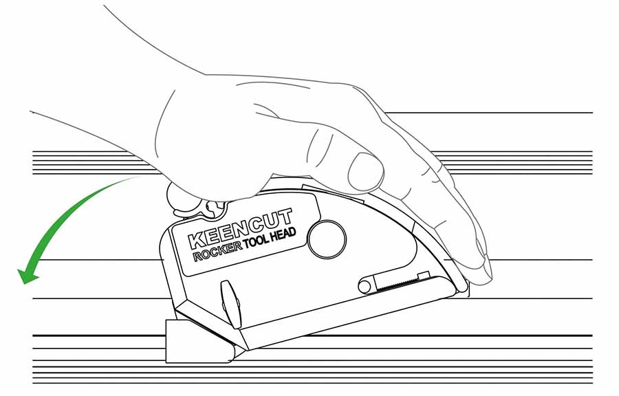
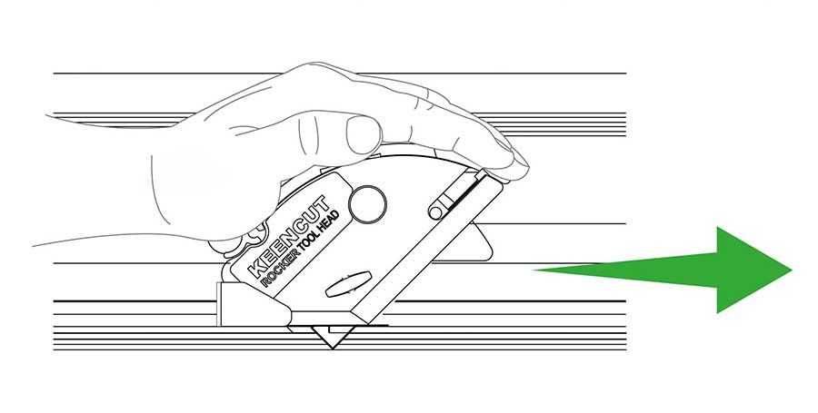
Aluminium Composite Panels can be cut using the Rocker tool head. The following method is only intended for occasional use, for cutting on a regular basis the SteelTrak should be considered.
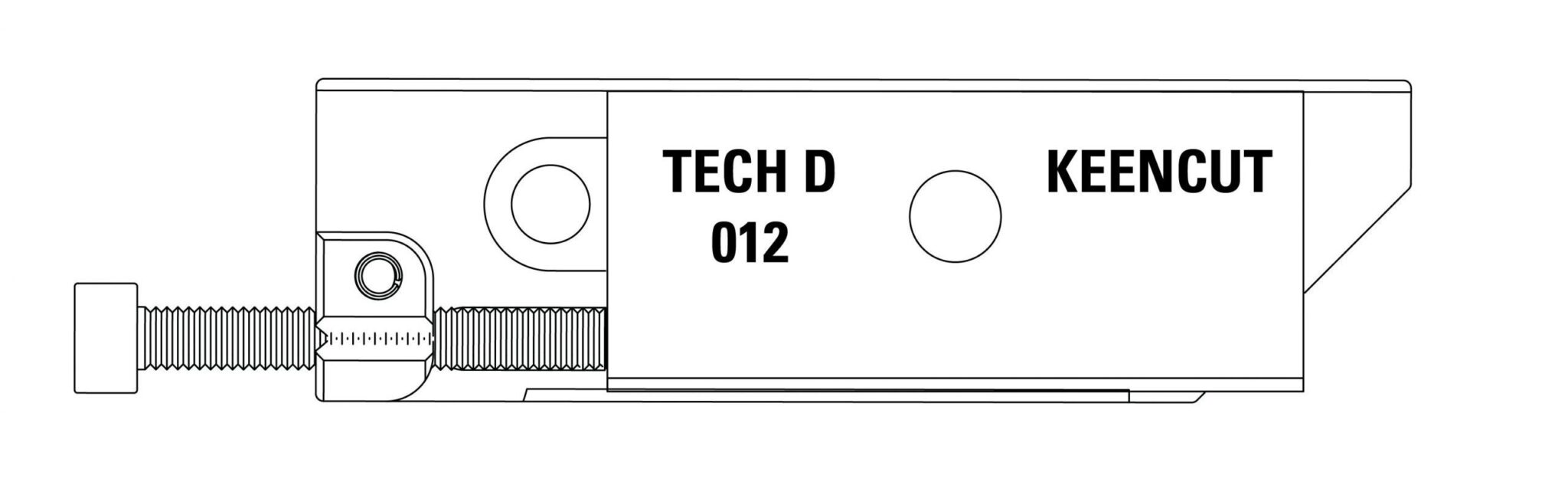
Alternatively, some ACP’s will snap once the top foil has been cut, bend back and forth a few times to break the bottom foil then clean the edges with a file.
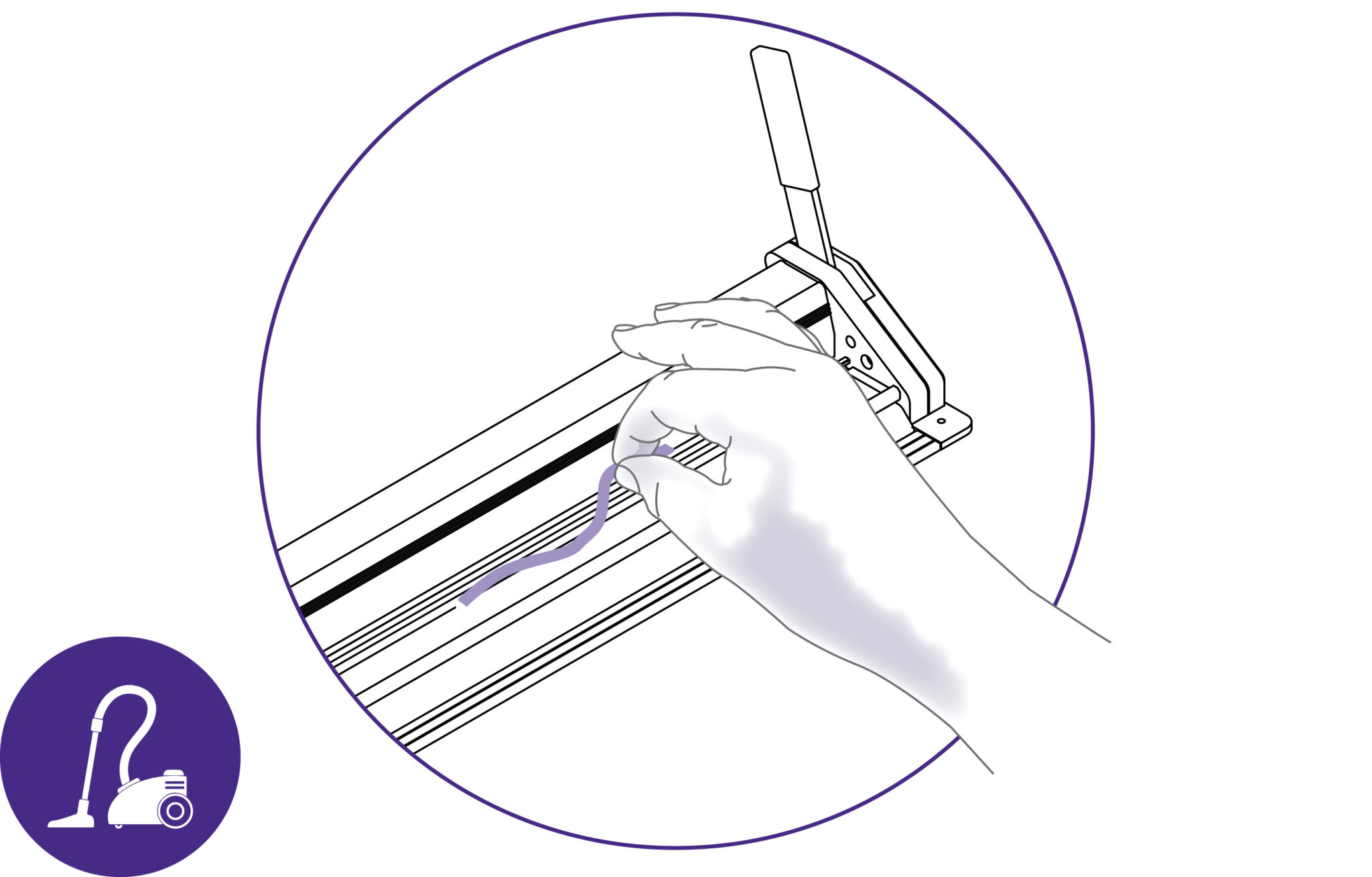
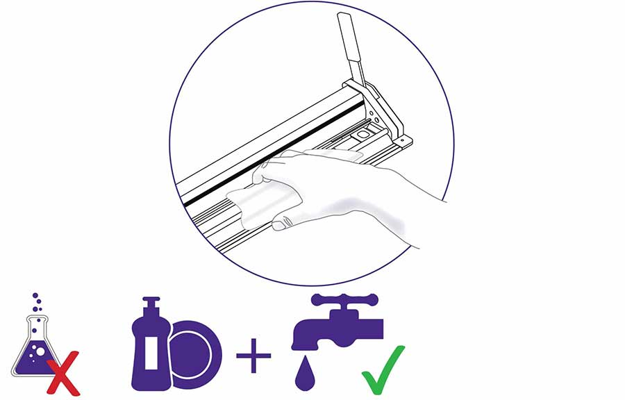
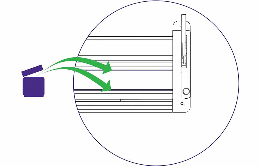
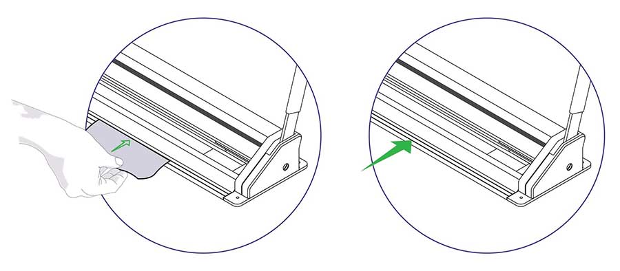
IMPORTANT: Ensure that you have a replacement sightline strip before proceeding
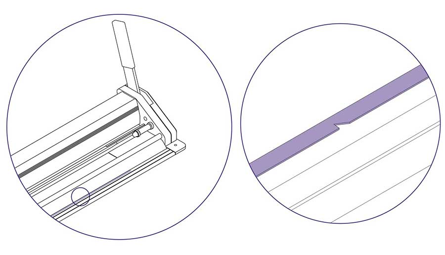
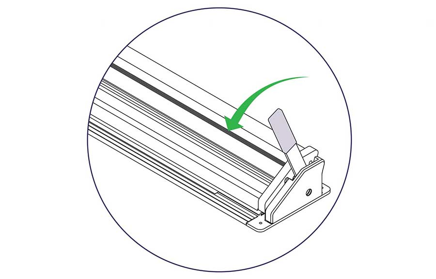
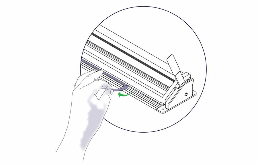
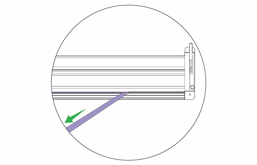
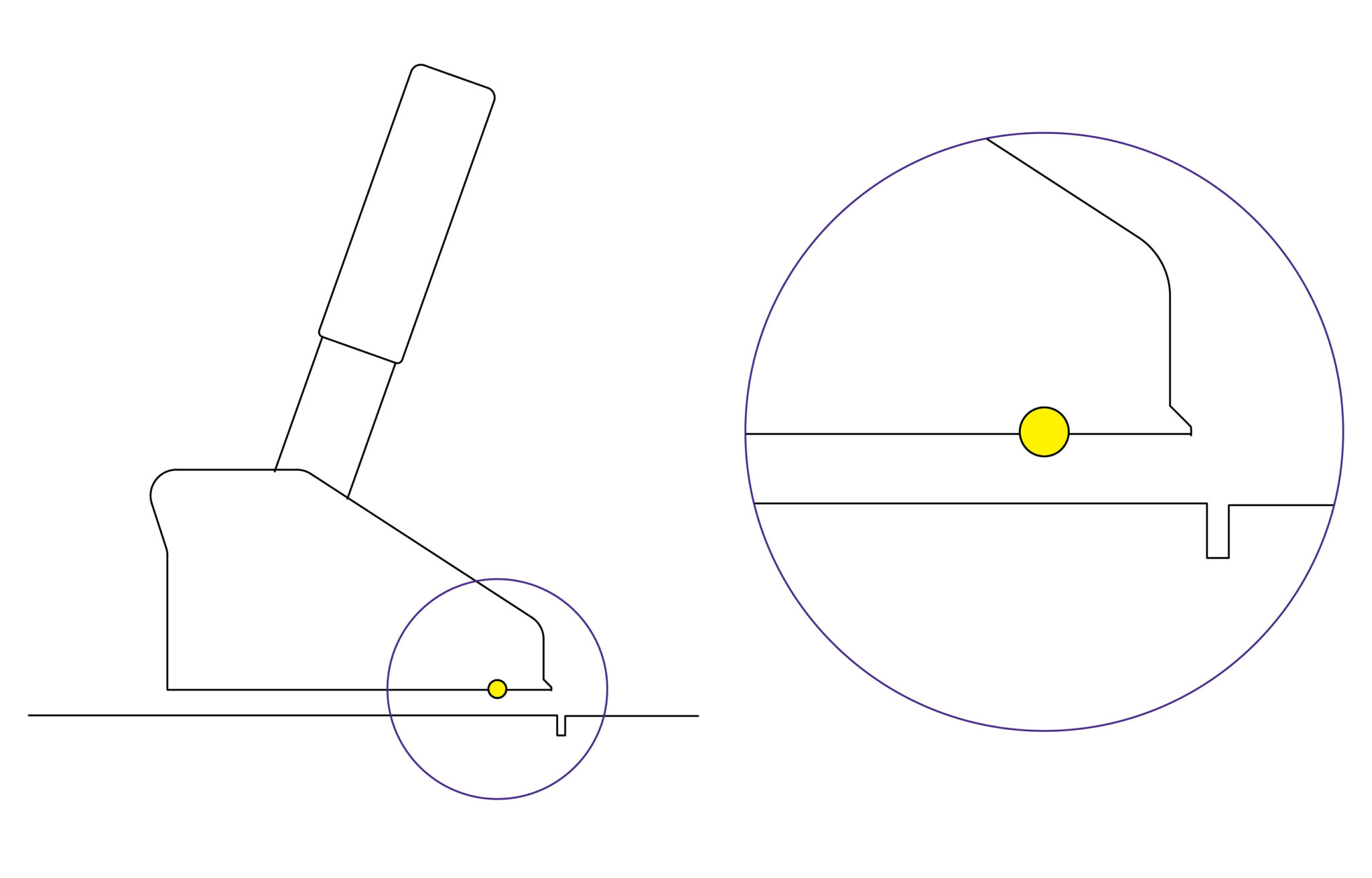
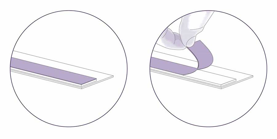
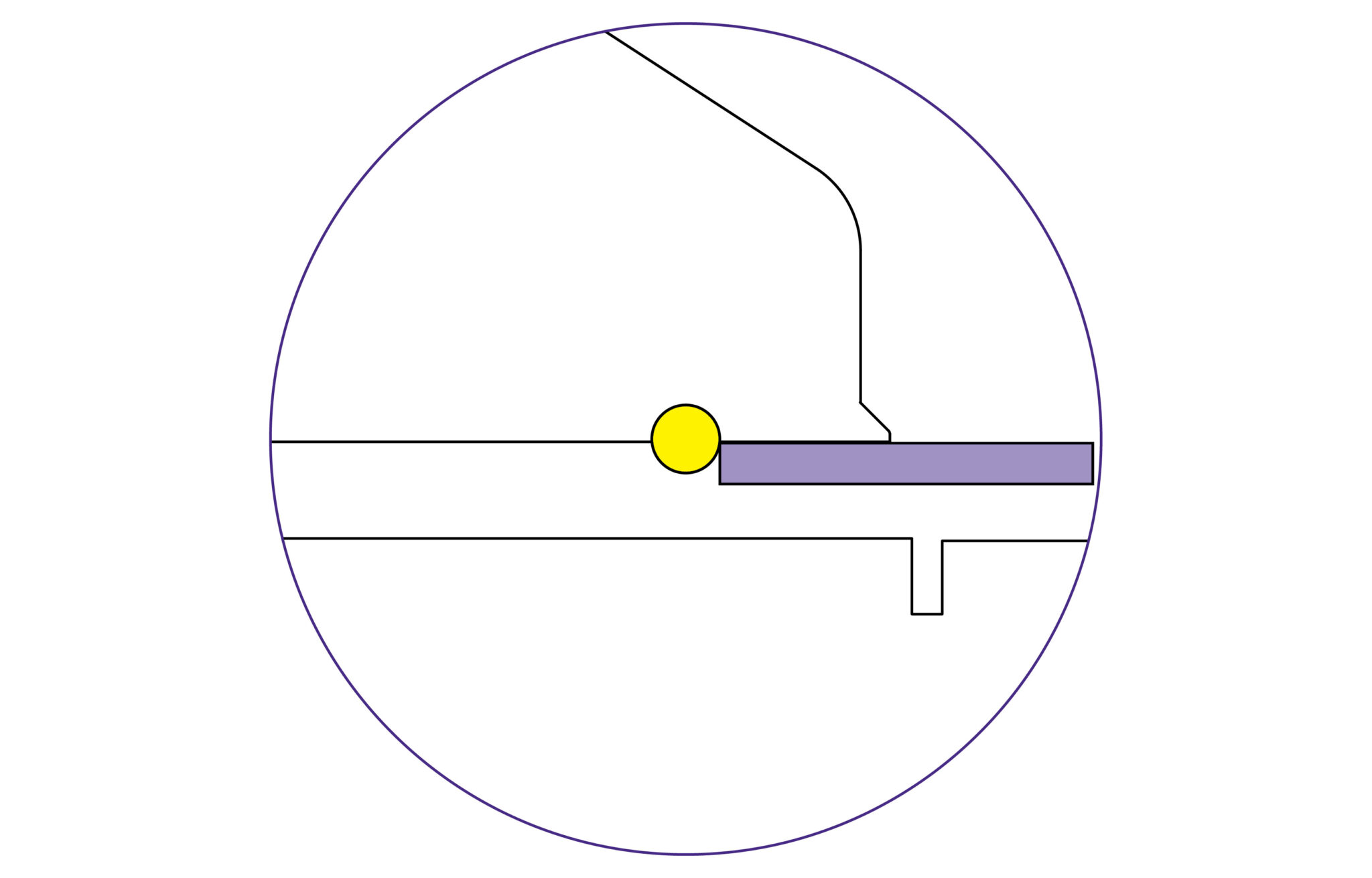
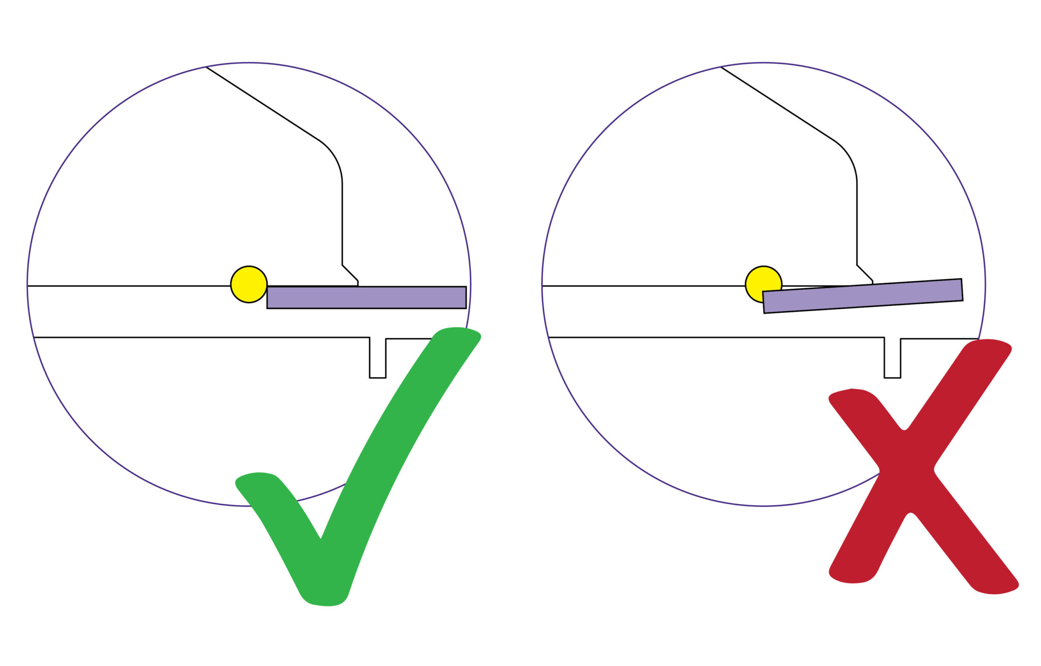
Apply the sightline strip in stages from one end of the cutter bar to the other using the yellow silicone chord as your guide; the back edge of the sightline strip should be touching the front edge of the silicone chord.
TIP: Remove the protective backing from the double sided tape in stages to prevent complications during application.
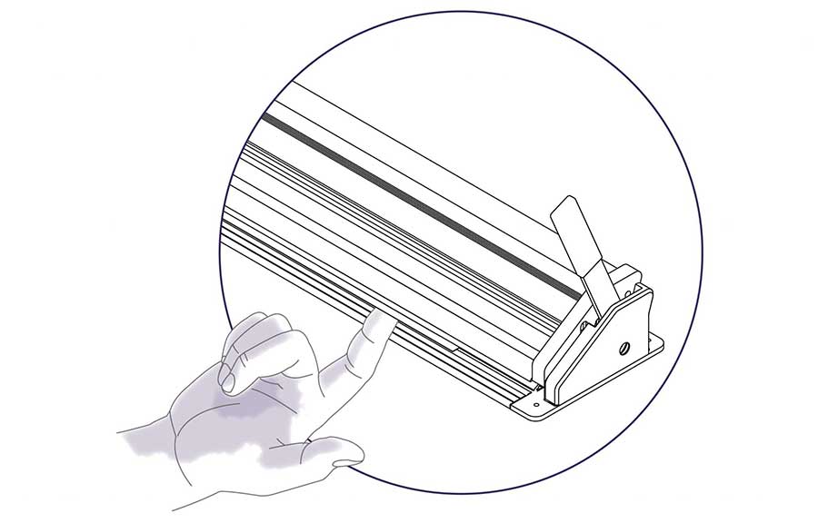
IMPORTANT: When trimming the sightline strip it must be done on a piece of scrap material or cutting mat as the sightline strip can deflect into the groove.
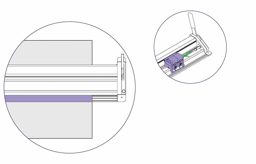
The sightline strip is wider than it needs to be and requires trimming to suit cutting line of the machine.
Use the Double Graphik tool head to gently cut through the sightline strip in 3 to 4 passes. This will ensure the sightline strip is not distorted and indicates the blades line of cut accurately.
TIP: Order replacement strips (or check stock) whenever you change the strip to save running out.
This User Guide for the Evolution3 BenchTop gives advice on cutting techniques, using the different cutting heads and care and maintenance of your machine.
Before using your machine make sure that you have installed and calibrated it correctly. Full details are in the Installation Manual.

Ⓒ Keencut 2026 | Baird Rd, Corby NN17 5ZA United Kingdom | Contact us
Created by DeType | Privacy | Website Disclaimer | Terms & Conditions


