
How to replace the ratchet lever and the ratchet plate on the Excalibur
To do this you will need the Excalibur 3S & Excalibur 5000 ratchet service kit >
Tools required.
- Allen (hex) keys 2.5 & 5mm
- 8mm spanner/wrench
- 10mm spanner/wrench
- Petroleum jelly (Vaseline) or lithium grease.
- Silicone lubricant
- Parts diagram – page 4
What to do
Remove the cutting head from the machine:
- Raise the multi-cutter head above the level of the squaring arm and fasten it in place with the white plastic knob on its right-hand side.
- Locate the black plastic cover strip that runs down the right-hand side of the cutter bar, remove it by pulling it out to the right at the bottom end.
- At the bottom of the cutter bar under the strip are two Allen (hex) screws, use a 5mm Allen (hex) key to remove the smaller one and then the plate covering the bottom end of the cutter bar can be removed.
- Remove the cylindrical black plastic buffer from the left-hand side of the cutter bar.
- Slide the cutting head of the end of the cutter bar.
Remove the swinging arm casting.
NOTE: There are many different washers and nuts that must be reassembled in the same order and orientation please take notes or photographs at every stage to be able to refer back to.
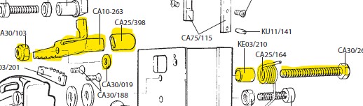
- Remove the black plastic guard by loosening the knob and using a 10mm spanner/wrench to remove the securing nut and washers.
- Remove the cutting head return spring by unlatching the outer leg of the spring from its groove on the swinging arm casting.
- Rotate the spring coil on its plastic mandrel until the other shorter leg of the spring comes free.
- Pull the coil free from its mandrel.
- Remove the nut and washers adjacent to the curved slot in the casting using an 8mm spanner/wrench

- Remove the lower casting fixing nut and washer (note the washer’s orientation) with a 10mm spanner/wrench.
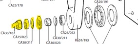
- Remove the swinging arm casting being careful the two large washers and thrust bearing behind its lower end do not fall away. Remove the plastic and steel washers from the top fixing screw.
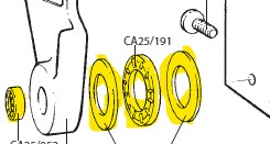
- Replace the ratchet plate on the back of the casting using a 2.5mm Allen (hex) key
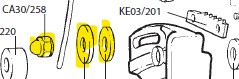
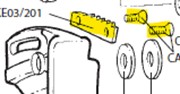
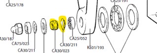
- Remove the ratchet lever nut using an 8mm spanner/wrench and take off the ratchet lever and washer. Remove the long screw, spring and spacer from the back face of the carriage after first taking a photograph of the spring position for reference.
- Insert the replacement long screw first passing it through the spacer and spring, it is important the bent leg of the spring is under the head of the screw. Ensure the screw is tightened using the 8mm spanner/wrench.
- Lubricate each side of the ratchet lever adjacent to the pivot hole with a small amount of petroleum jelly or lithium grease.
- Fit the replacement washer and ratchet lever, push the leg down through the square hole and fit the locking nut with the 8mm spanner/wrench, bring the nut into contact with the ratchet lever but do not tighten.
- From the back of the carriage rotate the bent leg of the spring clockwise so the other short leg meets the edge of the ratchet lever, continue to rotate and tuck behind the head of the adjacent stop screw (refer to your earlier photograph if taken)
- Adjust the locking nut so that any further clockwise movement prevents the lever being rotated by the spring.
- Clean and smear with petroleum jelly or lithium grease the two large washers and thrust bearing from the bottom end of the casting. Check and lubricate the small bearing.
- Replace the steel washer on the top screw then the plastic washer and apply silicon lubricant.
- Replace the swinging arm casting over the two screws, press down on the ratchet lever to mesh the teeth. Replace the dish shaped washer with the orientation as before then replace and lightly tighten the nut with a 10mm spanner/wrench.
- Apply silicon lubricant to the face of the castings curved slot, place a plastic washer over the top screw followed by the steel washer then the dome shaped nut. Tighten the nut enough to prevent sideways movement of the casting but to allow it to move back and forth.
- Replace the plastic guard and its associated washers and fixing nut but leave it in its open position, tighten the nut only enough to remove any loose movement but still allow it to open and close.
- Insert the short leg of the swinging arm return spring into the gap between the casting and the carriage and feed the coil onto its plastic mandrel so that the long leg of the spring is pointing vertically up
- Rotate the leg clockwise when viewed from the left and latch it under the groove in the casting on the edge of the raised circular upstand.
Important:
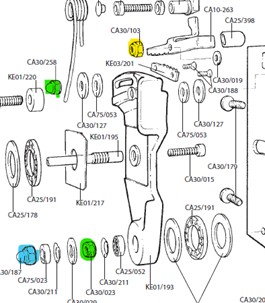
- Check the adjustment on the yellow nut, the ratchet lever should move freely but not from side to side and return under its spring pressure.
- Check adjustment on both green nuts such that the swinging arm casting engages easily, returns fully when the ratchet lever is disengaged and there is no sideways movement.
- Check the blue nut allows the guard to move but not such that it is loose.
- Recheck all the nuts after a few weeks of use.
Ⓒ Keencut 2020 | Baird Rd, Corby NN17 5ZA United Kingdom | Contact us
Created by DeType | Privacy | Website Disclaimer | Terms & Conditions