
Excalibur 6000 user guide – Maintenance
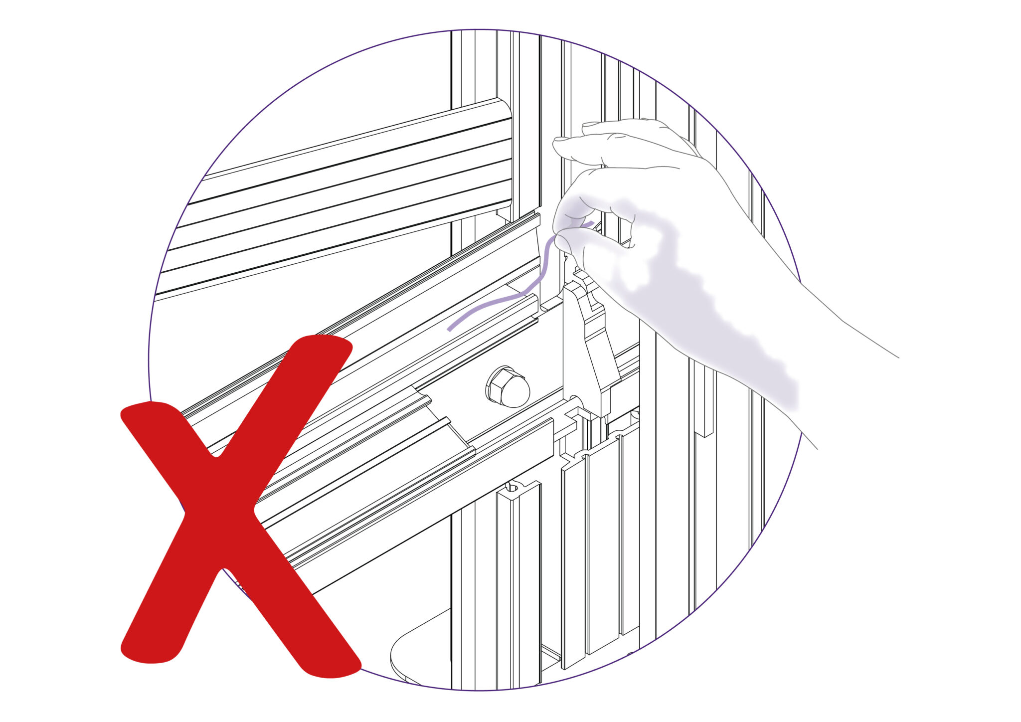
Do not wipe the Squaring Arm channels or remove any debris with fingers, as it may contain sharp particles such as glass.
Use a vacuum cleaner if possible. If a soft brush is used, work slowly and do not allow particles to flick off the bristles.
Guide rods and rollers:
Wipe using cleaning solvent on a cloth, and lubricate the surfaces very lightly with petroleum jelly. The axles of the rollers are lubricated and sealed for life and need no further attention.
Lubrication frequency: After 2 weeks of use and then every month thereafter (except on axles of rollers).
Ratchet system:
Use a light oil (3 in 1), one or two drops on the pivot point and one drop on the ratchet teeth.
Lubrication frequency: After 2 weeks of use and then every month thereafter.
Balance weight:
Silicon Lubricant sprayed in from the top of the balance weight opening whilst the Twin Wheel Cutting Head is parked at the top of the machine.
Lubrication frequency: After 2 weeks of use and then every month thereafter.
Ratchet release bar:
Smear edge with petroleum jelly.
Lubrication frequency: After 2 weeks of use and then every month thereafter.
Swinging Arm:
Petroleum jelly around curved slot.
Lubrication frequency: After 2 weeks of use and then every month thereafter.
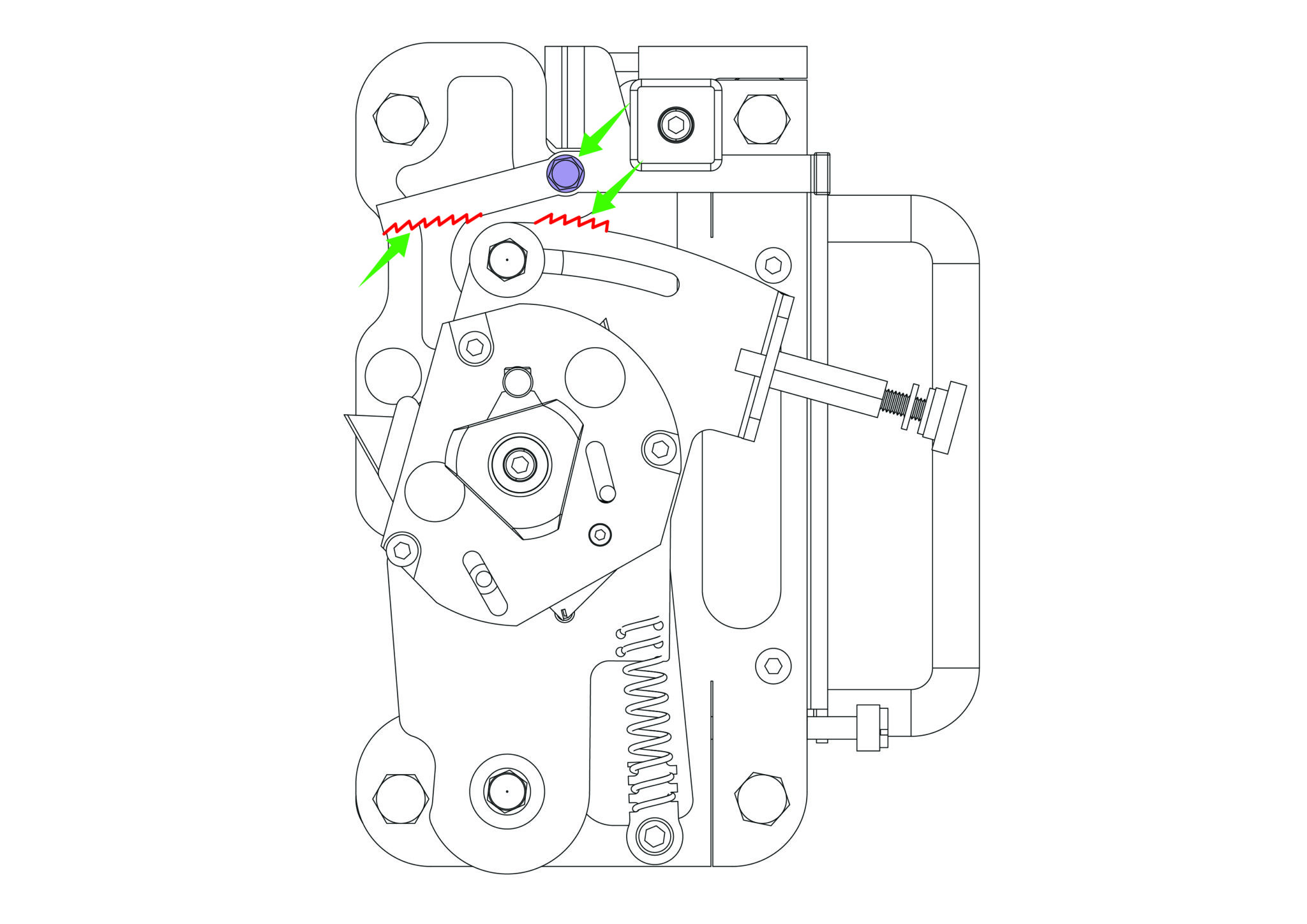
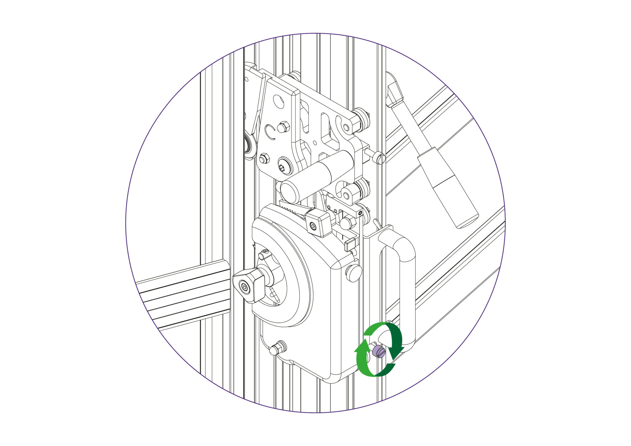
The pressure of the clamp is in relation to the amount of pressure applied to the operating handle, however in time the maximum clamping pressure can reduce due to wear on the friction block (hidden within the machine).
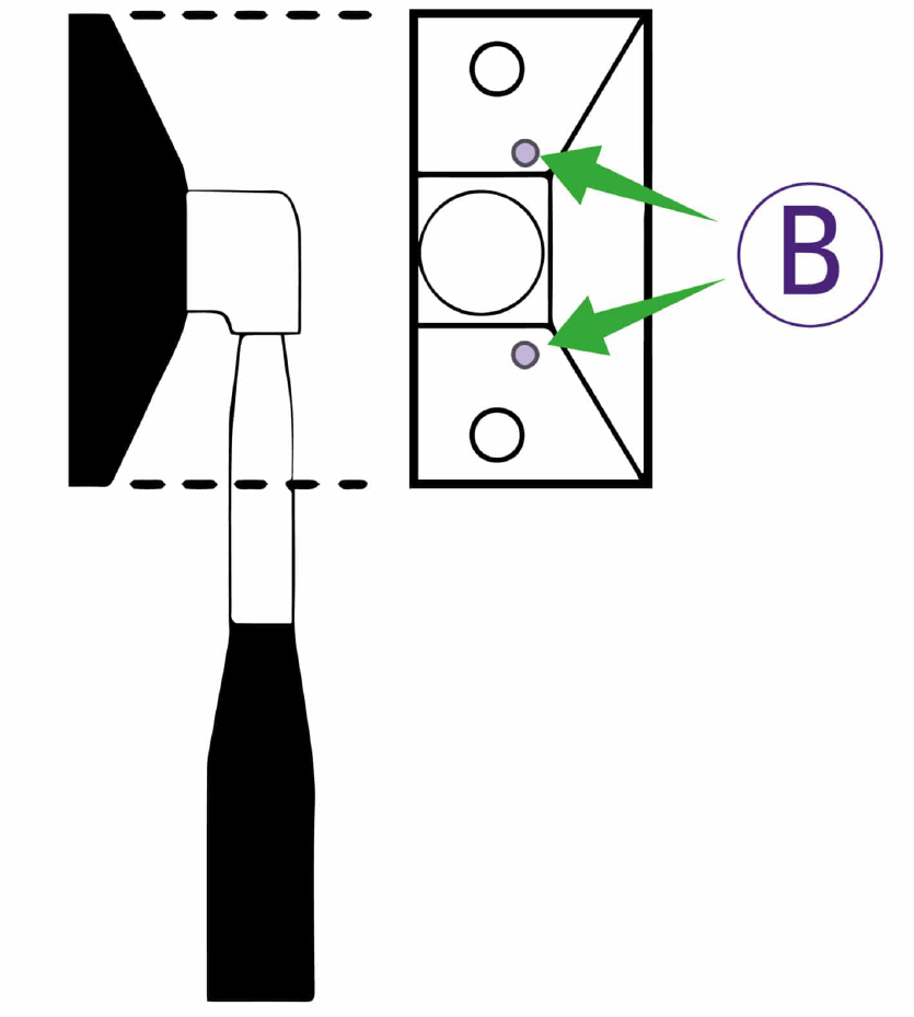
Compensation for this can be made by adjusting the two small grub screws (labelled B) in the operating handle housing as shown. Turning the screws lightly clockwise until they stop moving and then undoing them by quarter of a turn should provide an acceptable pressure, but further small adjustments can be made to increase or decrease the pressure as required.
When cutting tough materials it is essential that the clamping system operates at its’ optimum, the moving clamp bar must press evenly onto the board being cut and not clamp it only at the top or bottom.
To check for parallel clamping, use 2 pieces of A4 paper, place one under the bottom end of the clamp and hold the other at the top end whilst depressing the clamp handle. Then check that the clamp firmly grips the pieces of paper. If it does not clamp both pieces firmly, follow the steps below.
Open the clamp by at least 1-2mm and remove the plastic cover strip situated above the clamp handle it just clips out of place, use the end of a small steel rule to lever it from its’ groove.
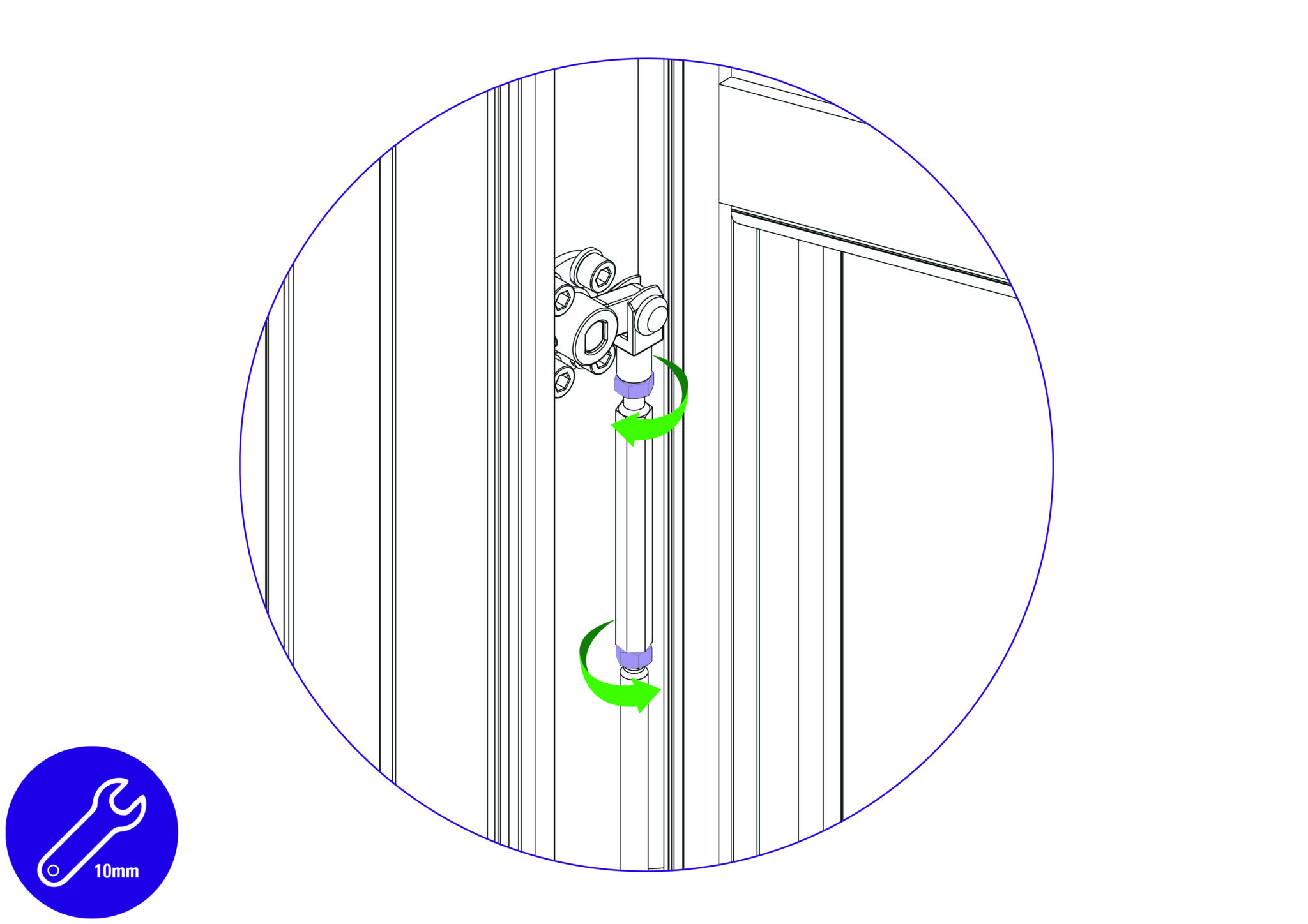
The clamp adjuster is at the top end of the push rod and is locked in position by two locking nuts.
The top nut has a normal right-handed thread, slacken it using a 10mm wrench by turning it counter clockwise when looking from below.
Now slacken the bottom nut, which has a left hand thread and should be turned clockwise when viewed from below.
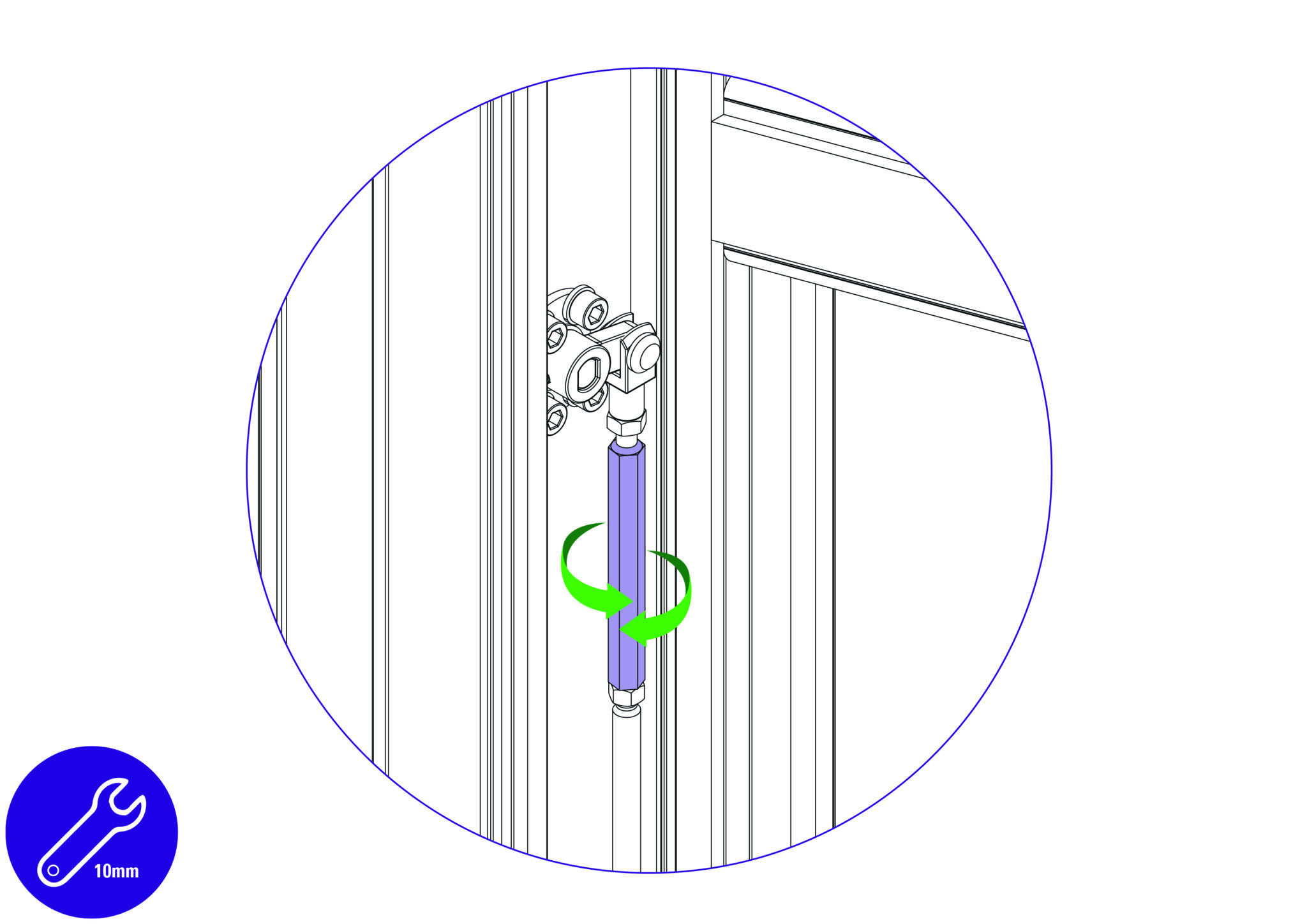
The ‘adjuster’ is the hexagonal bar between the two nuts, and by turning it with the spanner it alters the clamps alignment with the back of the machine.
Rotate the adjuster whilst observing the clamp from the side and bring the clamp into parallel.
Repeat the initial check using the 2 pieces of A4 paper, to ensure the clamp has been brought into parallel.
Once parallel is confirmed, tighten the two locking nuts whilst holding the adjuster in position with the second spanner. Then operate the clamp a few times and check/adjust further if necessary.
Finally, replace the plastic cover strip.
The Blue Support Boards on the Main Body and Support Arms offer an element of protection to materials being cut, in particular coated glass surfaces. Over the machine’s lifetime it could be expected that these Blue Support Boards could experience wear and may need replacing.
Removing from the support arm:
Slightly remove the edge of the Blue Support Board using a thin and rigid item such as a ruler. Peel the layers of double sided tape from the support arm if any tape remains on the surfaces. Clean the surface of the support arm with white spirit to clear any remnants of adhesive.
Ensure the surface is clean and dry before fitting the new Blue Support Boards onto the Support Arms.

Placing onto the support arms:
Peel the release paper from the adhesive face and align the angled face of the board with the angled face of the Support Arm that does not have the end cap attached. Ensure that the board in central to the Support Arm and that it does not overlap on to the Main Body face.
Proceed to lower the Blue Support Board onto the Support Arm surface, starting from the aligned edge.
Remove the protective film.
Removing from the main body:
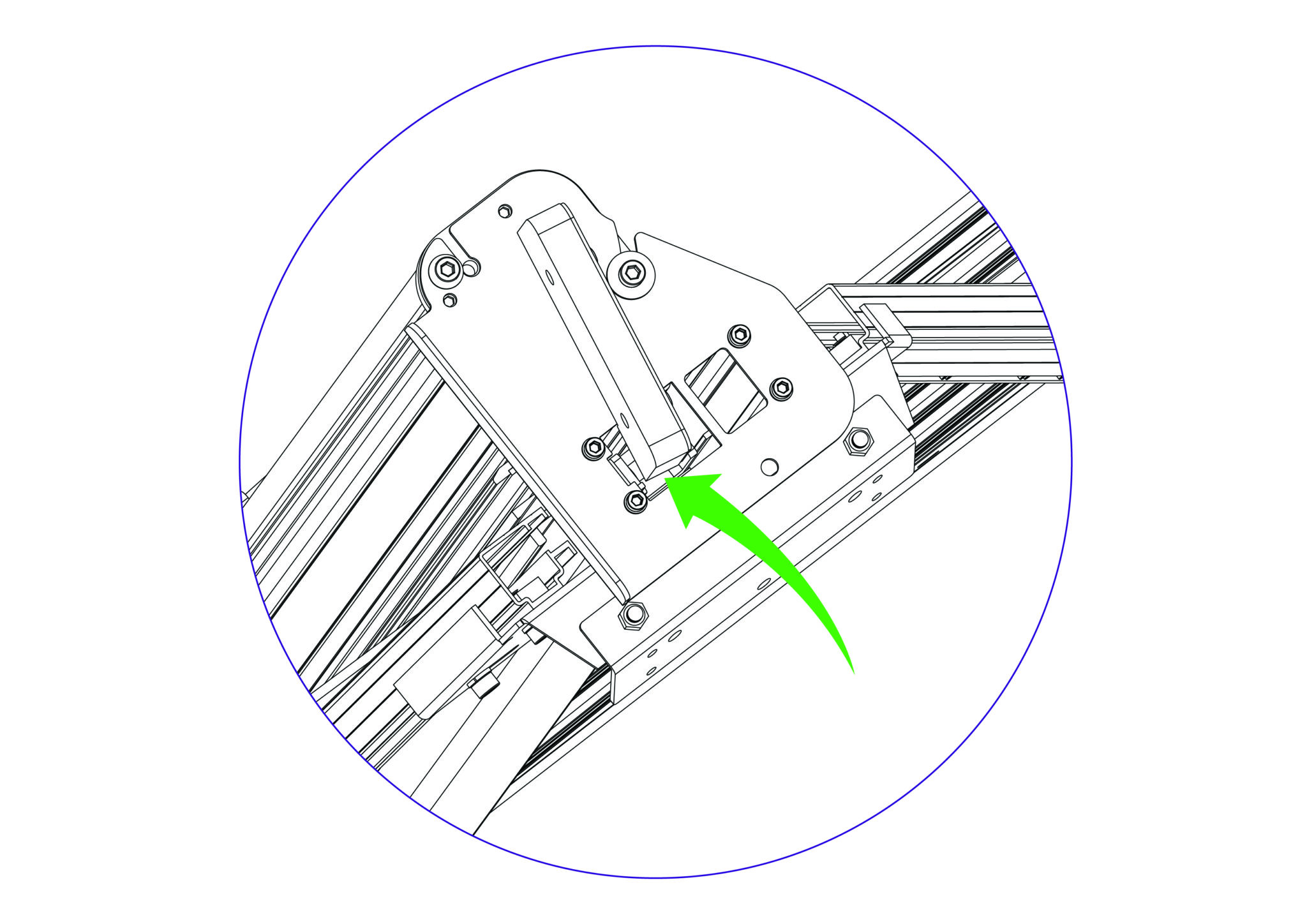
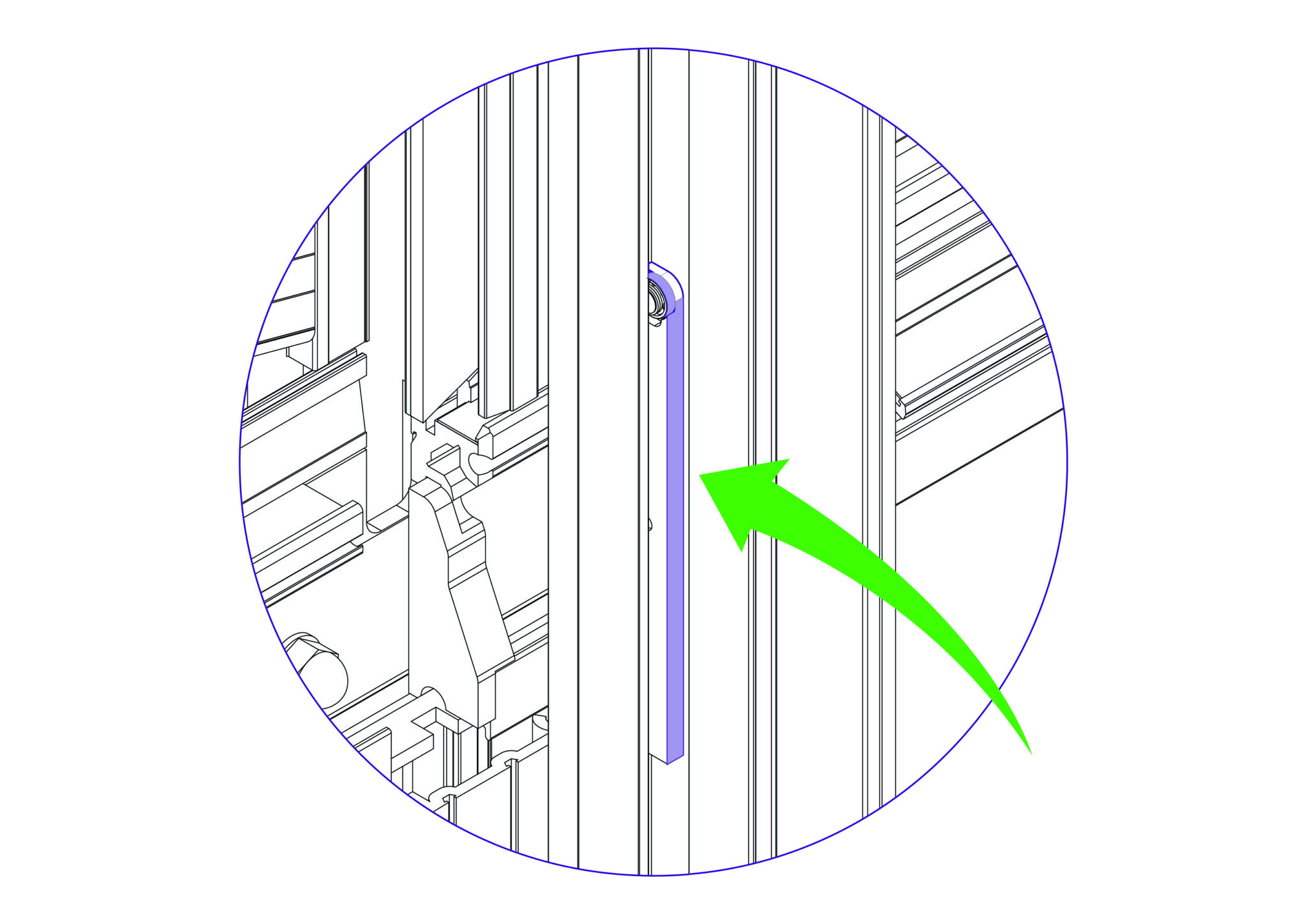
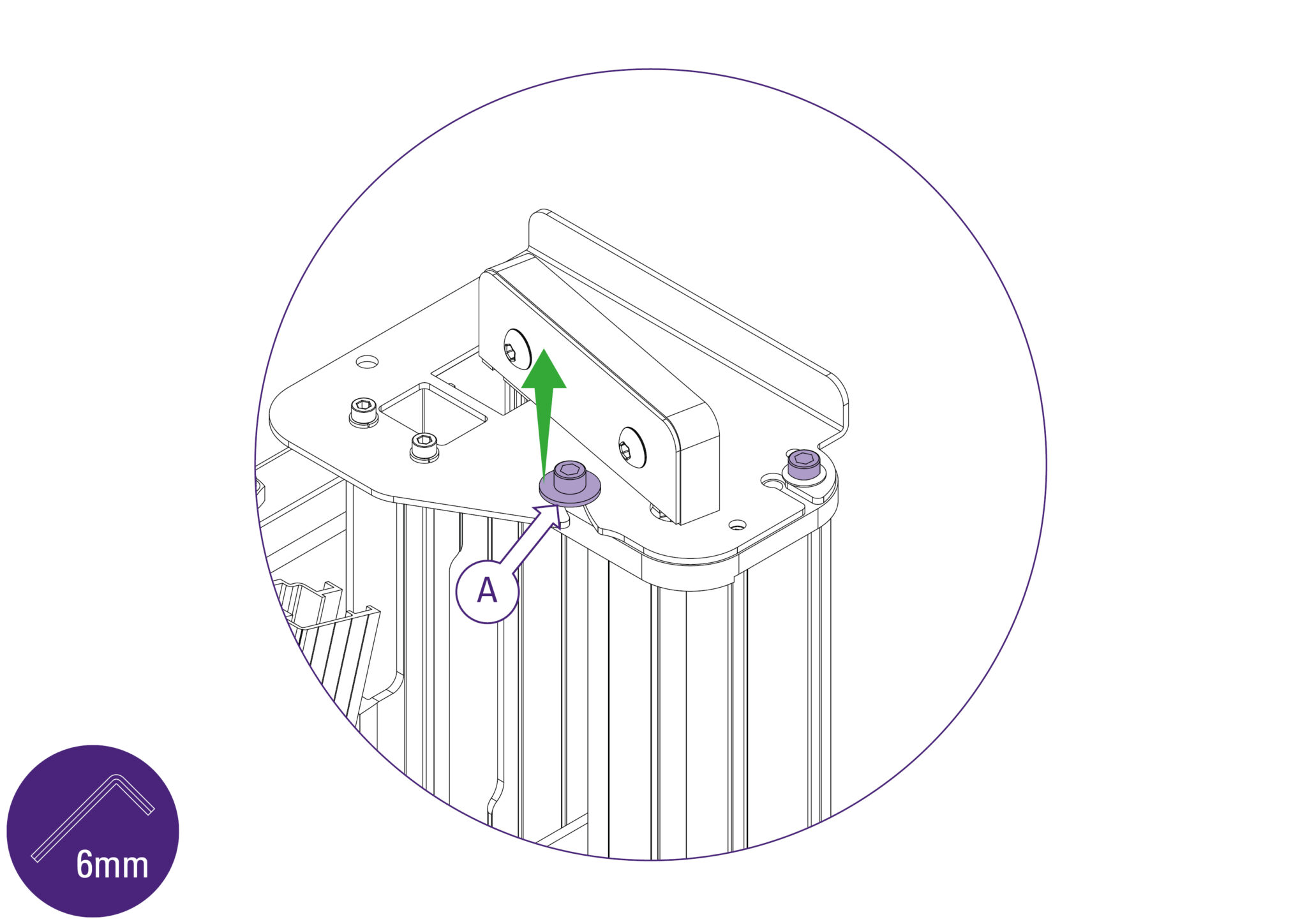
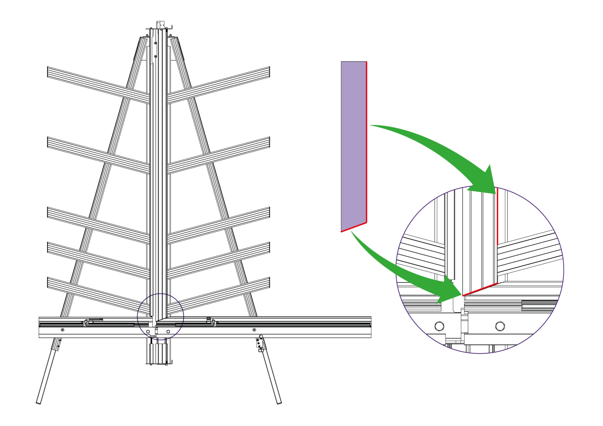
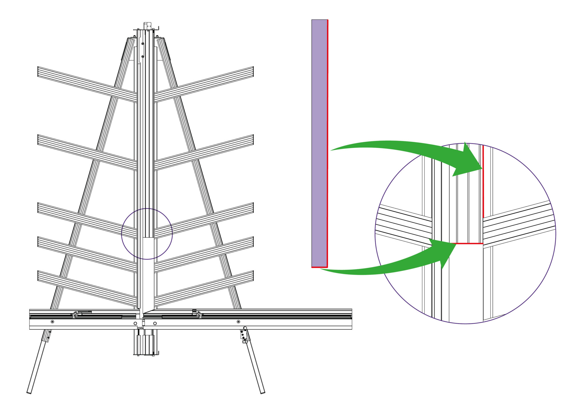
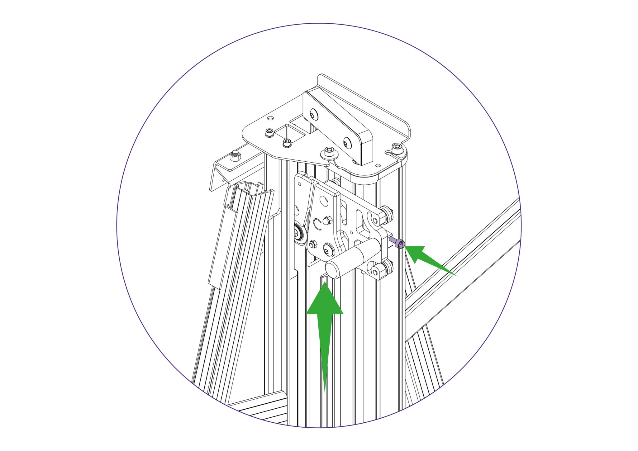
Loosen the two screws using the 6mm Allen key (hex key) on the mount plate of the machine, as indicated. The left hand one needs to be undone enough for the flanged washer (A) to be lifted clear of the top plate, or it can be entirely removed if you prefer but do not remove the other screw. Repeat this at the bottom end of the machine.
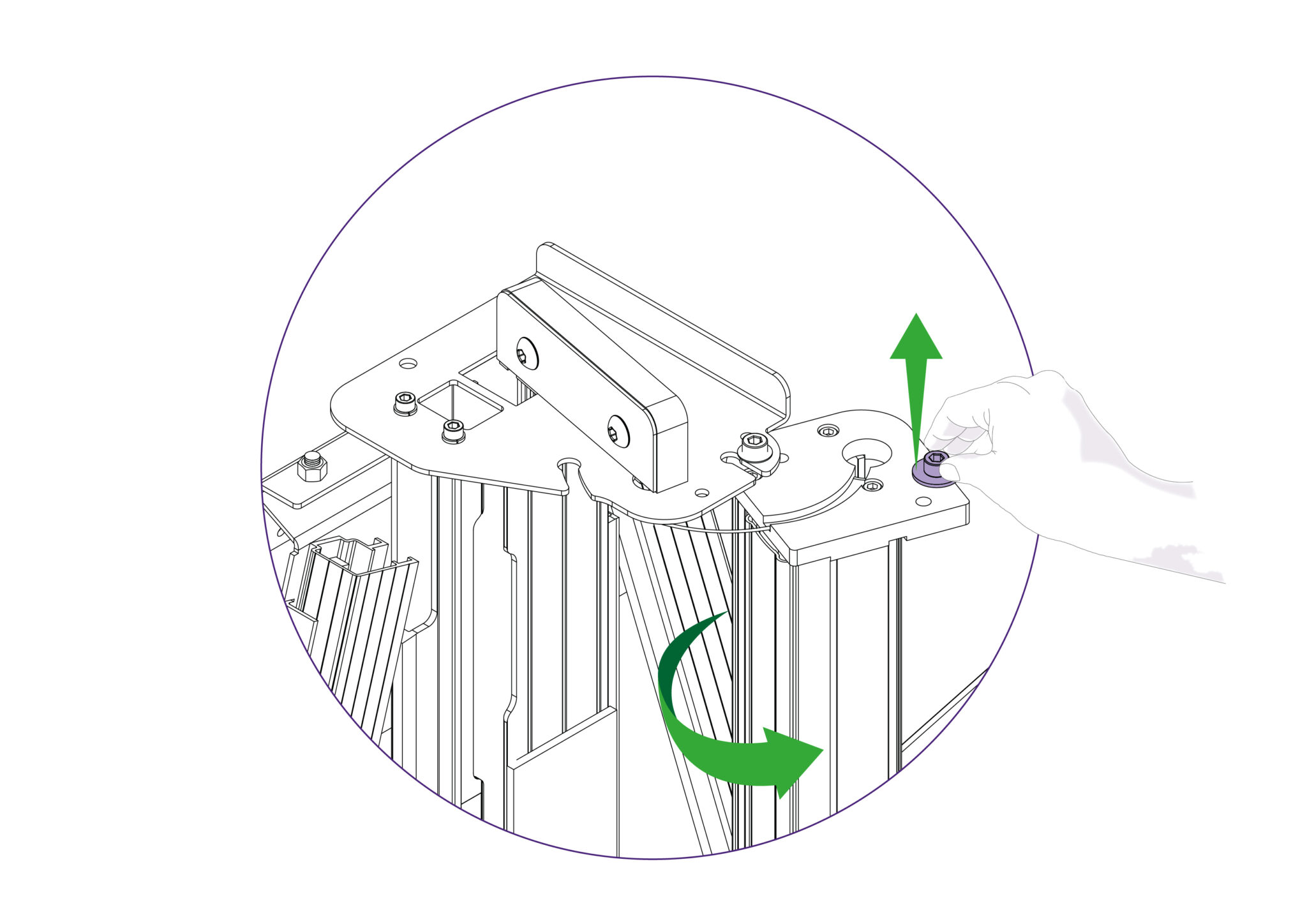
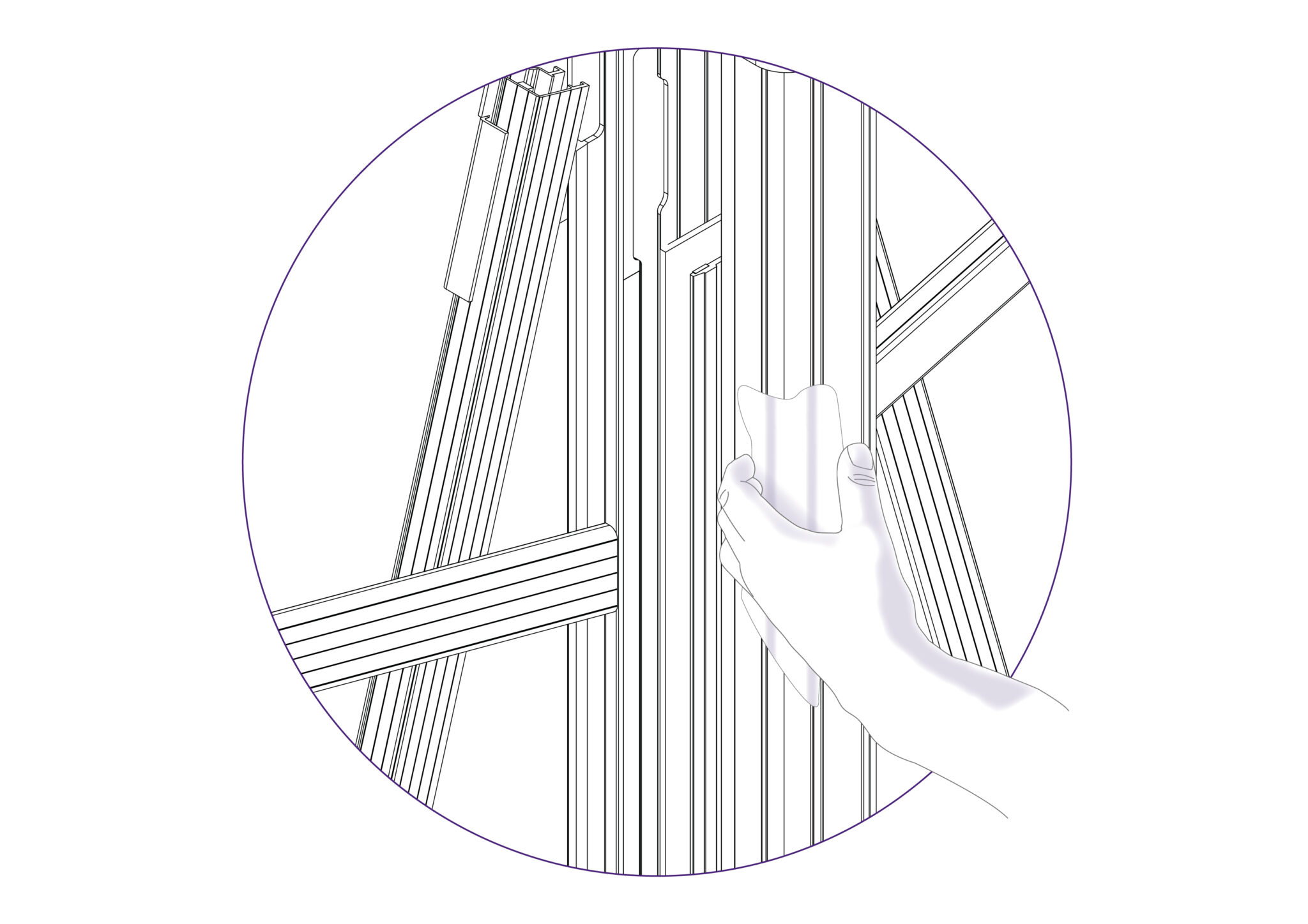
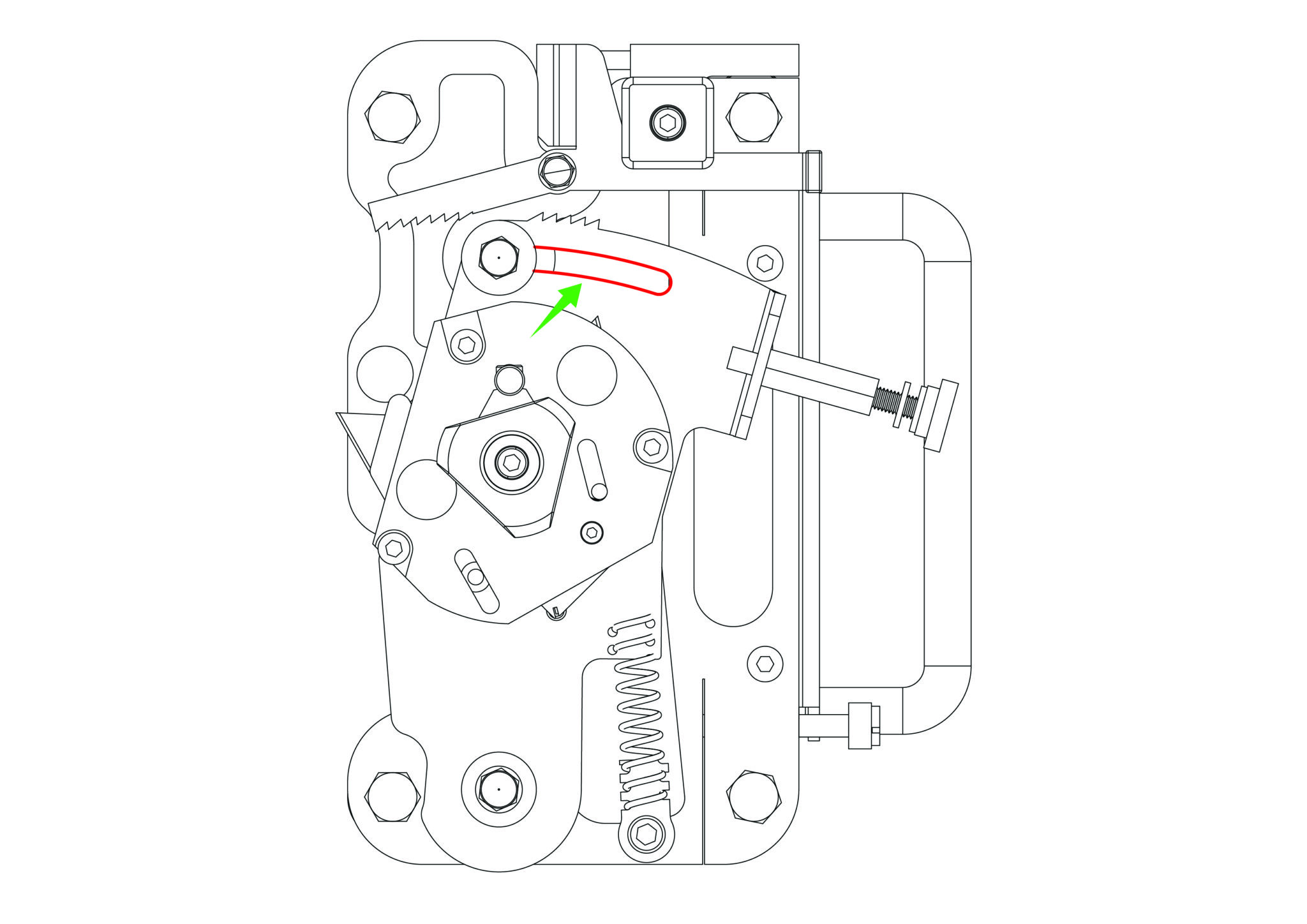
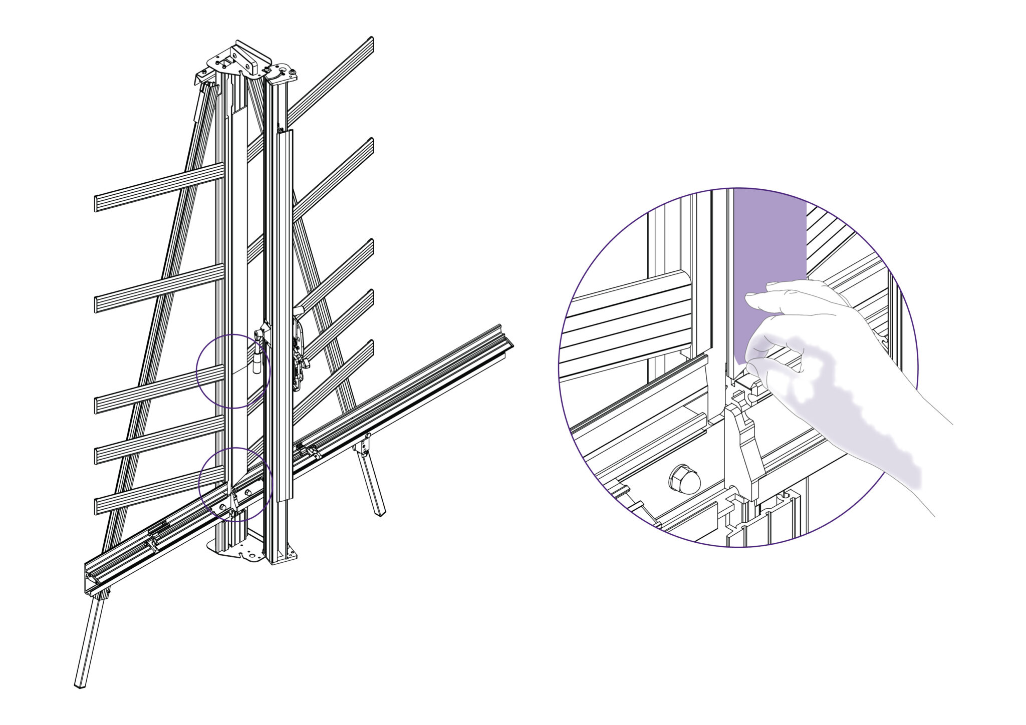
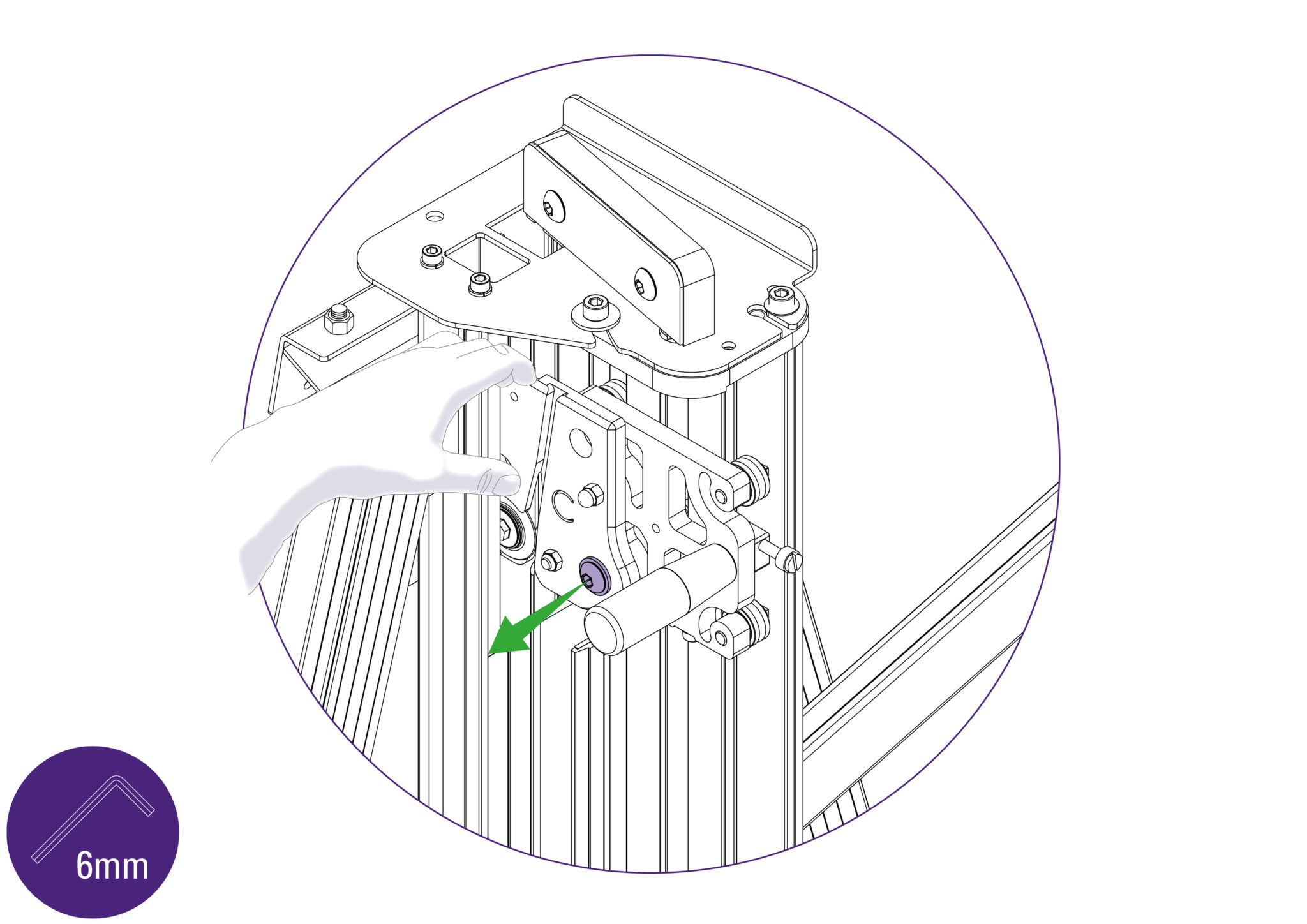
Ensure the clamp is fully open. Then whilst lifting the flanged washer clear with one hand, take hold of the Slideway and twist it out as shown. Once the flanged washer is clear of the top plate it can be released. It is normal to feel the balance weight cord working against you.
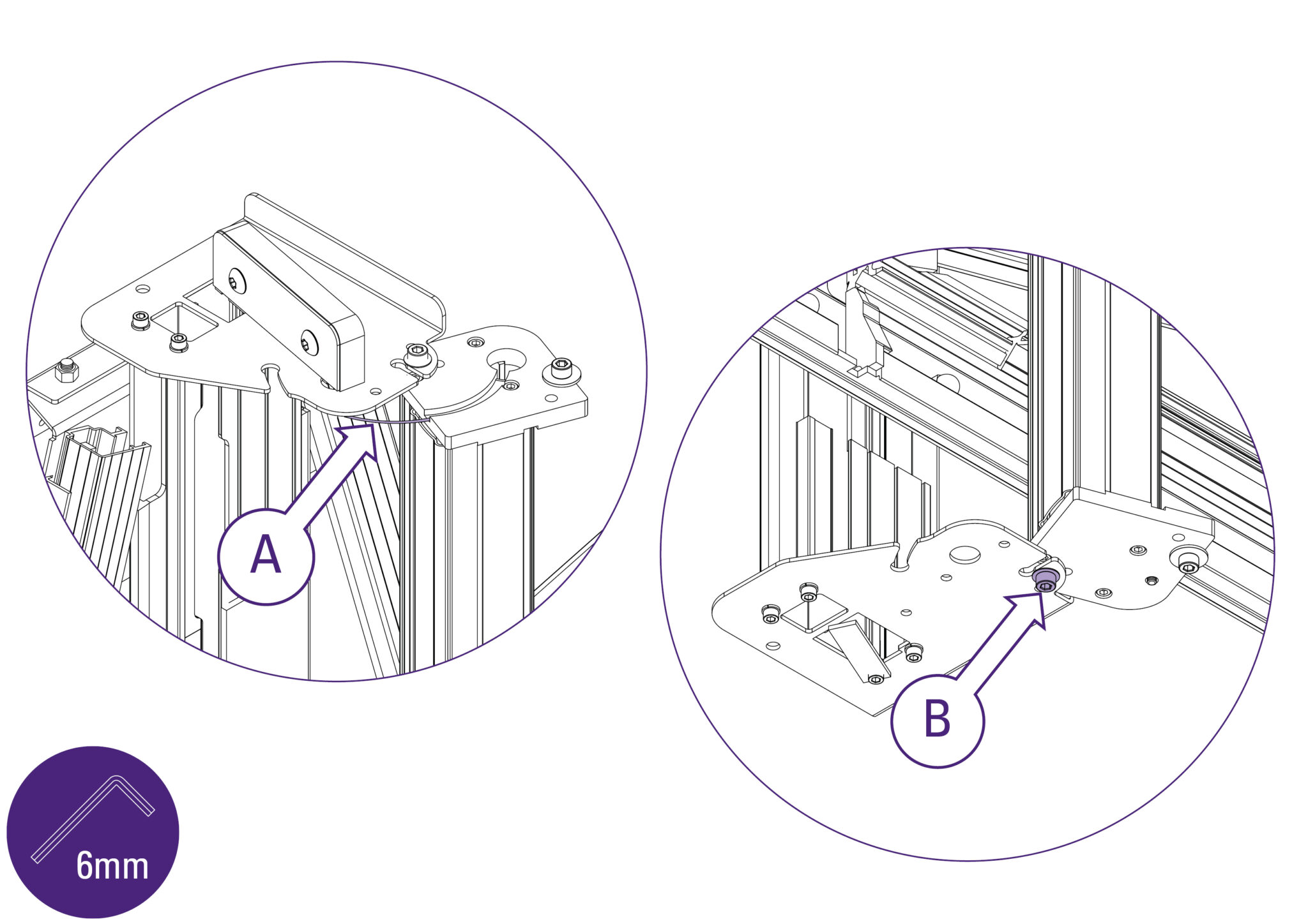
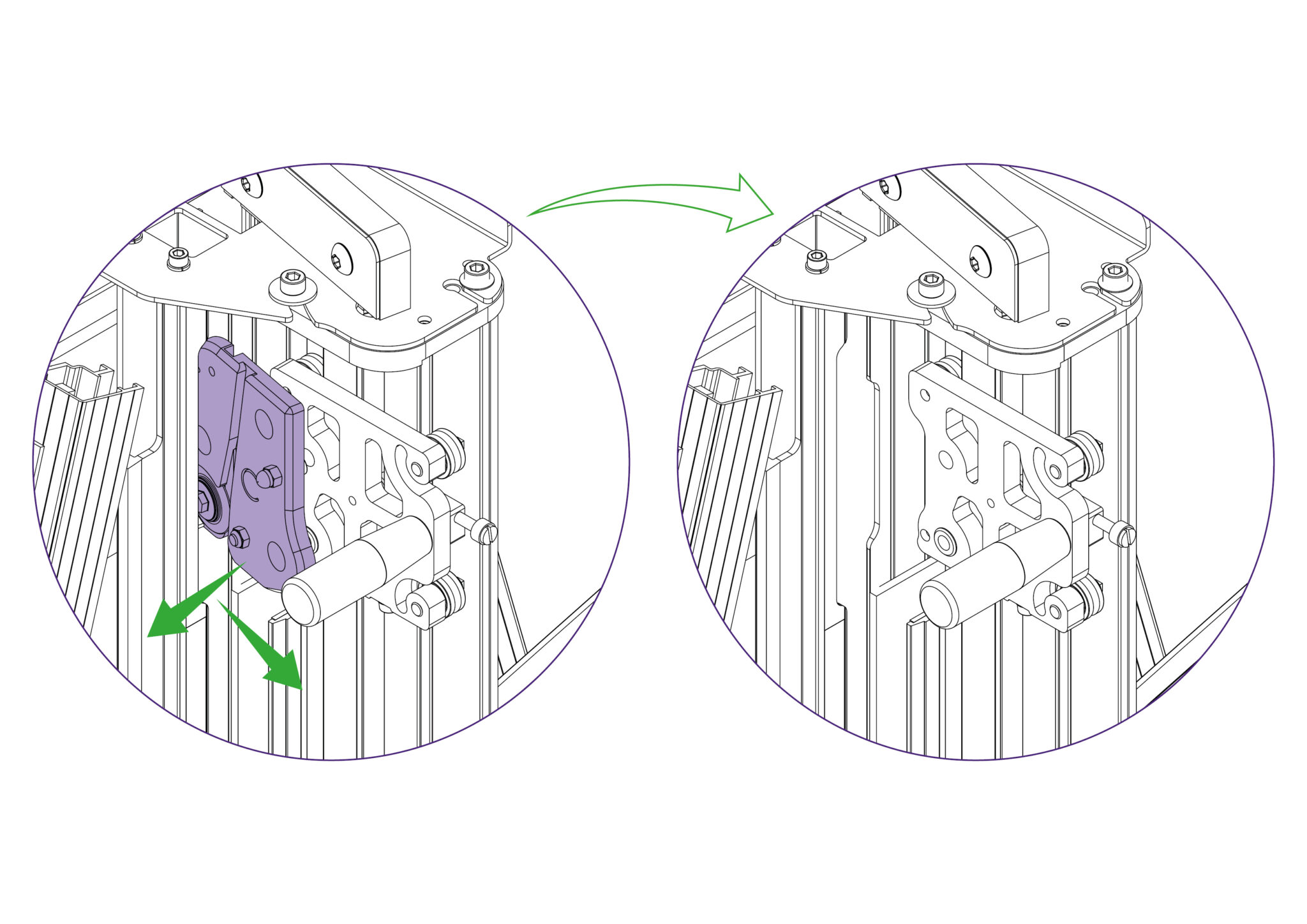
You will feel the balance weight cord (A) working against you and try to twist the slideway back, open the slideway carefully and watch that the balance weight cord (A) does not become trapped. Tighten the bottom Allen screw (B), as shown, to hold the slideway open in the maintenance position.
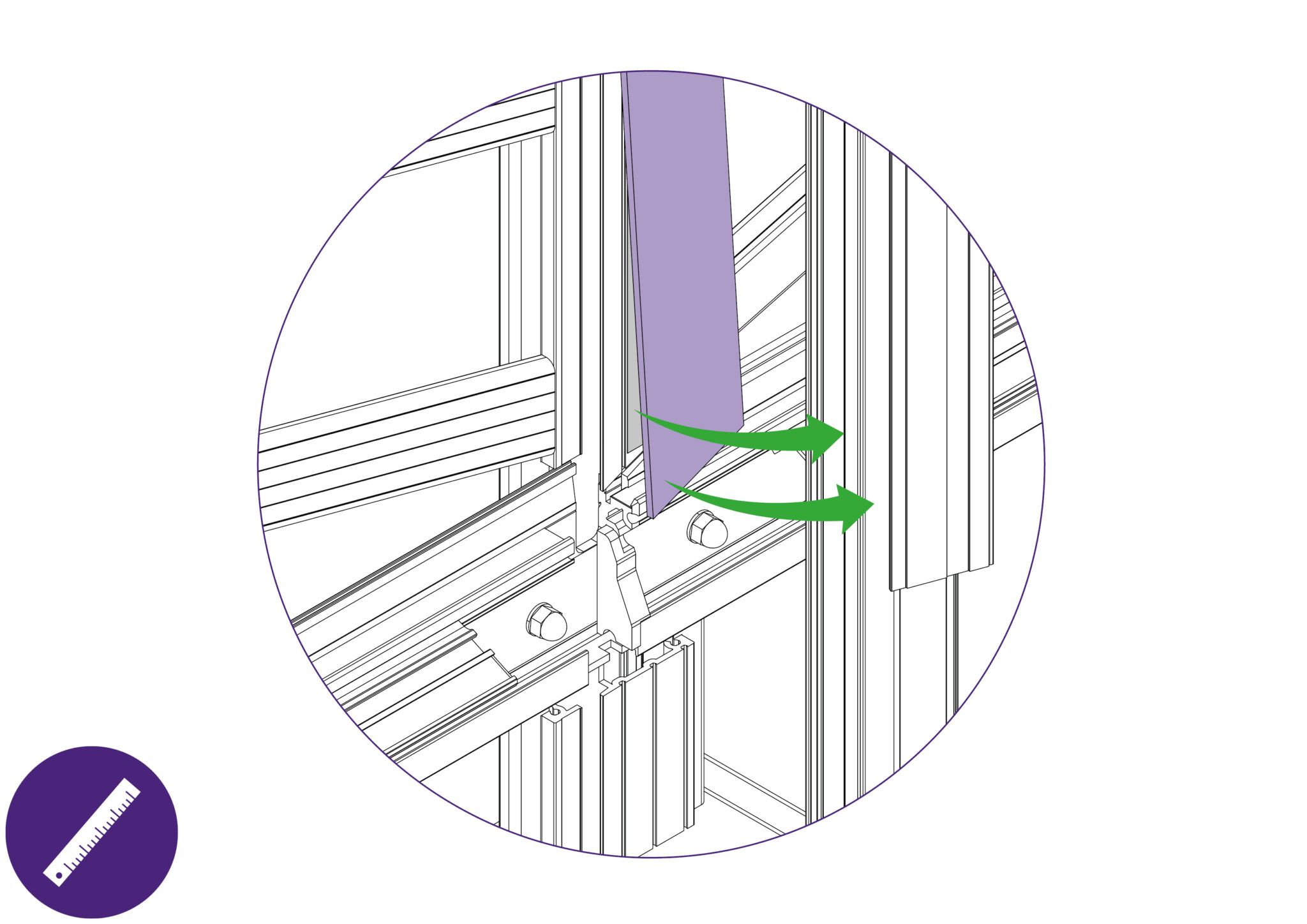
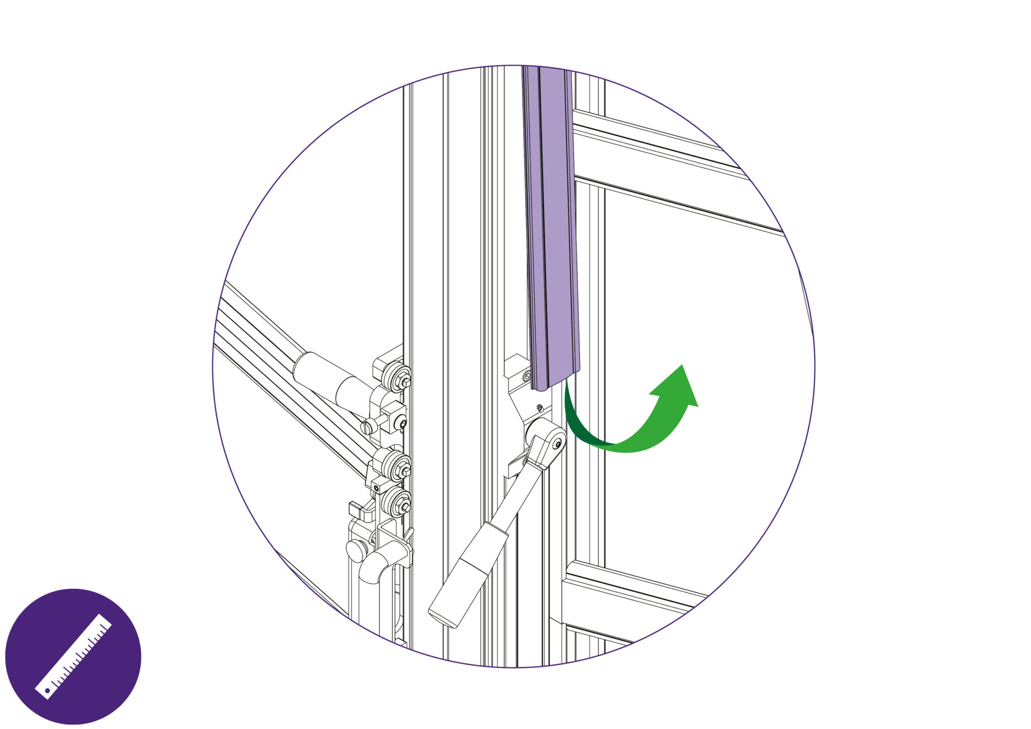
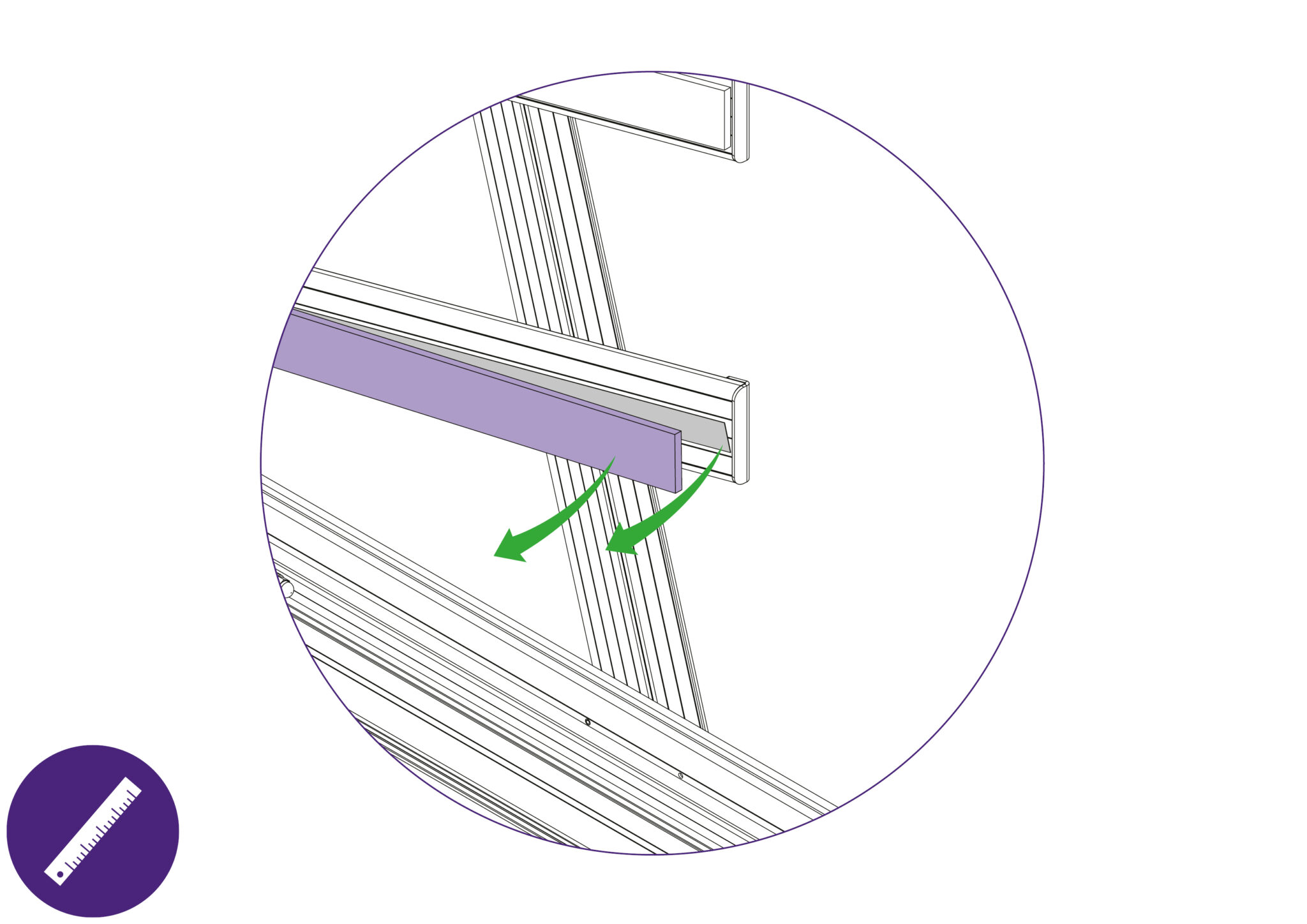
With the Blue Support Board now accessible, slightly remove the edge away using a thin and rigid item such as a ruler. Peel the layers of double sided tape from the Main Body if any tape remains on the surfaces. Clean the surface of the Main Body with white spirit to clear any remnants of adhesive.
Follow through with the same steps for the other Blue Support Board on the Main Body.
Ensure any remnant of cleaning spirit is dried off before proceeding to place the new Blue Support Boards onto the Main Body.
Placing onto the main body:
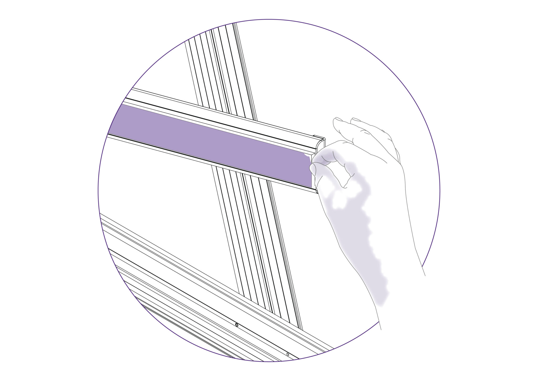
Peel the release paper off the double sided tape and align the angled face of the lower board with the angled face of the Main Body. Ensure that the straight face identified is aligned with the face of the Main Body and that it does not overlap on to the Support Arms.
Proceed to lower the lower Blue Support Board onto the Main Body, starting from the aligned edges.
Peel the release paper off the double sided tape and align the bottom face of the top board. Ensure that the flat face identified is also aligned with the face of the Main Body.
Proceed to lower the top Blue Support Board onto the Main Body, starting from the aligned edges.
Remove the protective film.
Proceed to return the slideway back into operating position and ensure that the cutting head runs up and down the full length of the slideway. Fasten the respective screws tightly.
Move the multi-tool cutter to a comfortable height and lock it in position using the white nylon locking screw. Ensure that this is done tightly.
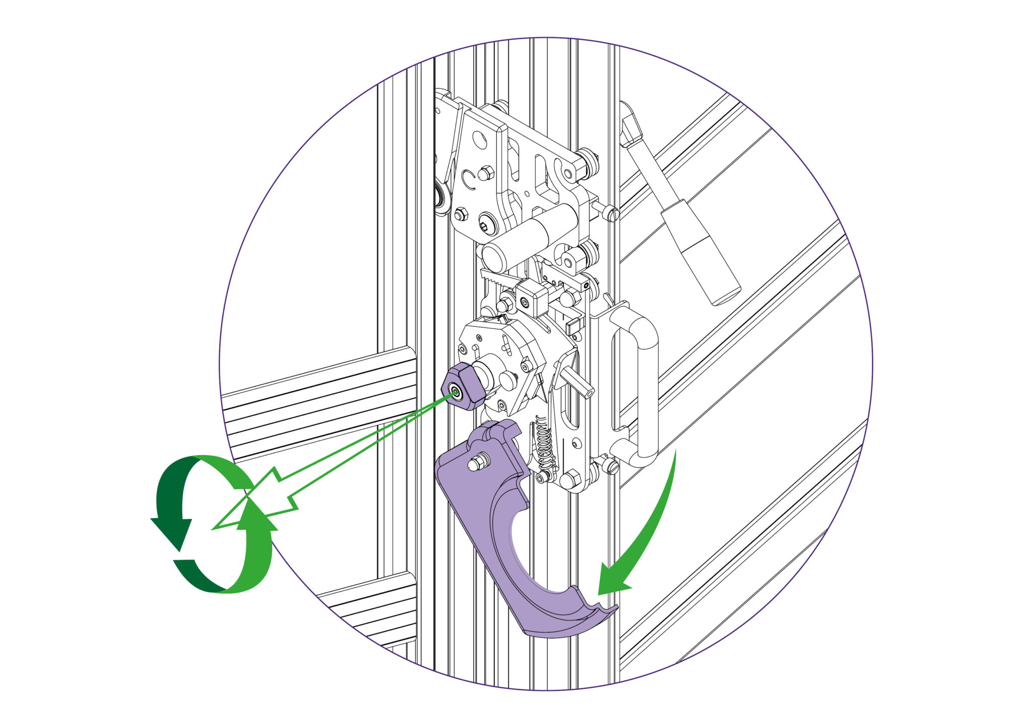
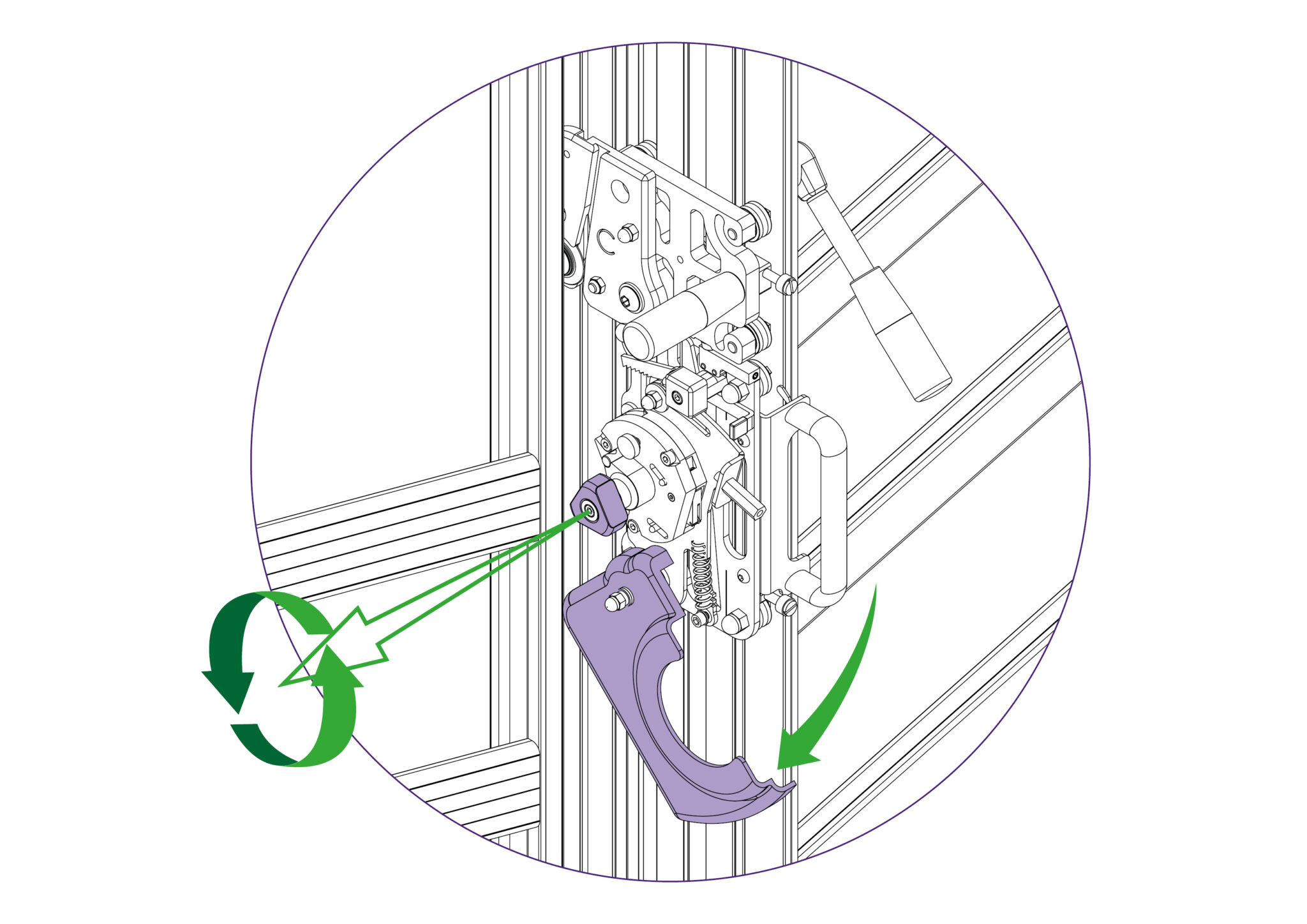
Unlock and swing down the cutter guard. Then rotate the turret so the cutting blade is facing towards you.
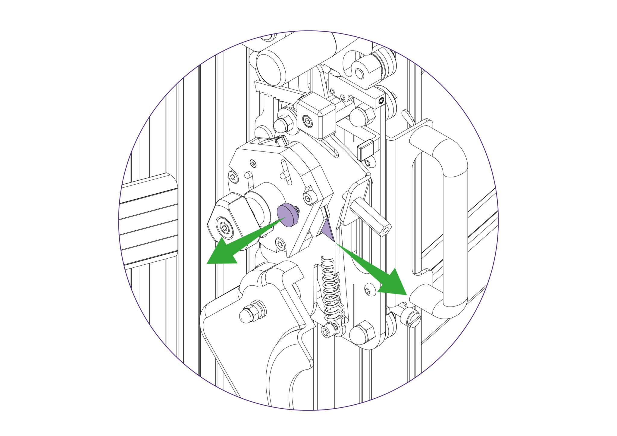
To change the cutting blade, loosen the blade clamping screw to release the blade.
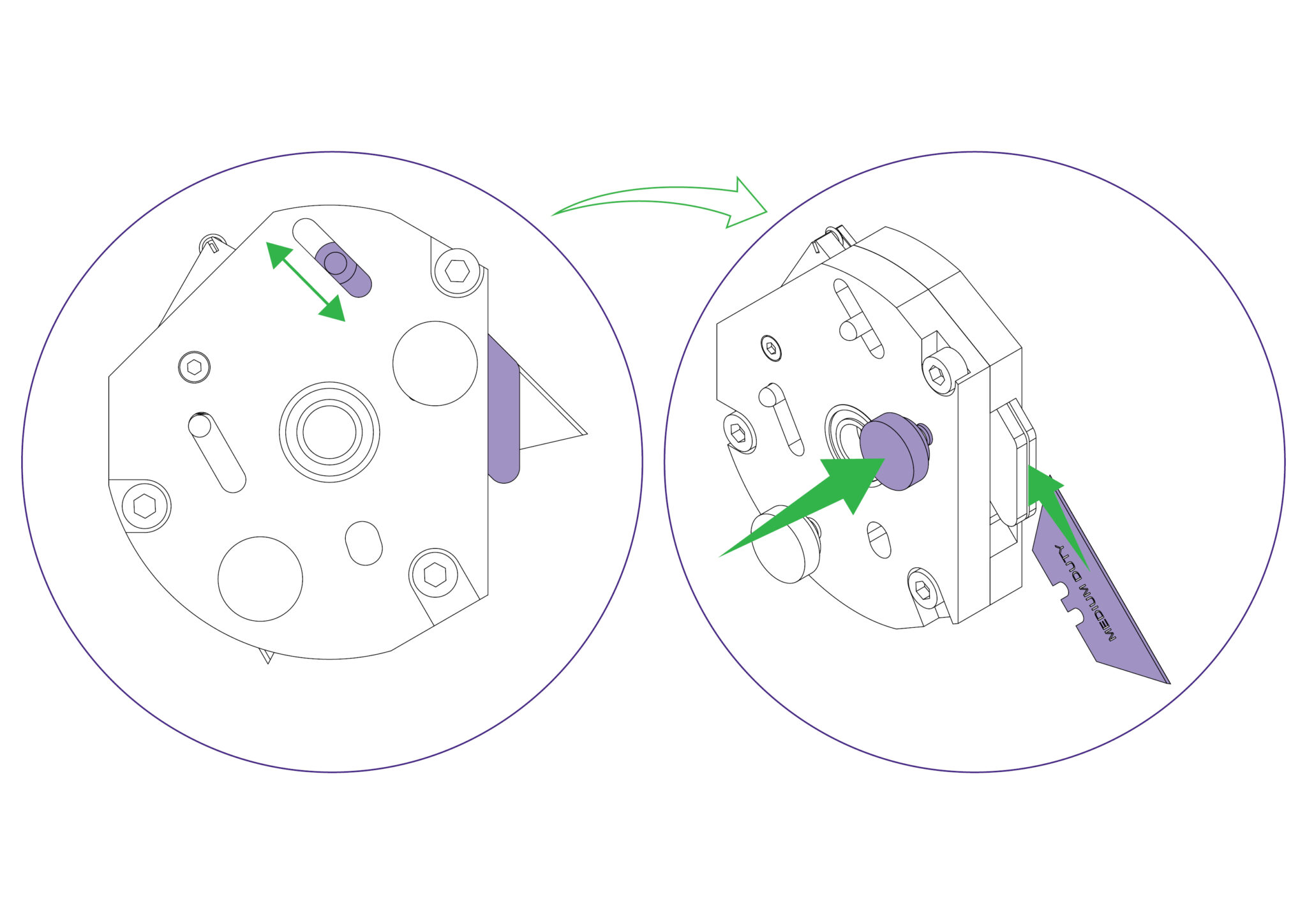
Change or turn over the blade, insert it back into the turret as far as it will go. At this point the position of the blade support plates can be adjusted to suit the thickness of material being cut, and further tightening of the screw will clamp the blade in position.
Rotate the turret back to the cutting position and check the blade support plates with respect to the thickness of the material being cut.
Replace the guard, ensuring it is locked closed.

Move the multi-tool cutter to a comfortable height and lock it in position using the white nylon locking screw. Ensure that this is done tightly.
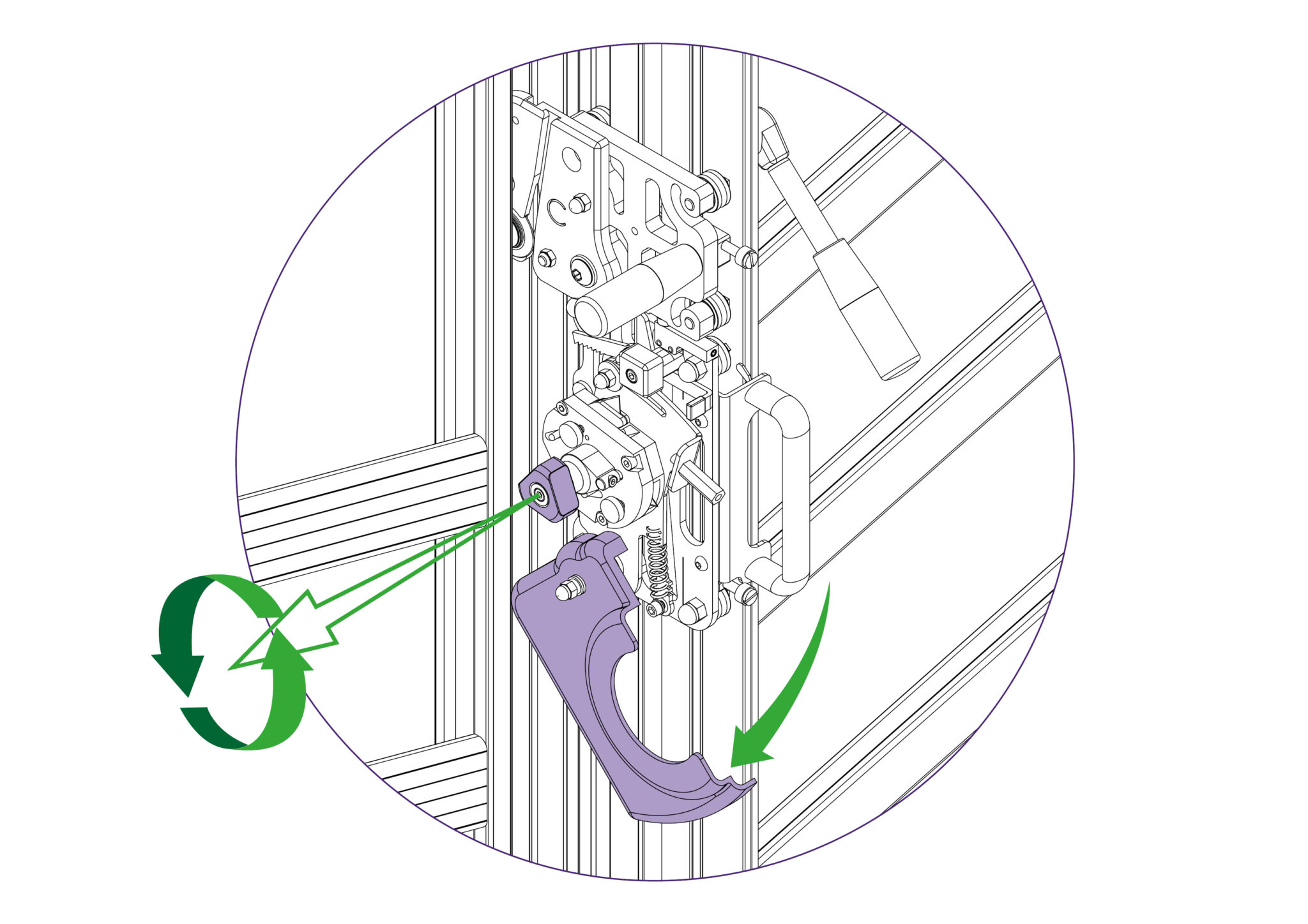
Unlock and swing down the cutter guard. Then rotate the turret so the scoring blade is facing towards you.
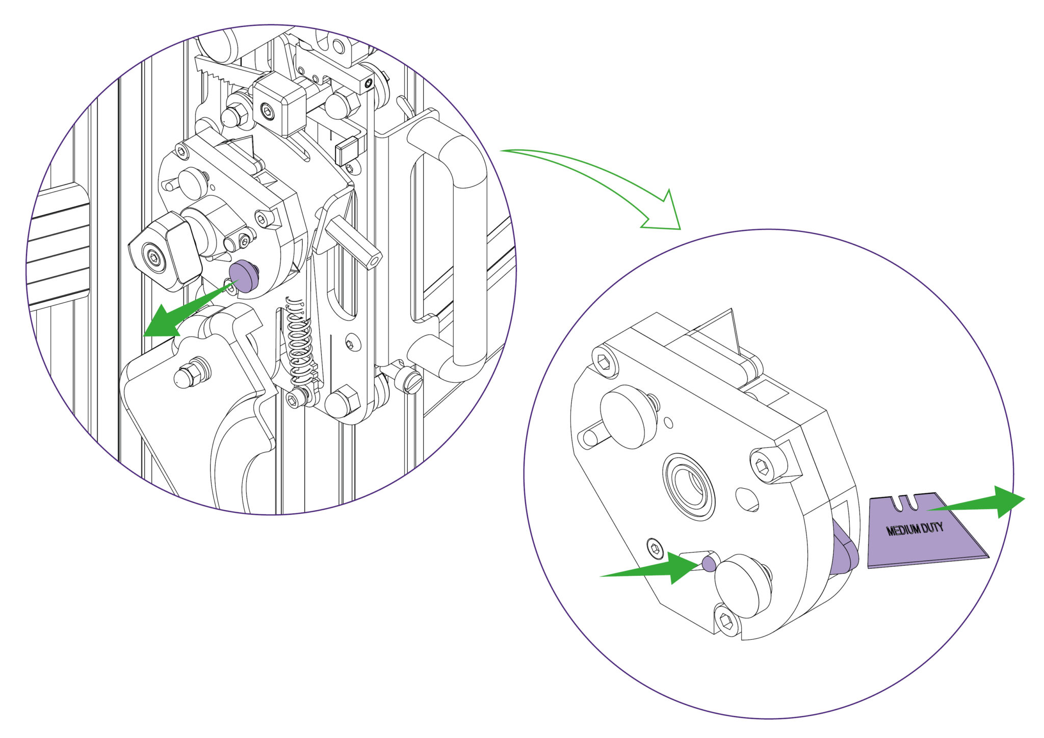
Release the blade clamping screw. Eject the medium duty utility blade using the black ejector pin.
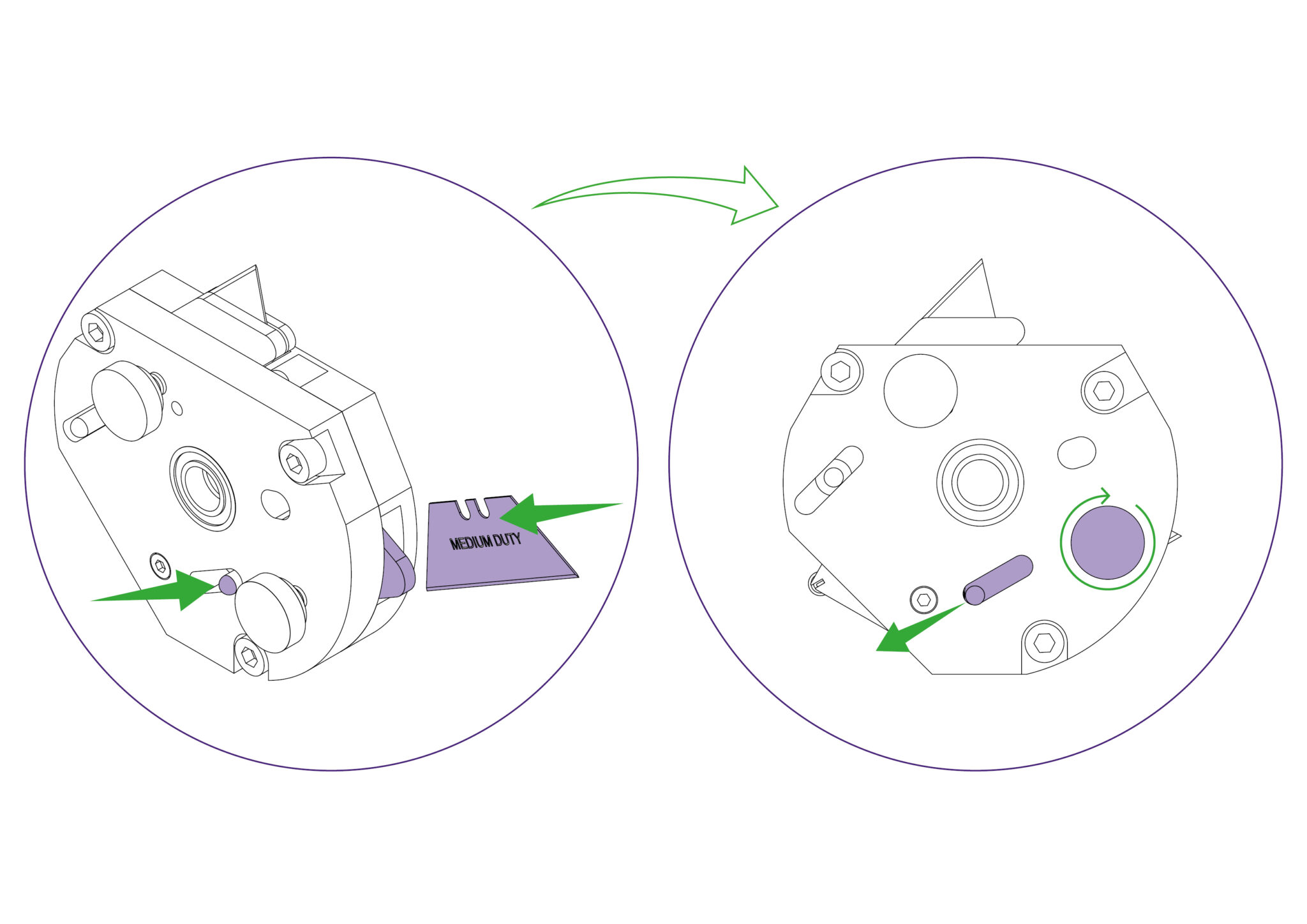
Replace the blade to the right of the clamping plate, push the blade in as far as it will go, and tighten the blade clamping screw.
Rotate the turret back to the scoring position. Replace the guard ensuring it is locked closed.
Move the multi-tool cutter to a comfortable height and lock it in position using the white nylon locking screw. Ensure that this is done tightly.
Unlock and swing down the cutter guard. Then rotate the turret so the glass wheel is facing towards you.
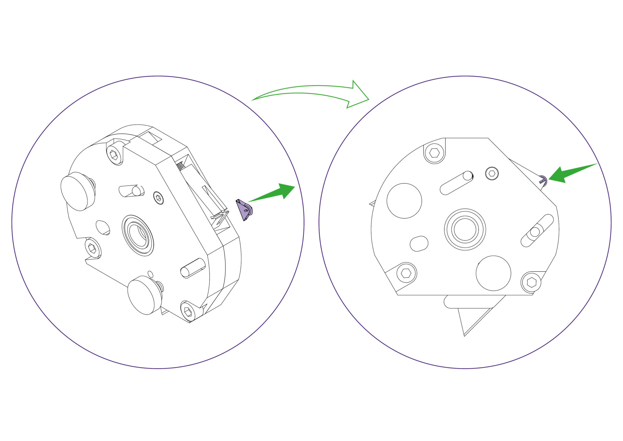
A small screwdriver or piece of stiff wire (opened paperclip) can be used to push the edge of the triangular clip and rotate it out of the groove. Pull the clip to remove the wheel with it. Then replace it with the new wheel and clip assembly.
Rotate the turret back to the glass cutting position. Replace the guard ensuring it is locked closed.
Move the twin wheel cutter to the top of the machine (adjacent to the open channel) and lock it in position using the white nylon locking screw. Ensure that this is done tightly.
Hold the twin wheel cutter on to the Cutting Head whilst removing the screw with a 6mm Allen Key.
Slide the twin wheel cutter out through the open channel in the main body and lift it out. Reverse the procedure to fit the replacement twin wheel cutter, ensuring it is properly located flat against the Cutting Head before fastening the screw with the 6mm Allen Key.
Do not wipe the Squaring Arm channels or remove any debris with fingers, as it may contain sharp particles such as glass.
Use a vacuum cleaner if possible. If a soft brush is used, work slowly and do not allow particles to flick off the bristles.
Guide rods and rollers:
Wipe using cleaning solvent on a cloth, and lubricate the surfaces very lightly with petroleum jelly. The axles of the rollers are lubricated and sealed for life and need no further attention.
Lubrication frequency: After 2 weeks of use and then every month thereafter (except on axles of rollers).
Ratchet system:
Use a light oil (3 in 1), one or two drops on the pivot point and one drop on the ratchet teeth.
Lubrication frequency: After 2 weeks of use and then every month thereafter.
Balance weight:
Silicon Lubricant sprayed in from the top of the balance weight opening whilst the Twin Wheel Cutting Head is parked at the top of the machine.
Lubrication frequency: After 2 weeks of use and then every month thereafter.
Ratchet release bar:
Smear edge with petroleum jelly.
Lubrication frequency: After 2 weeks of use and then every month thereafter.
Swinging Arm:
Petroleum jelly around curved slot.
Lubrication frequency: After 2 weeks of use and then every month thereafter.
The pressure of the clamp is in relation to the amount of pressure applied to the operating handle, however in time the maximum clamping pressure can reduce due to wear on the friction block (hidden within the machine).
Compensation for this can be made by adjusting the two small grub screws (labelled B) in the operating handle housing as shown. Turning the screws lightly clockwise until they stop moving and then undoing them by quarter of a turn should provide an acceptable pressure, but further small adjustments can be made to increase or decrease the pressure as required.
When cutting tough materials it is essential that the clamping system operates at its’ optimum, the moving clamp bar must press evenly onto the board being cut and not clamp it only at the top or bottom.
To check for parallel clamping, use 2 pieces of A4 paper, place one under the bottom end of the clamp and hold the other at the top end whilst depressing the clamp handle. Then check that the clamp firmly grips the pieces of paper. If it does not clamp both pieces firmly, follow the steps below.
Open the clamp by at least 1-2mm and remove the plastic cover strip situated above the clamp handle it just clips out of place, use the end of a small steel rule to lever it from its’ groove.
The clamp adjuster is at the top end of the push rod and is locked in position by two locking nuts.
The top nut has a normal right-handed thread, slacken it using a 10mm wrench by turning it counter clockwise when looking from below.
Now slacken the bottom nut, which has a left hand thread and should be turned clockwise when viewed from below.
The ‘adjuster’ is the hexagonal bar between the two nuts, and by turning it with the spanner it alters the clamps alignment with the back of the machine.
Rotate the adjuster whilst observing the clamp from the side and bring the clamp into parallel.
Repeat the initial check using the 2 pieces of A4 paper, to ensure the clamp has been brought into parallel.
Once parallel is confirmed, tighten the two locking nuts whilst holding the adjuster in position with the second spanner. Then operate the clamp a few times and check/adjust further if necessary.
Finally, replace the plastic cover strip.
The Blue Support Boards on the Main Body and Support Arms offer an element of protection to materials being cut, in particular coated glass surfaces. Over the machine’s lifetime it could be expected that these Blue Support Boards could experience wear and may need replacing.
Removing from the support arm:
Slightly remove the edge of the Blue Support Board using a thin and rigid item such as a ruler. Peel the layers of double sided tape from the support arm if any tape remains on the surfaces. Clean the surface of the support arm with white spirit to clear any remnants of adhesive.
Ensure the surface is clean and dry before fitting the new Blue Support Boards onto the Support Arms.
Placing onto the support arms:
Peel the release paper from the adhesive face and align the angled face of the board with the angled face of the Support Arm that does not have the end cap attached. Ensure that the board in central to the Support Arm and that it does not overlap on to the Main Body face.
Proceed to lower the Blue Support Board onto the Support Arm surface, starting from the aligned edge.
Remove the protective film.
Removing from the main body:
Loosen the two screws using the 6mm Allen key (hex key) on the mount plate of the machine, as indicated. The left hand one needs to be undone enough for the flanged washer (A) to be lifted clear of the top plate, or it can be entirely removed if you prefer but do not remove the other screw. Repeat this at the bottom end of the machine.
Ensure the clamp is fully open. Then whilst lifting the flanged washer clear with one hand, take hold of the Slideway and twist it out as shown. Once the flanged washer is clear of the top plate it can be released. It is normal to feel the balance weight cord working against you.
You will feel the balance weight cord (A) working against you and try to twist the slideway back, open the slideway carefully and watch that the balance weight cord (A) does not become trapped. Tighten the bottom Allen screw (B), as shown, to hold the slideway open in the maintenance position.
With the Blue Support Board now accessible, slightly remove the edge away using a thin and rigid item such as a ruler. Peel the layers of double sided tape from the Main Body if any tape remains on the surfaces. Clean the surface of the Main Body with white spirit to clear any remnants of adhesive.
Follow through with the same steps for the other Blue Support Board on the Main Body.
Ensure any remnant of cleaning spirit is dried off before proceeding to place the new Blue Support Boards onto the Main Body.
Placing onto the main body:
Peel the release paper off the double sided tape and align the angled face of the lower board with the angled face of the Main Body. Ensure that the straight face identified is aligned with the face of the Main Body and that it does not overlap on to the Support Arms.
Proceed to lower the lower Blue Support Board onto the Main Body, starting from the aligned edges.
Peel the release paper off the double sided tape and align the bottom face of the top board. Ensure that the flat face identified is also aligned with the face of the Main Body.
Proceed to lower the top Blue Support Board onto the Main Body, starting from the aligned edges.
Remove the protective film.
Proceed to return the slideway back into operating position and ensure that the cutting head runs up and down the full length of the slideway. Fasten the respective screws tightly.
Move the multi-tool cutter to a comfortable height and lock it in position using the white nylon locking screw. Ensure that this is done tightly.
Unlock and swing down the cutter guard. Then rotate the turret so the cutting blade is facing towards you.
To change the cutting blade, loosen the blade clamping screw to release the blade.
Change or turn over the blade, insert it back into the turret as far as it will go. At this point the position of the blade support plates can be adjusted to suit the thickness of material being cut, and further tightening of the screw will clamp the blade in position.
Rotate the turret back to the cutting position and check the blade support plates with respect to the thickness of the material being cut.
Replace the guard, ensuring it is locked closed.
Move the multi-tool cutter to a comfortable height and lock it in position using the white nylon locking screw. Ensure that this is done tightly.
Unlock and swing down the cutter guard. Then rotate the turret so the scoring blade is facing towards you.
Release the blade clamping screw. Eject the medium duty utility blade using the black ejector pin.
Replace the blade to the right of the clamping plate, push the blade in as far as it will go, and tighten the blade clamping screw.
Rotate the turret back to the scoring position. Replace the guard ensuring it is locked closed.
Move the multi-tool cutter to a comfortable height and lock it in position using the white nylon locking screw. Ensure that this is done tightly.
Unlock and swing down the cutter guard. Then rotate the turret so the glass wheel is facing towards you.
A small screwdriver or piece of stiff wire (opened paperclip) can be used to push the edge of the triangular clip and rotate it out of the groove. Pull the clip to remove the wheel with it. Then replace it with the new wheel and clip assembly.
Rotate the turret back to the glass cutting position. Replace the guard ensuring it is locked closed.
Move the twin wheel cutter to the top of the machine (adjacent to the open channel) and lock it in position using the white nylon locking screw. Ensure that this is done tightly.
Hold the twin wheel cutter on to the Cutting Head whilst removing the screw with a 6mm Allen Key.
Slide the twin wheel cutter out through the open channel in the main body and lift it out. Reverse the procedure to fit the replacement twin wheel cutter, ensuring it is properly located flat against the Cutting Head before fastening the screw with the 6mm Allen Key.
Ⓒ Keencut 2020 | Baird Rd, Corby NN17 5ZA United Kingdom | Contact us
Created by DeType | Privacy | Website Disclaimer | Terms & Conditions