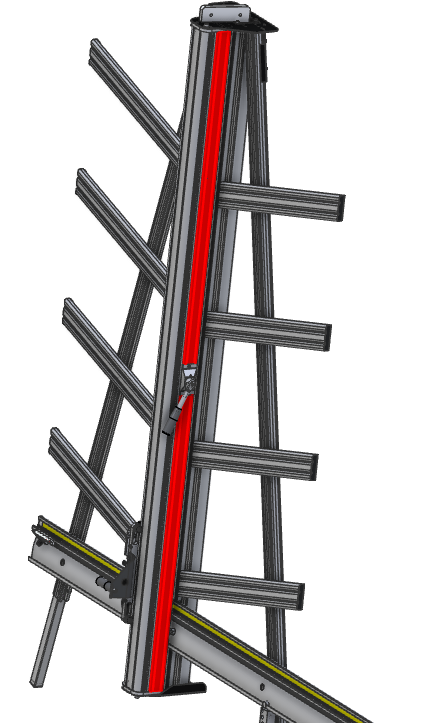
How to replace the pivot housing assembly on the SteelTrak 165 / 210 and Excalibur 6000 only
To do this you will need the SteelTrak & Excalibur pivot housing assembly >
Tools required:
- Allen (hex) key 4, 5 & 6mm
- Small flat screwdriver or steel rule
- 10mm open ended spanner/wrench
- Hand protection
- Steps to access the top of the machine
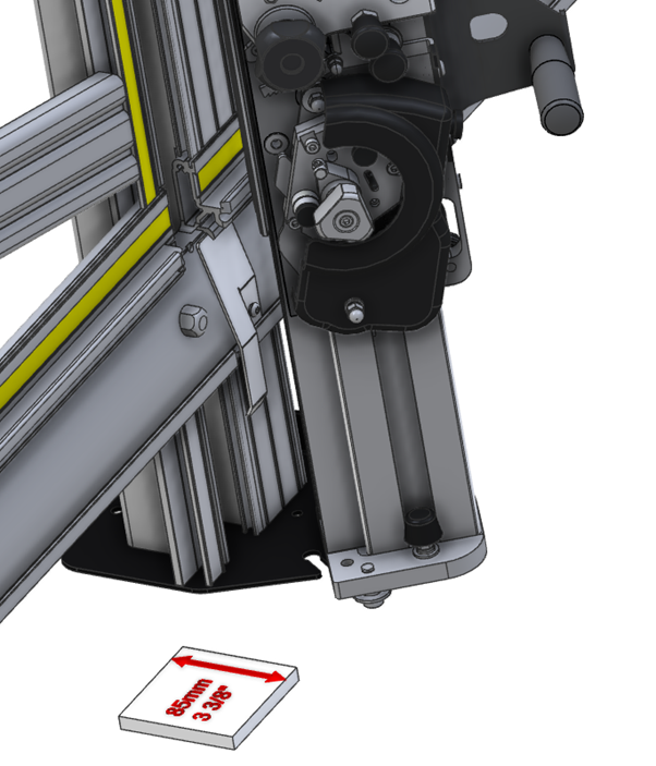
- PVC Foamboard (or a similar) spacer cut to 85mm – 3 3/8” wide
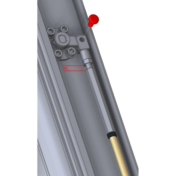
- Rotate the adjuster to close the gap between itself and the forked fitting as much as possible, sometimes this can be done using your fingers rather than the spanner/wrench.
- Remove the pin from the lower forked fitting.
- Remove the push rod, on some versions the push rod may need to be flexed slightly to remove it.
- The SteelTrak 165 and 210 have a maintenance position whereby the clamp can be accessed without removing the cutter bar from the machine.
- Check all blades have been removed from the cutting head.
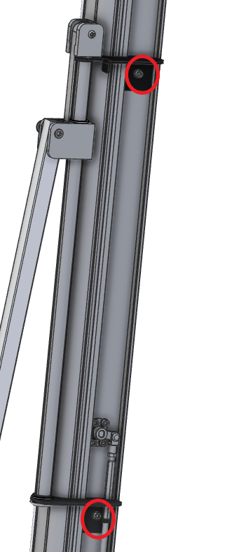
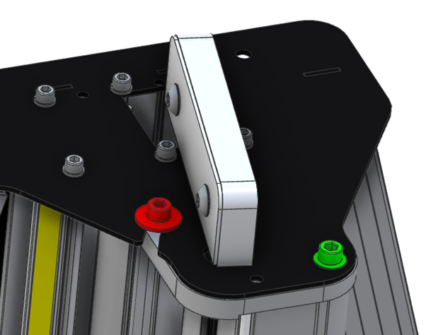
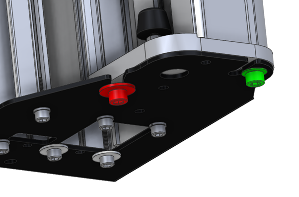
- Using steps to access the top of the machine, using a 6mm Allen (hex) key remove the red screw/washer and loosen the green screw.
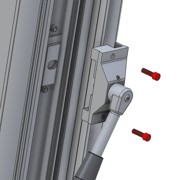
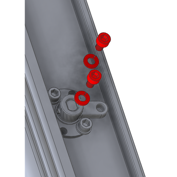
- Rotate the cutter bar out of the maintenance position then remove the other two screws from each pivot assembly and take it out from the hole in the cutter bar. Replace with new pivot housings and the same two screws.
- Return to the maintenance position and reassemble in the reverse order but care needs to be taken in the following areas:
-
- When fitting the clamp bar introduce the bottom pressure roller into its groove and push the roller down into the groove with your finger as you push the clamp bar into position. Introduce the top pressure roller into its groove and again push it down with your finger to locate it, push the clamp bar all the way into the cutter bar.
- If necessary use the 10mm spanner/wrench to adjust the clamp bar to make it parallel to the back of the main machine.
- Once fully assembled adjust the maximum clamping pressure. Using the 3mm Allen (hex) key, turn both grub screws on the face of the clamp handle housing clockwise until they stop then undo each screw by ¼ turn, further small adjustments can be made to increase or decrease the maximum clamping pressure as desired.

