
SteelTrak clamp rod assembly
Before you start
Before starting any work, check the machine is firmly fixed to the wall or freestanding leg and that you have the following equipment:
- A set of steps, high enough to reach the top of the machine
- A small slotted screwdriver or steel ruler
- 4mm (1/8″) and 5mm (3/16″) Allen keys (hex keys),
- 10mm (3/8″) open-ended spanner (wrench)
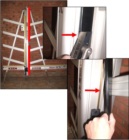
1. Remove the cover strips
The two black plastic cover strips are fixed on the right hand side of the slideway, they are shown in red in the picture. Use a small screwdriver or steel ruler to prise them off.
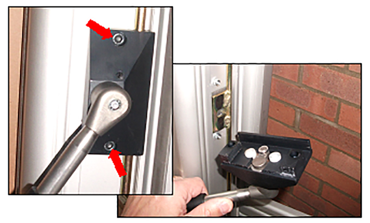
2. Remove the clamp housing assembly
Remove the two screws using a 5mm (3/16″) Allen key (hex key). As you remove the assembly, make sure the inside faces upwards to prevent parts falling to the floor.
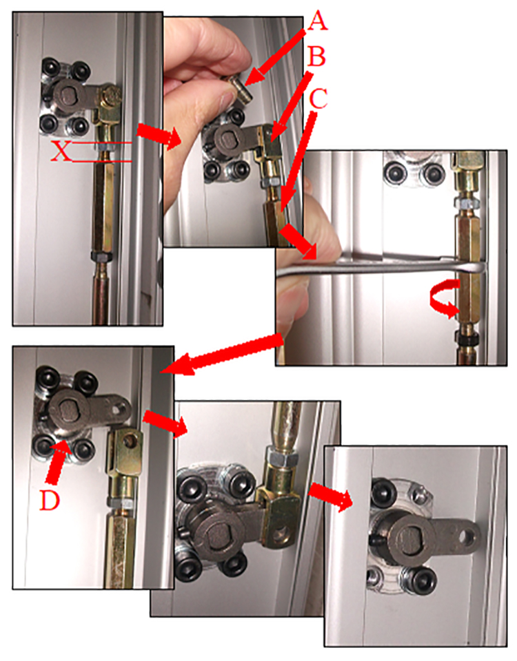
3. Remove the clamp push rod
At the top of the push rod there is an adjuster (C), which aligns the main clamp bar so it clamps evenly at the top and bottom. If this needs adjusting, rather than removal please turn to the section on ‘Adjusting the clamp’.
Firstly, measure and note dimension X shown on the picture. In order to remove the push rod, pull the pin (A) out of the clevis (B) at the top of the push rod and loosen the two locking nuts, the black one has a left hand thread, using a 10mm (3/8″) open ended spanner/wrench.
Rotate the adjuster (C), to close the gap between itself and the clevis (B) as much as possible, sometimes this can be done using your fingers rather than the spanner/wrench.
Remove the pin (A) from the lower clevis (B), then remove the push rod. On some versions, the push rod may need to be flexed slightly to remove it.
To assist with the removal of the main clamp bar, remove the top right and bottom left screws and locking washers from both pivot housings (D) using a 4mm (1/8″) Allen key.
Ⓒ Keencut 2020 | Baird Rd, Corby NN17 5ZA United Kingdom | Contact us
Created by DeType | Privacy | Website Disclaimer | Terms & Conditions