
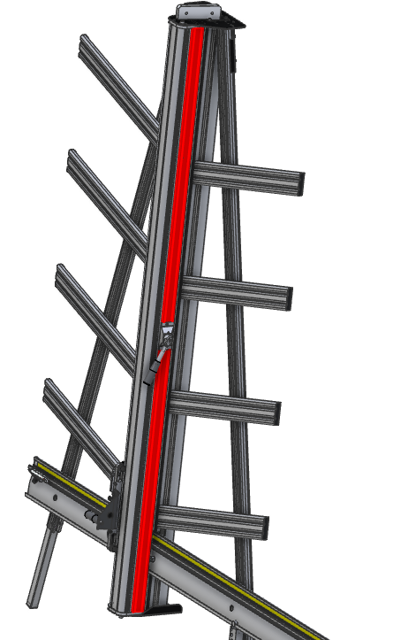
How to replace the pivot housing assembly on the SteelTrak 165 / 210 and Excalibur 6000 only
To do this you will need the SteelTrak & Excalibur pivot housing assembly >
Tools required:
- Allen (hex) key 4, 5 & 6mm
- Small flat screwdriver or steel rule
- 10mm open ended spanner/wrench
- Hand protection
- Steps to access the top of the machine
- PVC Foamboard (or a similar) spacer cut to 85mm – 3 3/8” wide
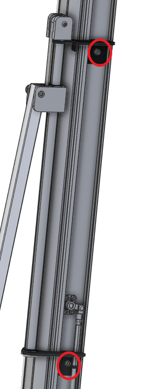
- Using a small screwdriver or steel rule, prise off the black plastic cover strips that are fixed on the right-hand side of the cutter bar. (Shown in red)
- SteelTrak 210 only – Remove the pull bar assembly using a 5mm Allen (hex) key to remove the two screws (circled red).
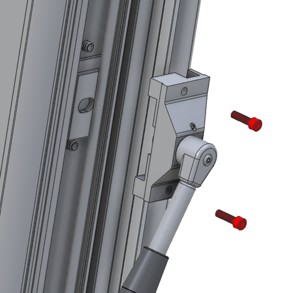
- Remove the clamp handle housing, using a 5mm Allen (hex) key undo the two screws and pull off the assembly ensuring the inside face of the housing points upwards as you do so to prevent internal parts falling to the floor.
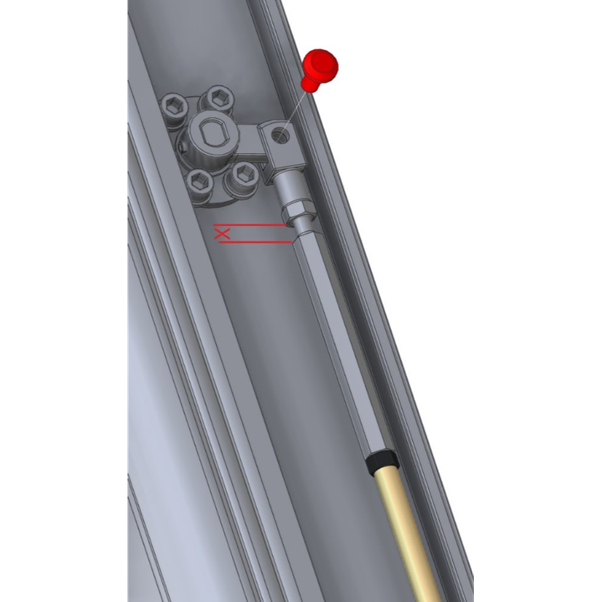
- At the top of the push rod there is an adjuster which aligns the main clamp bar, measure and note dimension X.
- Pull the pin out of the forked fitting and loosen the two locking nuts (the black one has a left-hand thread) using a 10mm open ended spanner/wrench.
- Rotate the adjuster to close the gap between itself and the forked fitting as much as possible, sometimes this can be done using your fingers rather than the spanner/wrench.
- Remove the pin from the lower forked fitting.
- Remove the push rod, on some versions the push rod may need to be flexed slightly to remove it.
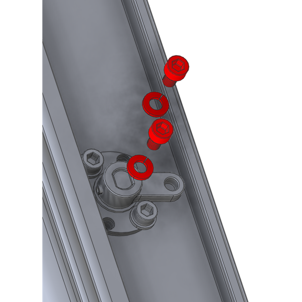
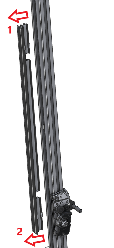
- Remove two of the screws and locking washers from both pivot housing as shown (it is important it is the two shown) using a 4mm Allen (hex) key.
- The SteelTrak 165 and 210 have a maintenance position whereby the clamp can be accessed without removing the cutter bar from the machine.
- Check all blades have been removed from the cutting head.
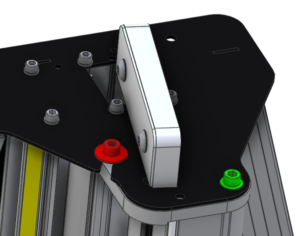
- Using steps to access the top of the machine, using a 6mm Allen (hex) key remove the red screw/washer and loosen the green screw.
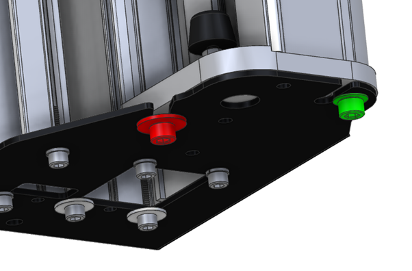
- Repeat at the bottom of the machine but the red screw does not have to be removed, just loosened enough for the washer to be clear of the black steel plate.
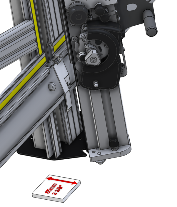
- The cutter bar should now twist to reveal the underside of the clamp bar, the balance weight system will try to close the cutter bar so a spacer made from PVC Foamboard or a similar rigid board cut to 85mm – 3 3/8” wide is used to hold it open.
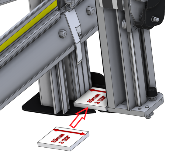
- Twist the cutter bar open by 90° and place the spacer in the bottom of the machine.
- Grip the clamp bar in two hands and pull the top end of it away from the cutter bar.
- Once the top end disengages from its internal roller pull the bottom end clear.
- Note: For reference the black rubber buffer is at the bottom (circled red)
- Take note of the direction the internal lever is pointing (towards the bottom end of the cutter bar).
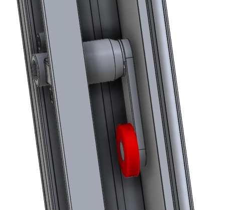
- Prise the black plastic roller from the pivot housing (highlighted red)
- Rotate the cutter bar out of the maintenance position then remove the other two screws from each pivot assembly and take it out from the hole in the cutter bar. Replace with new pivot housings and the same two screws.
- Return to the maintenance position and reassemble in the reverse order but care needs to be taken in the following areas:
-
- When fitting the clamp bar introduce the bottom pressure roller into its groove and push the roller down into the groove with your finger as you push the clamp bar into position. Introduce the top pressure roller into its groove and again push it down with your finger to locate it, push the clamp bar all the way into the cutter bar.
- If necessary use the 10mm spanner/wrench to adjust the clamp bar to make it parallel to the back of the main machine.
- Once fully assembled adjust the maximum clamping pressure. Using the 3mm Allen (hex) key, turn both grub screws on the face of the clamp handle housing clockwise until they stop then undo each screw by ¼ turn, further small adjustments can be made to increase or decrease the maximum clamping pressure as desired.
Ⓒ Keencut 2020 | Baird Rd, Corby NN17 5ZA United Kingdom | Contact us
Created by DeType | Privacy | Website Disclaimer | Terms & Conditions