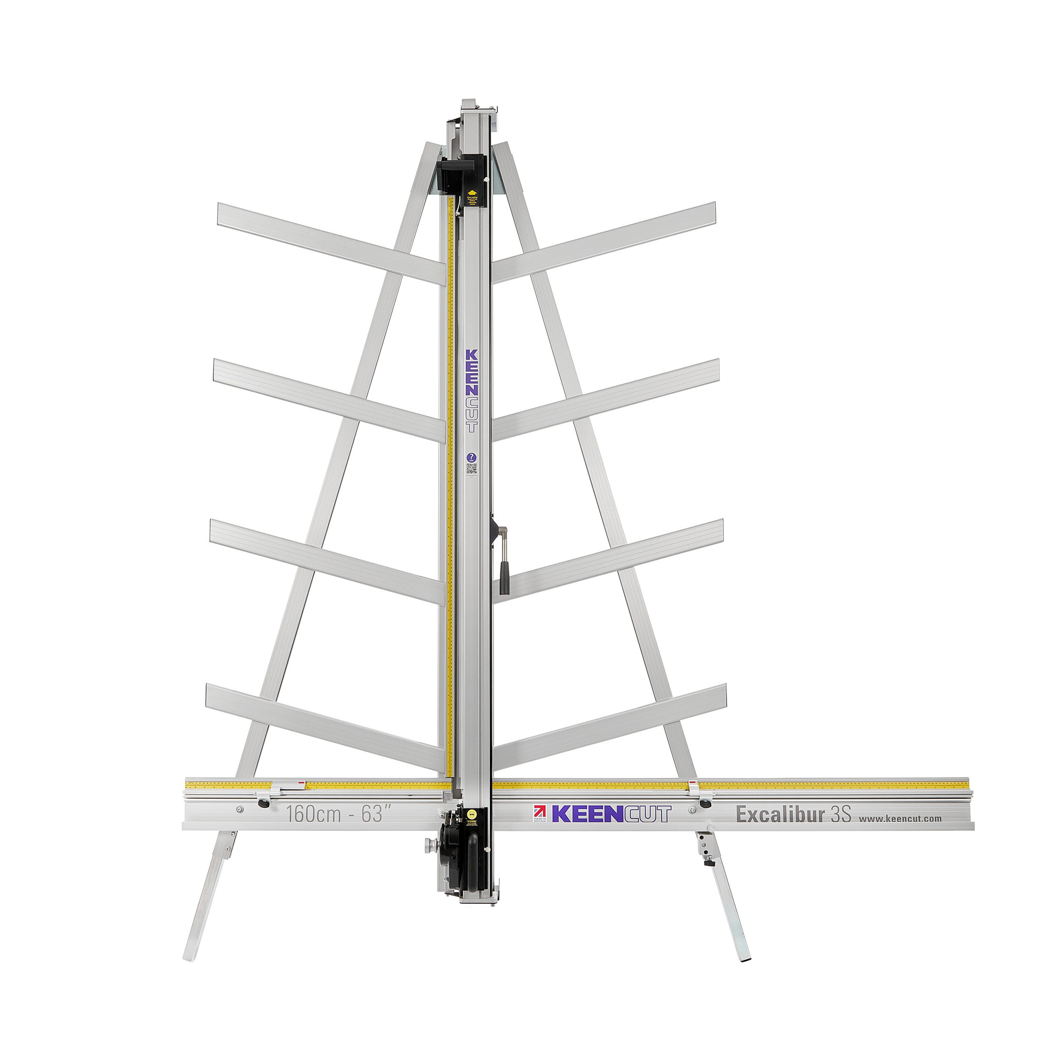
Excalibur 3S installation manual
How to use this guide
Scroll down to view the guide.
You can expand and collapse sections using the + and – icons.
The images in this manual are expandable. Click/tap on them to enlarge.
View PDF version >
Other support resources
Register your cutter to activate your guarantee >
Visit Keencut support centre >
Visit user forum >
Contact Keencut >
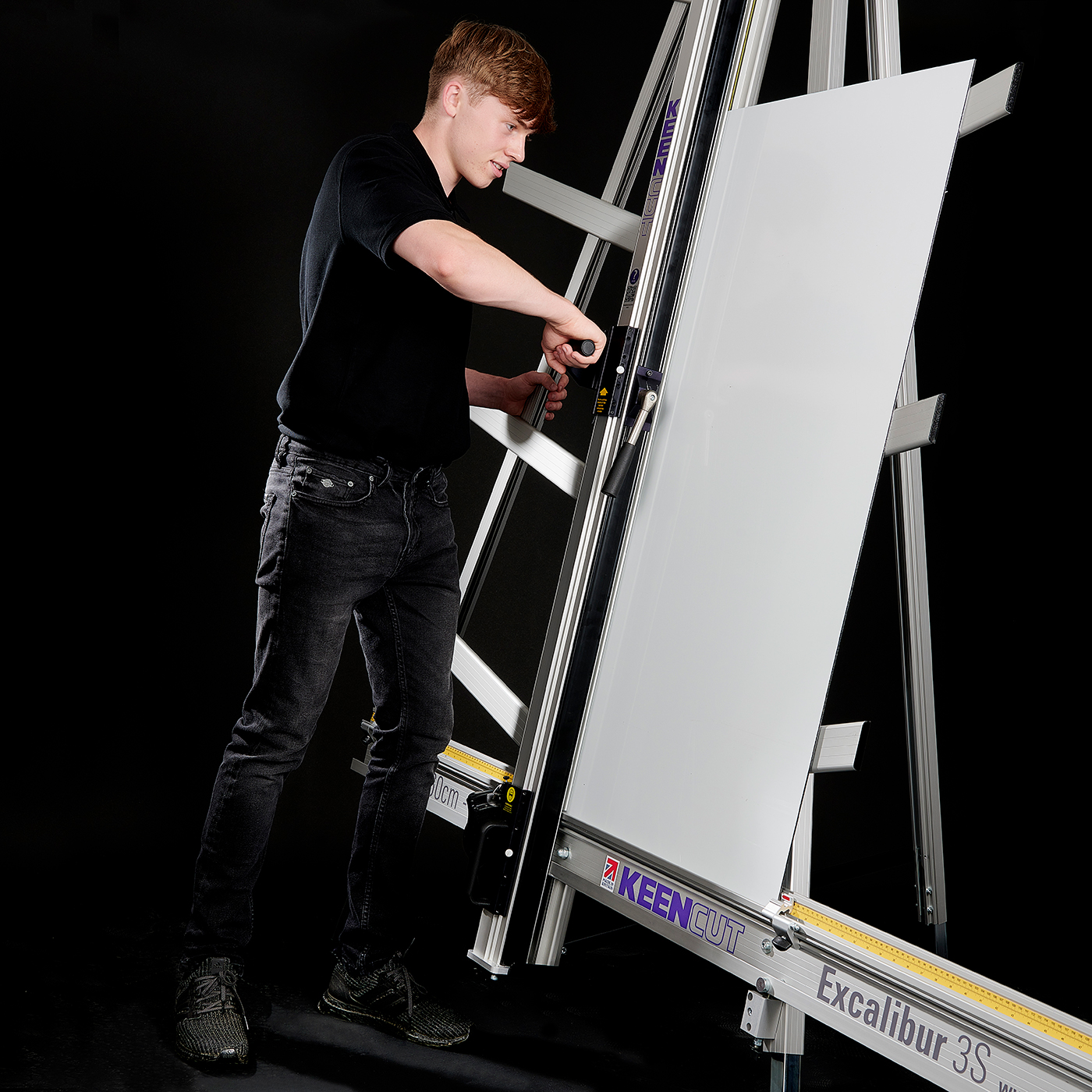
You will need approximately 1 hour to install and calibrate your cutter
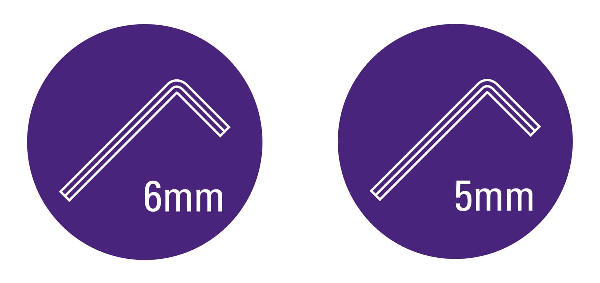
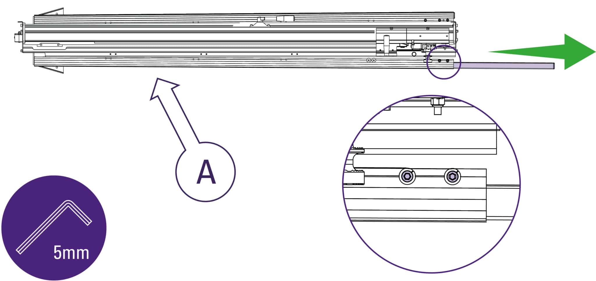
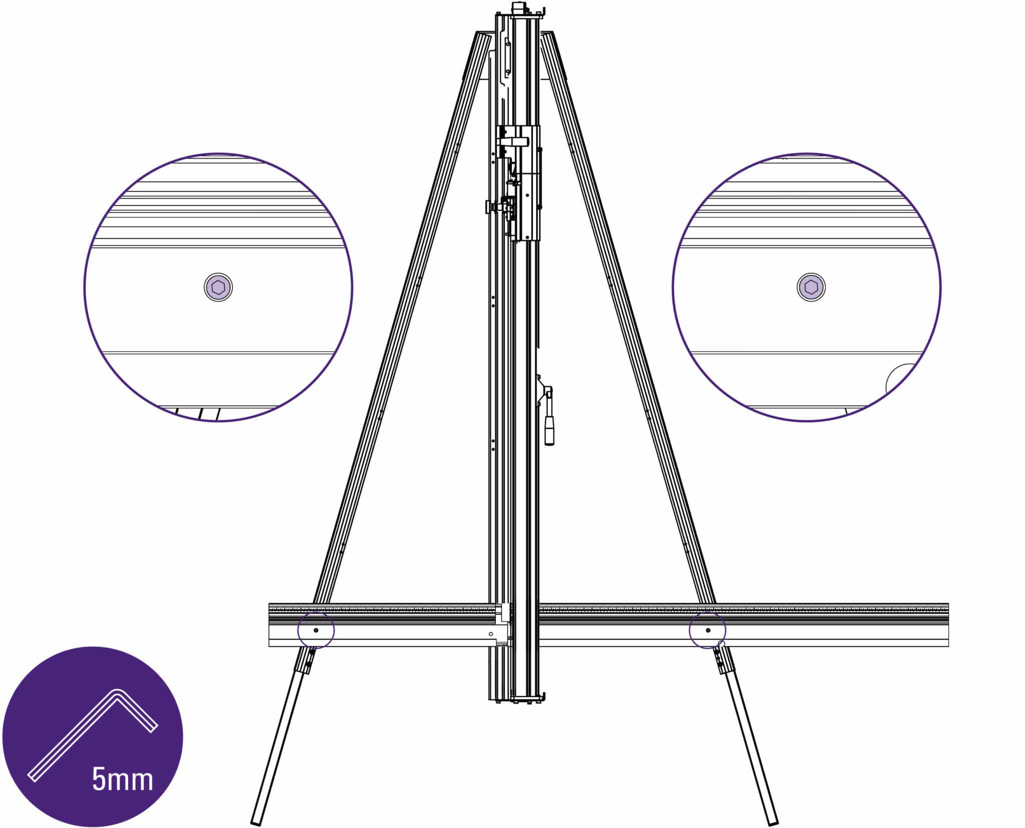
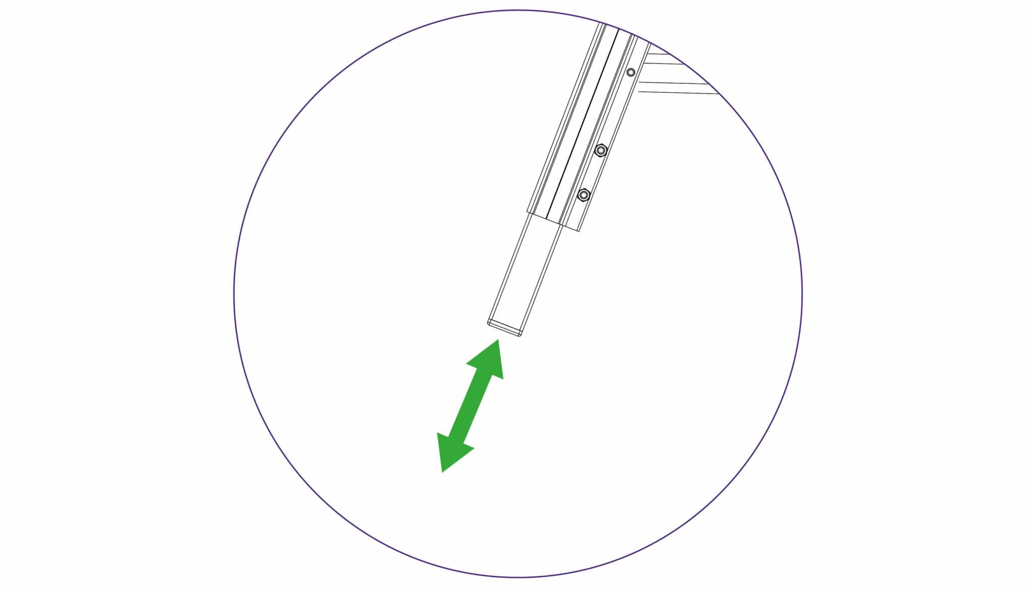
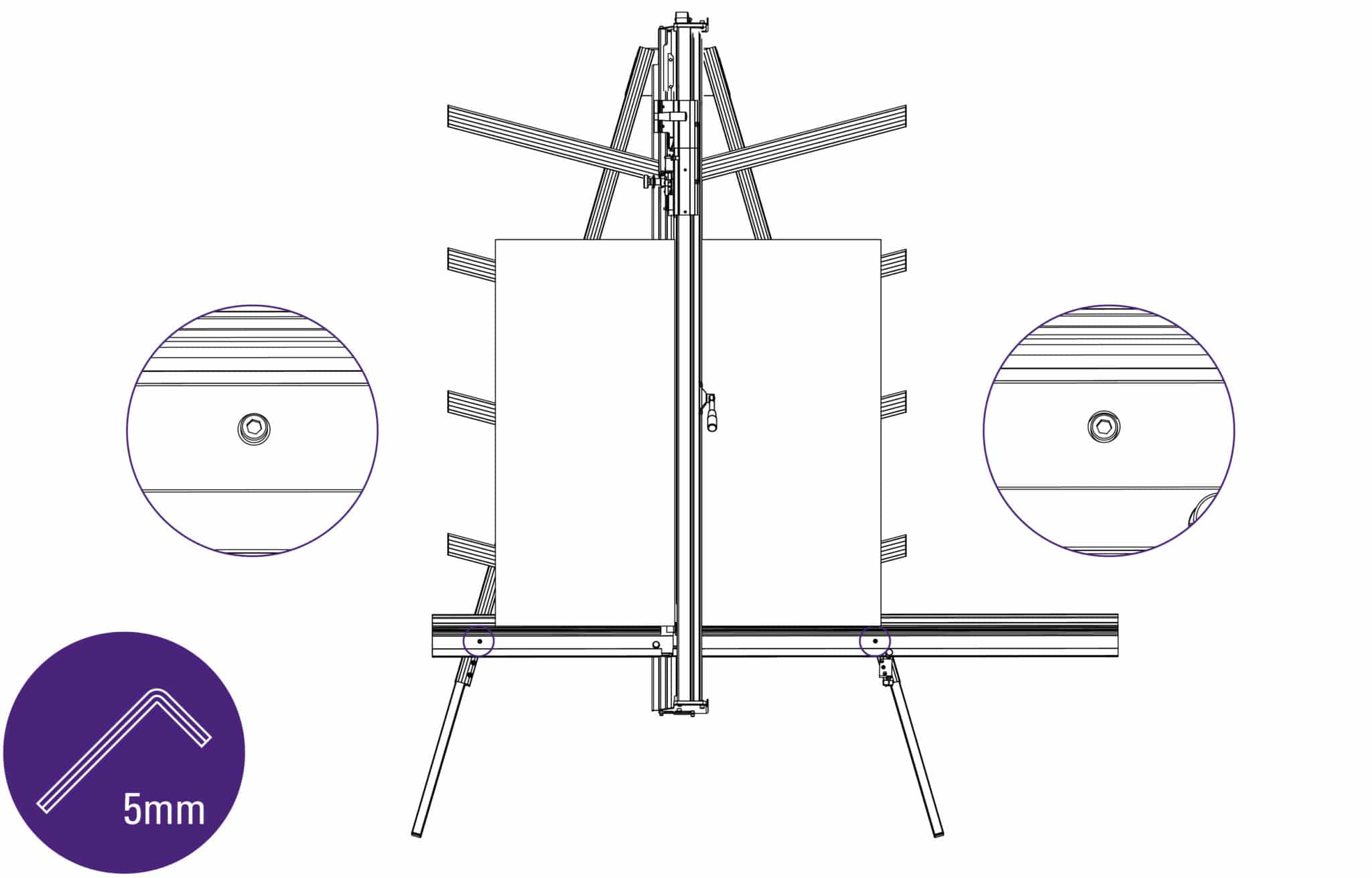
Slacken the bottom two screws on each leg using the 5mm Allen (hex) key and extend the
telescopic parts to the desired length. (These can be re-adjusted later before fixing the
machine to the wall). Tighten screws firmly to clamp in position.
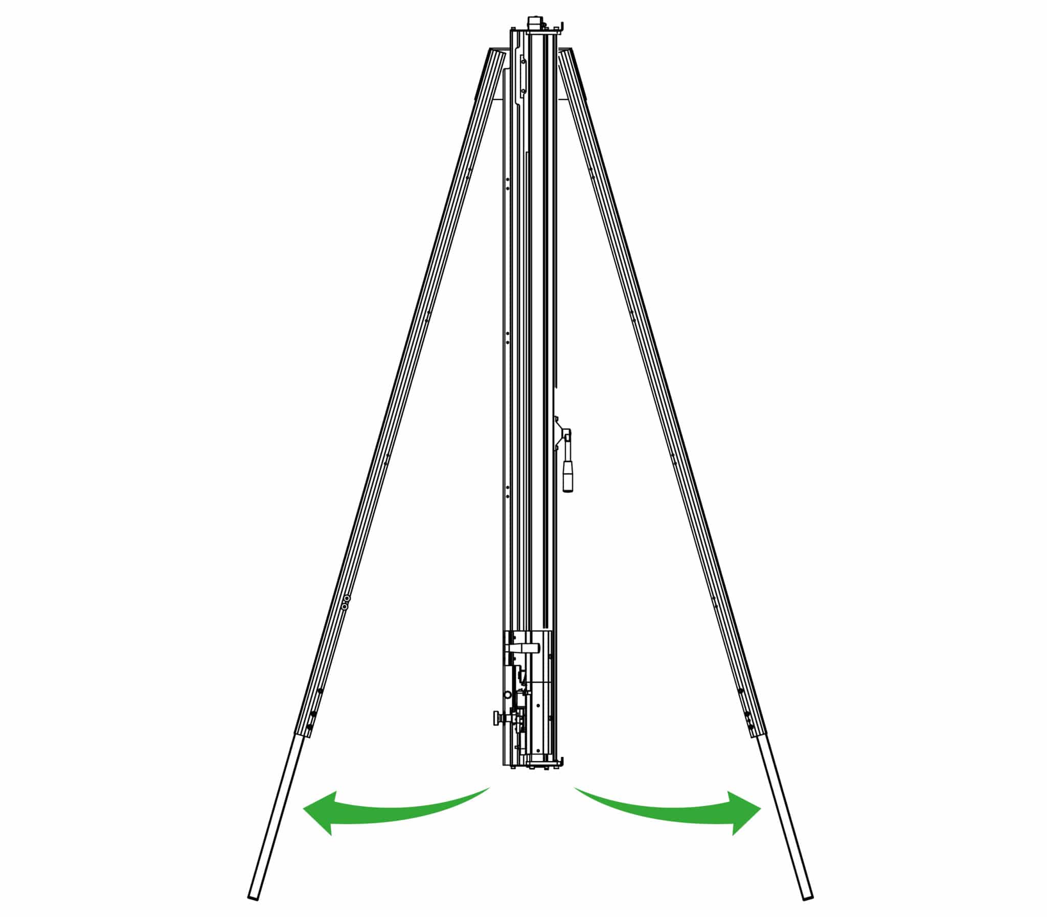
Swing both legs outwards as far as they will go.
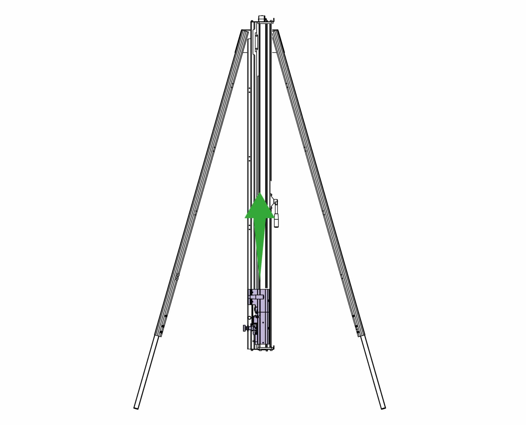
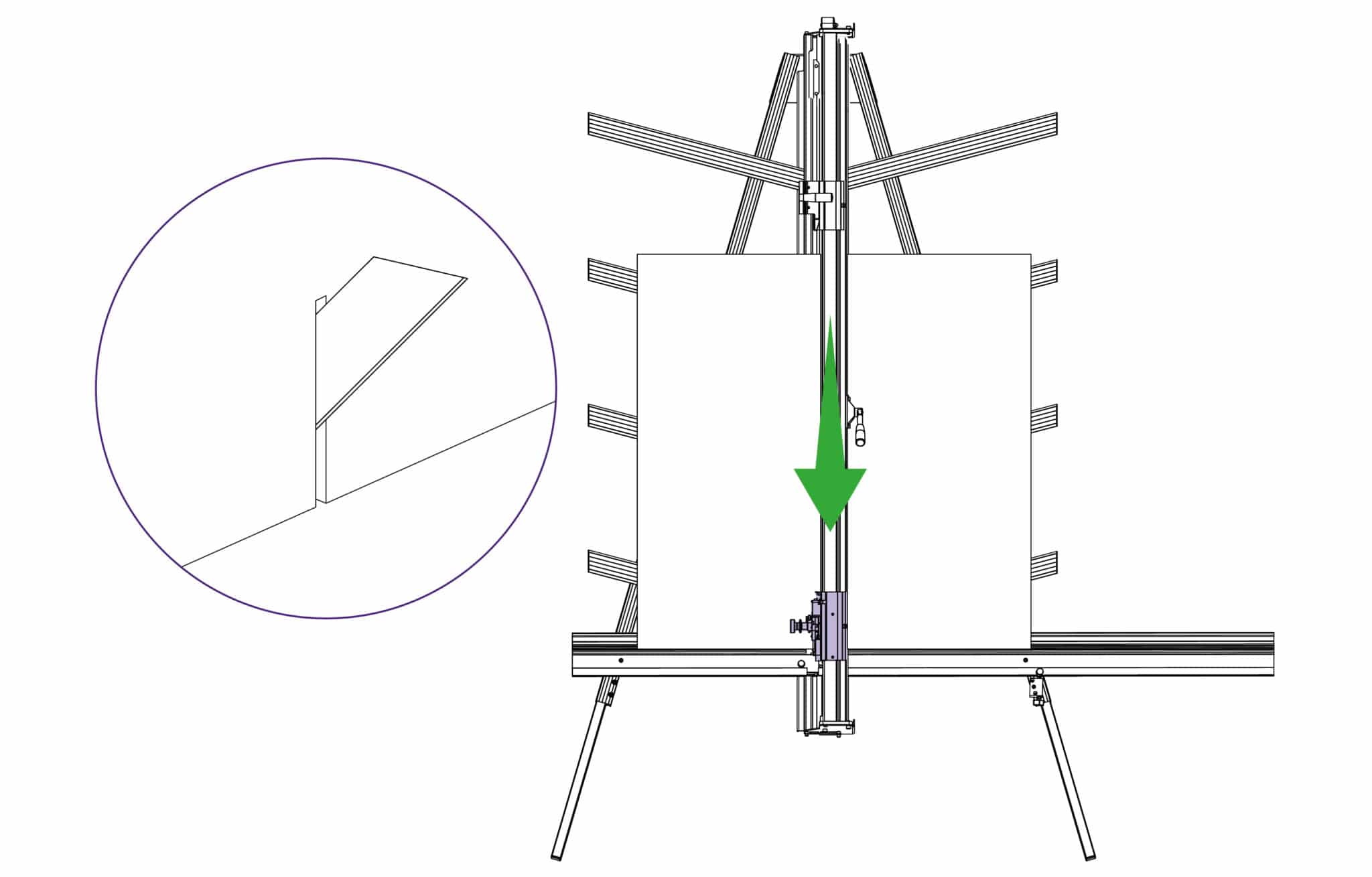
Move the lower cutting head to the middle of the main body.
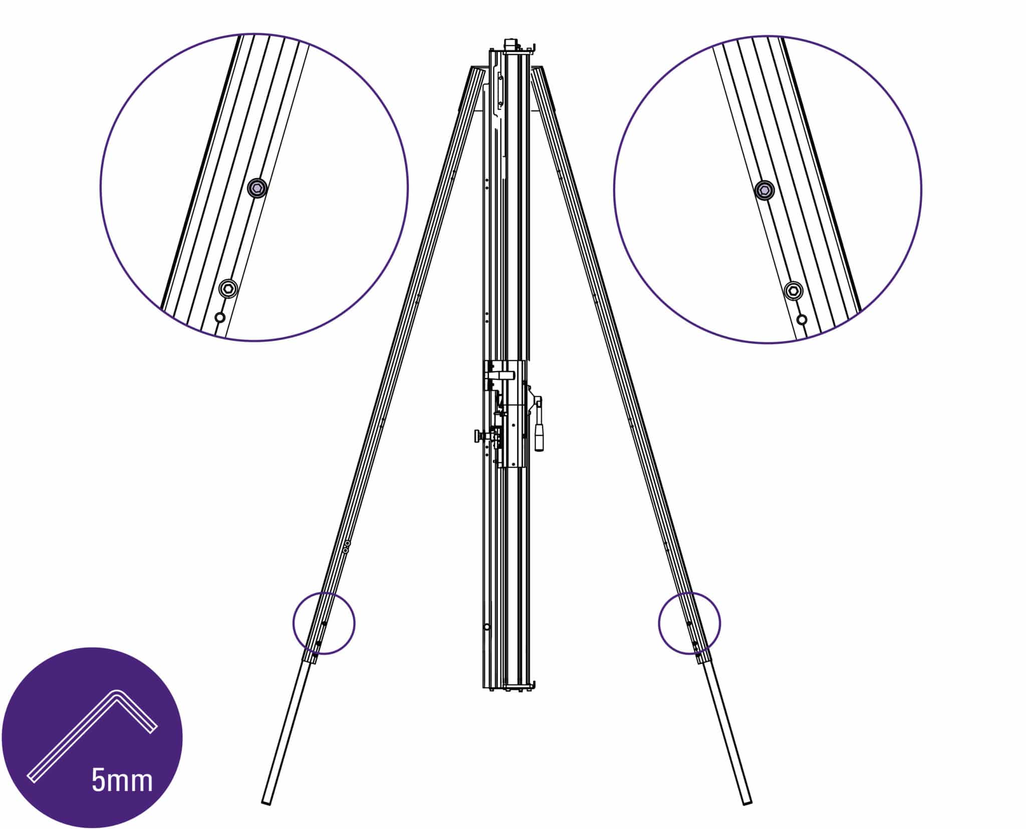
Remove one screw from each leg, using 5mm Allen (hex) key.
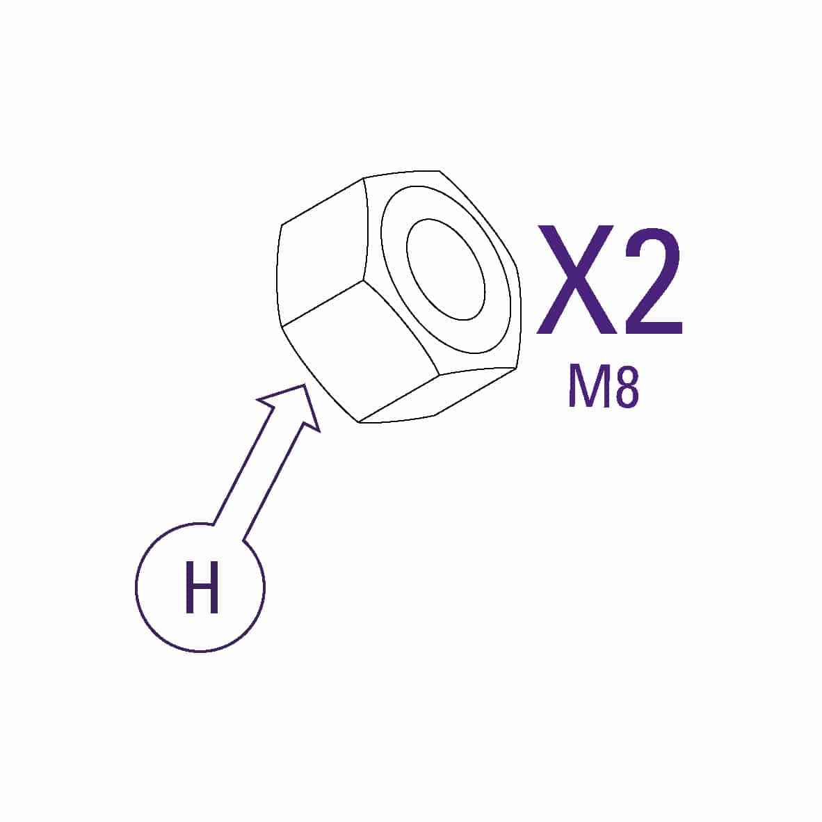
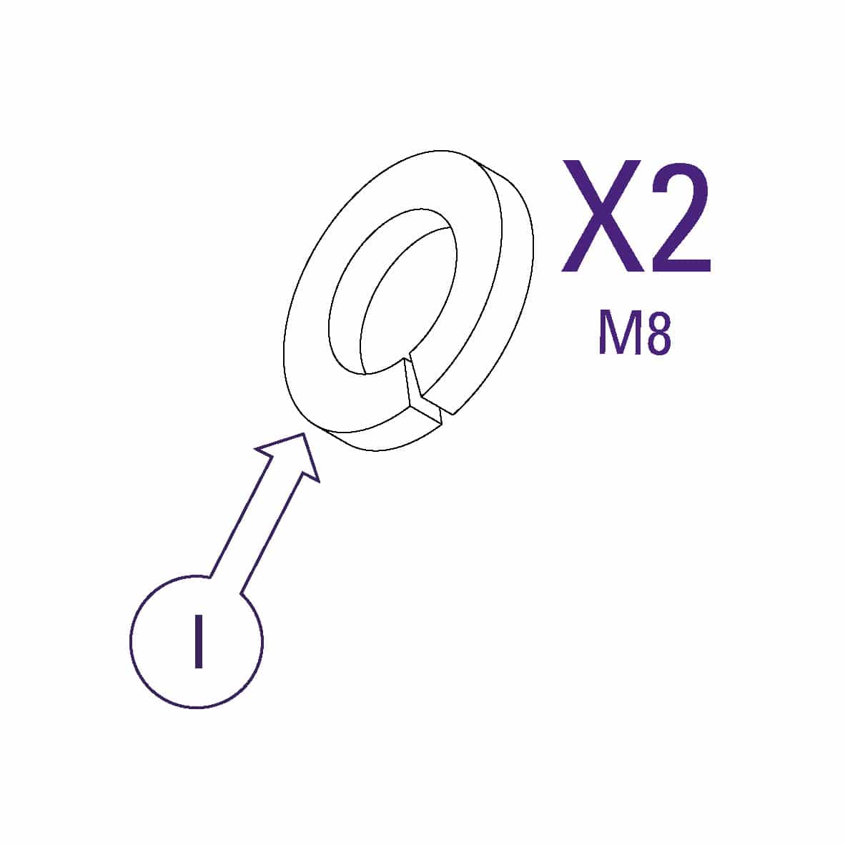
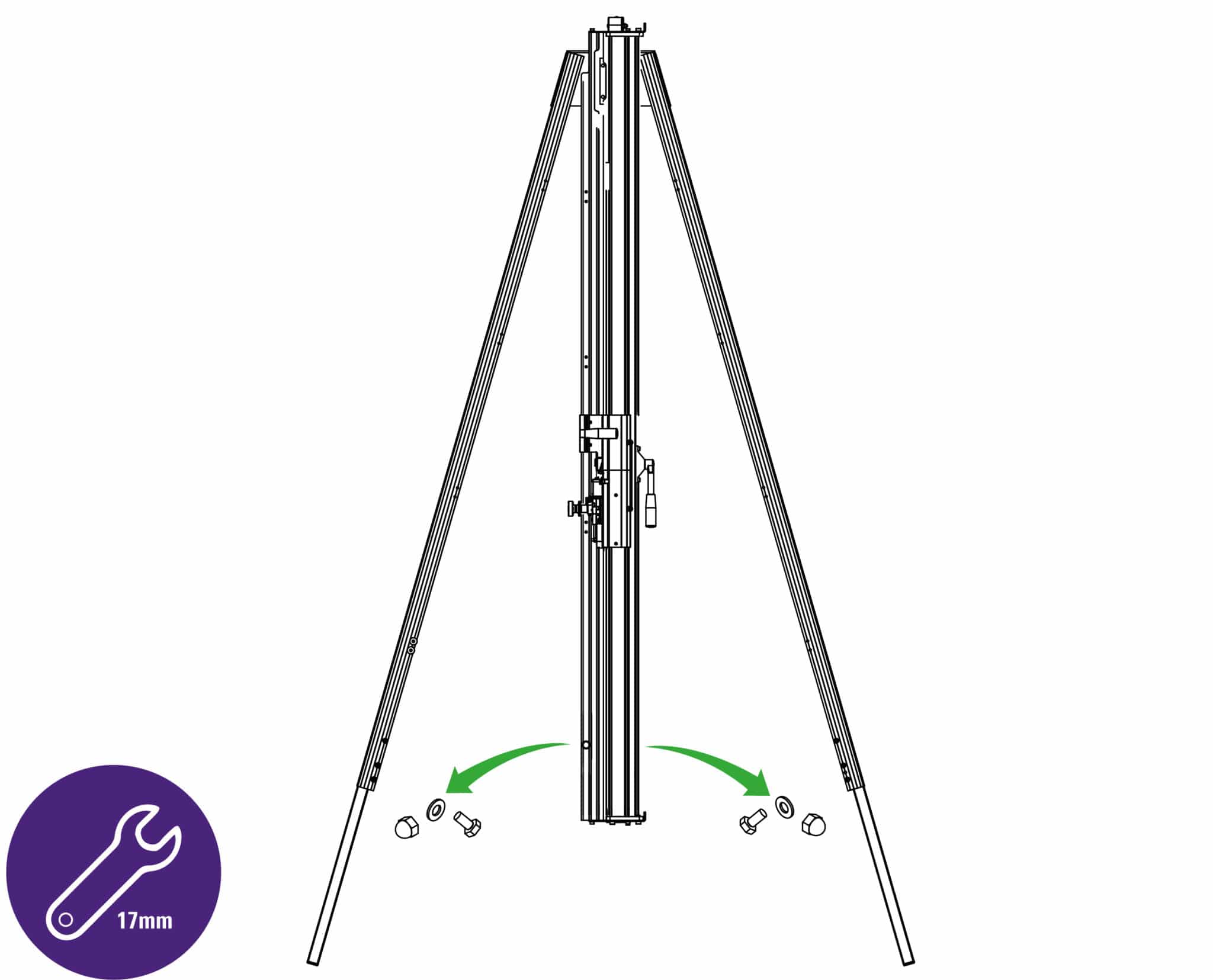
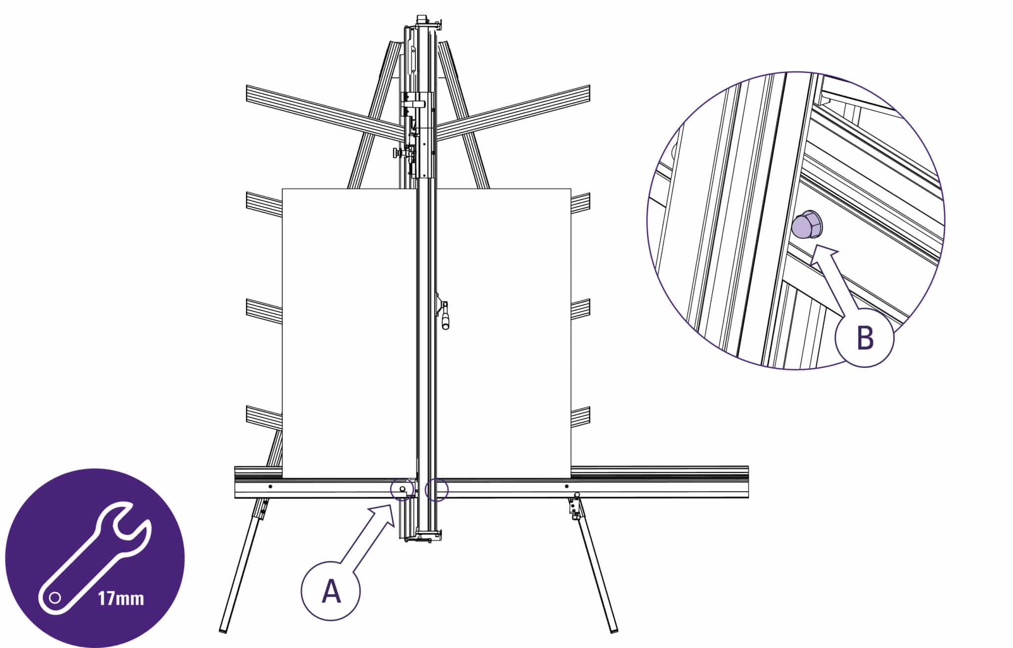
Remove two sets of hexagon headed bolts, washers and nuts from the main body using 17mm spanners.
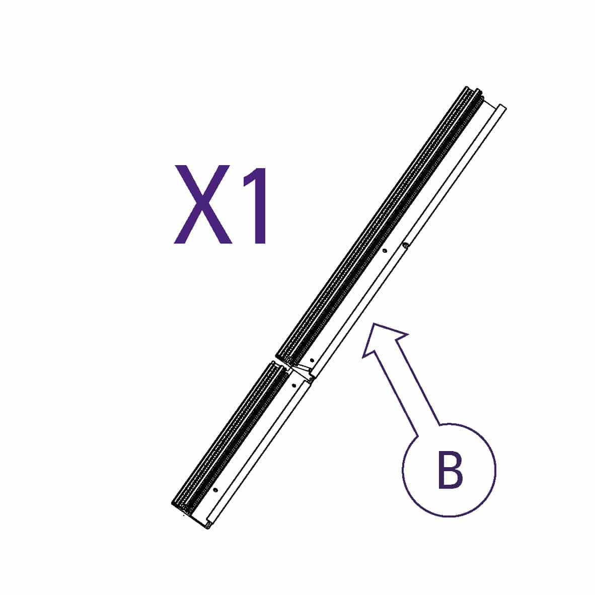
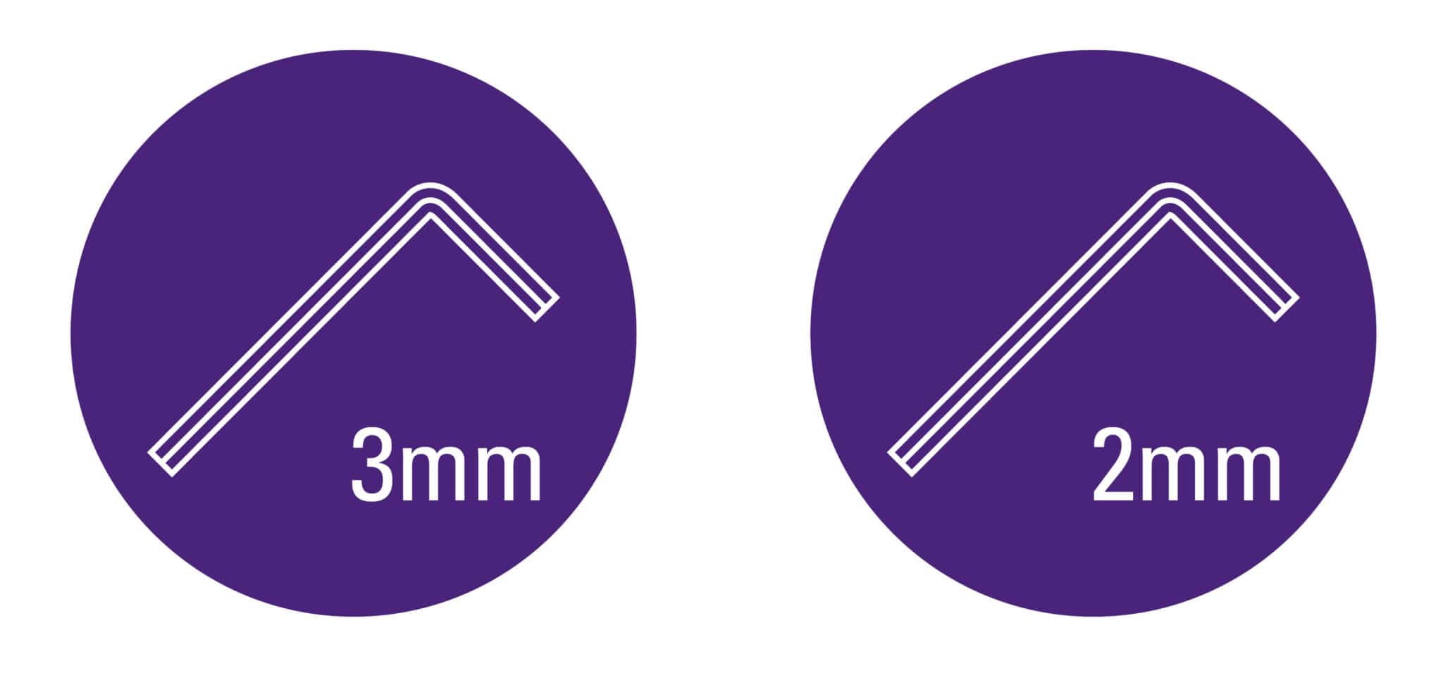
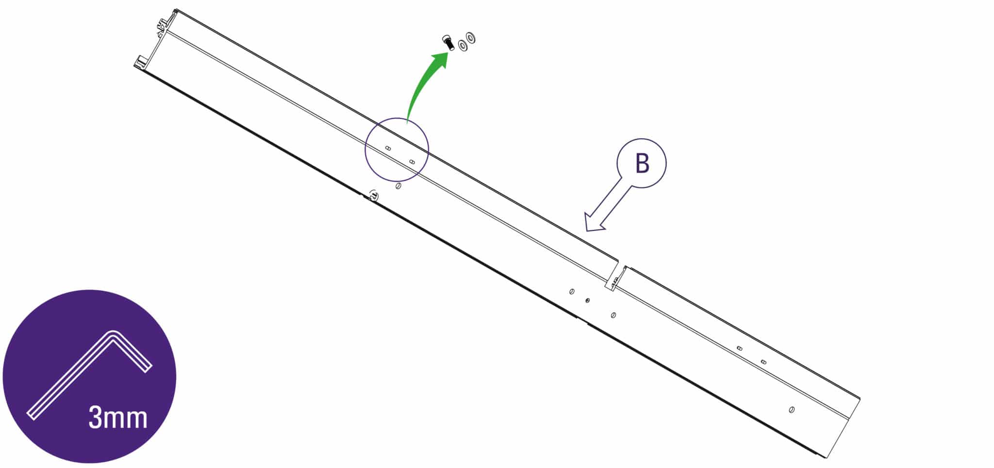
Remove small screw and two washers from the back of the squaring arm (part B)using the 3mm Allen (hex) key. (Right hand side ONLY).
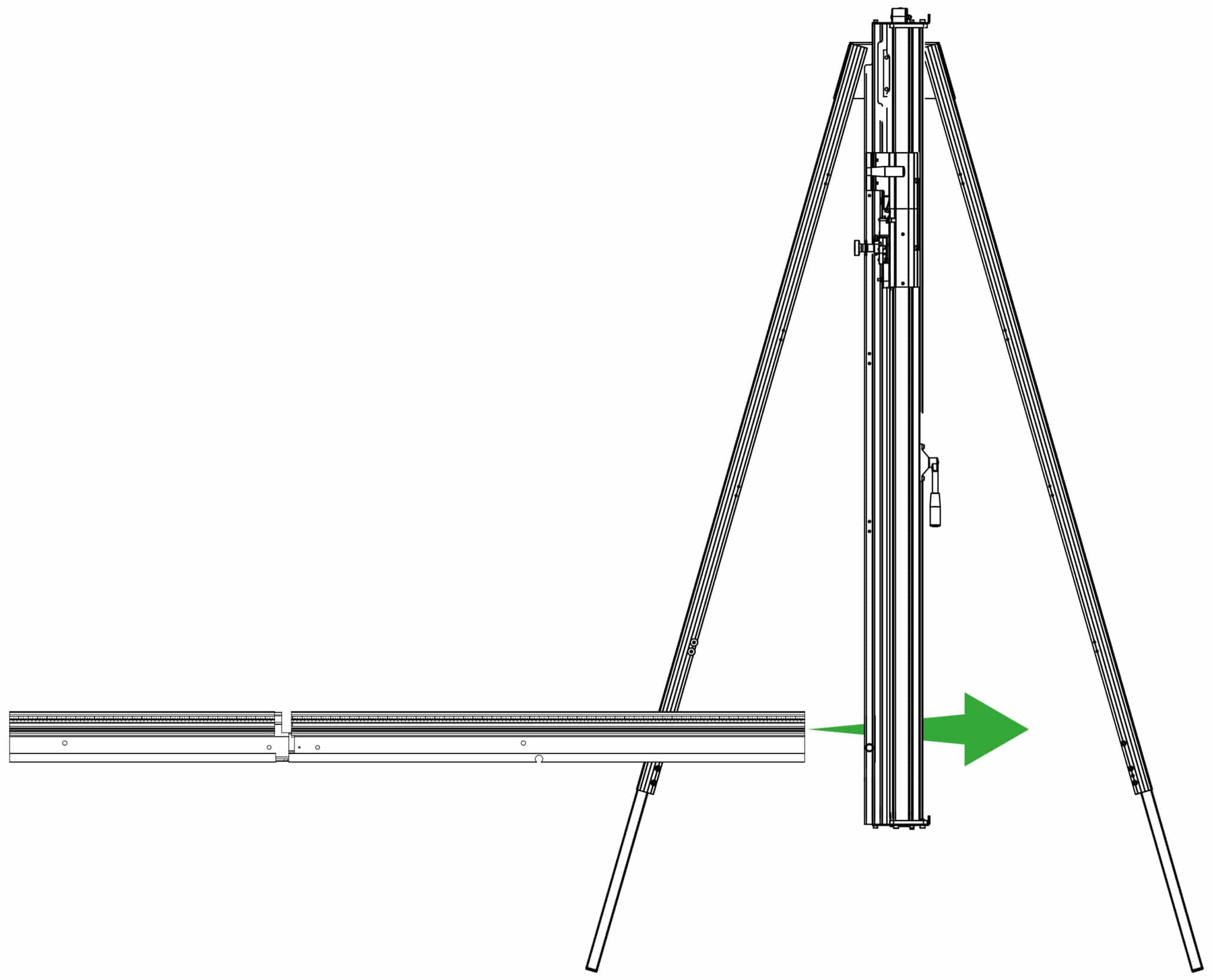
Slide the squaring arm in from the left hand side through the gap in the main body and align the corresponding screw holes.
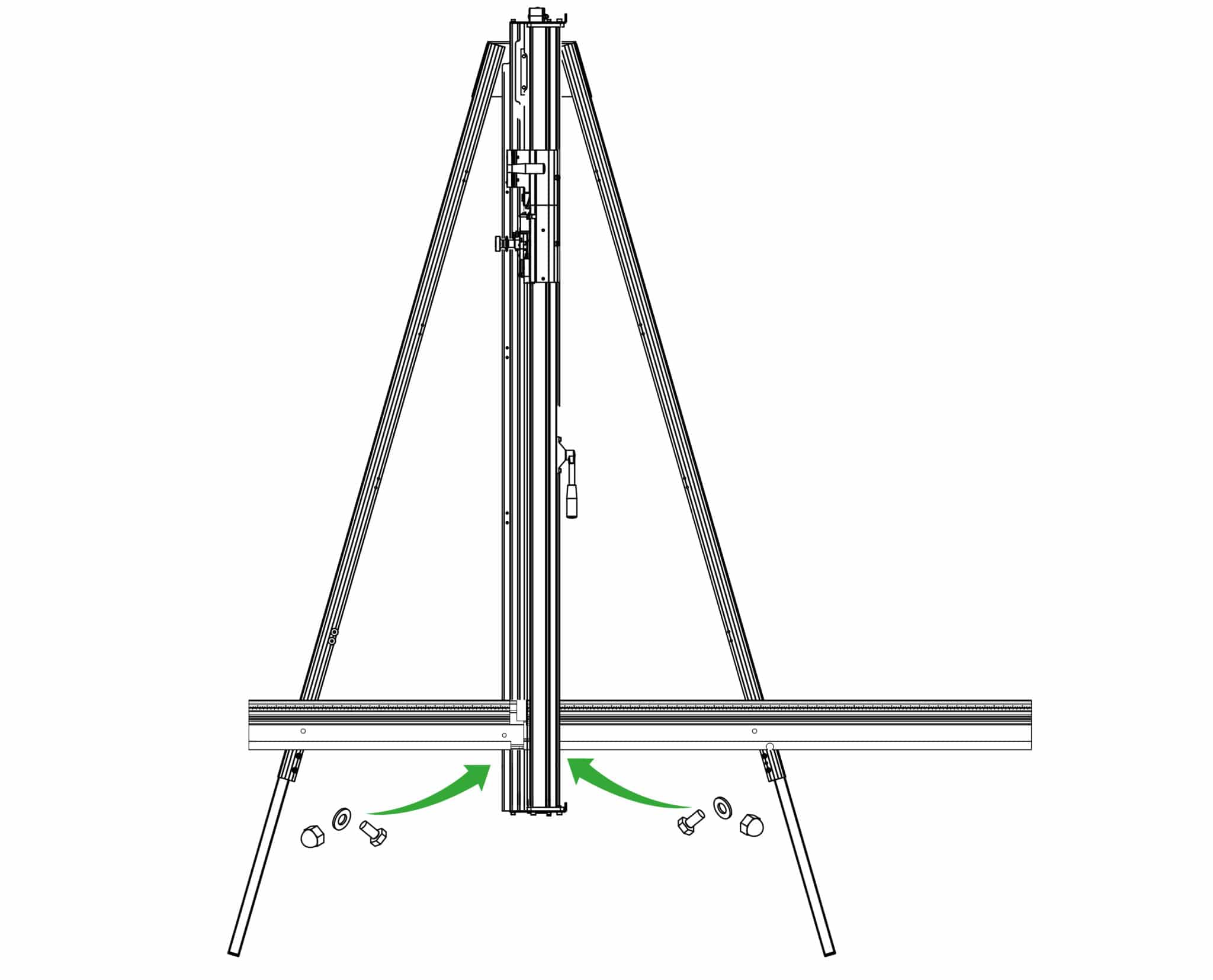
Fit the two hexagon bolts from the back of the main body, fit the washers and nuts finger tight only.
| Do this gently |
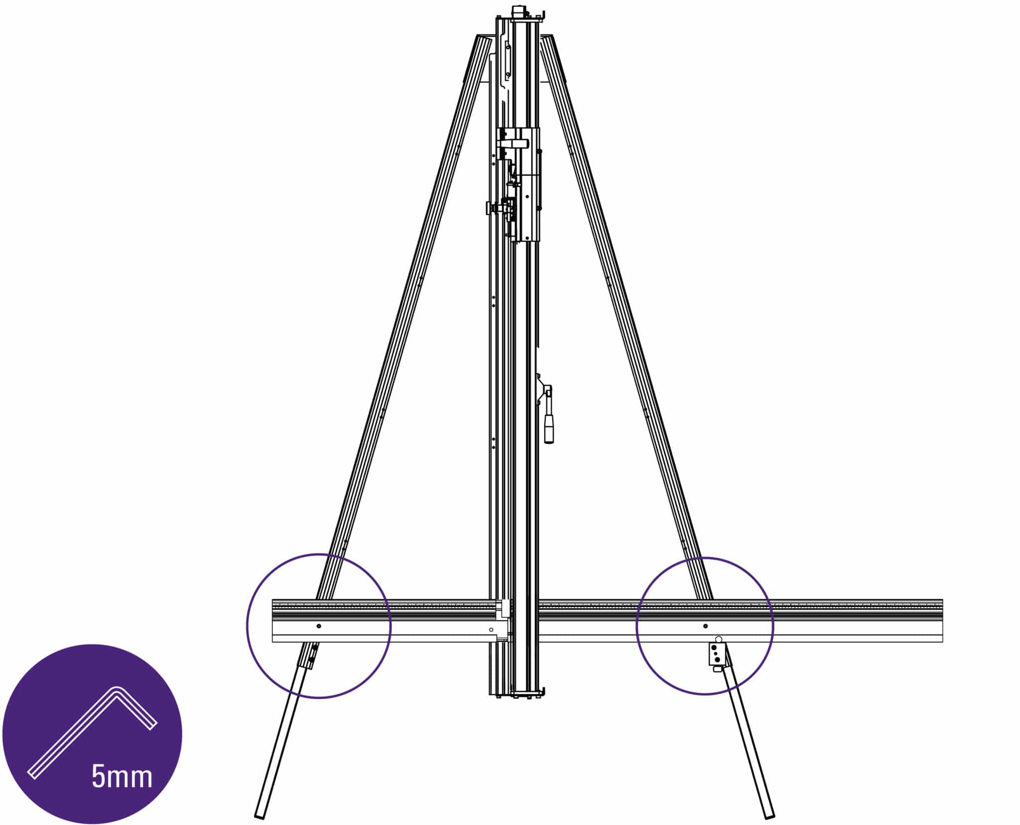
Fit the screws through the squaring arm into the leg using the 5mm Allen (hex) key, do not tighten fully.
| Do this gently |
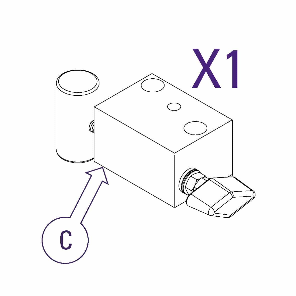
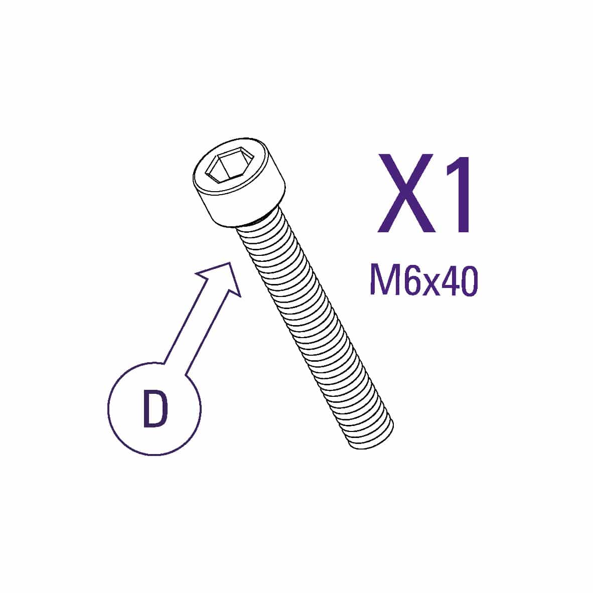
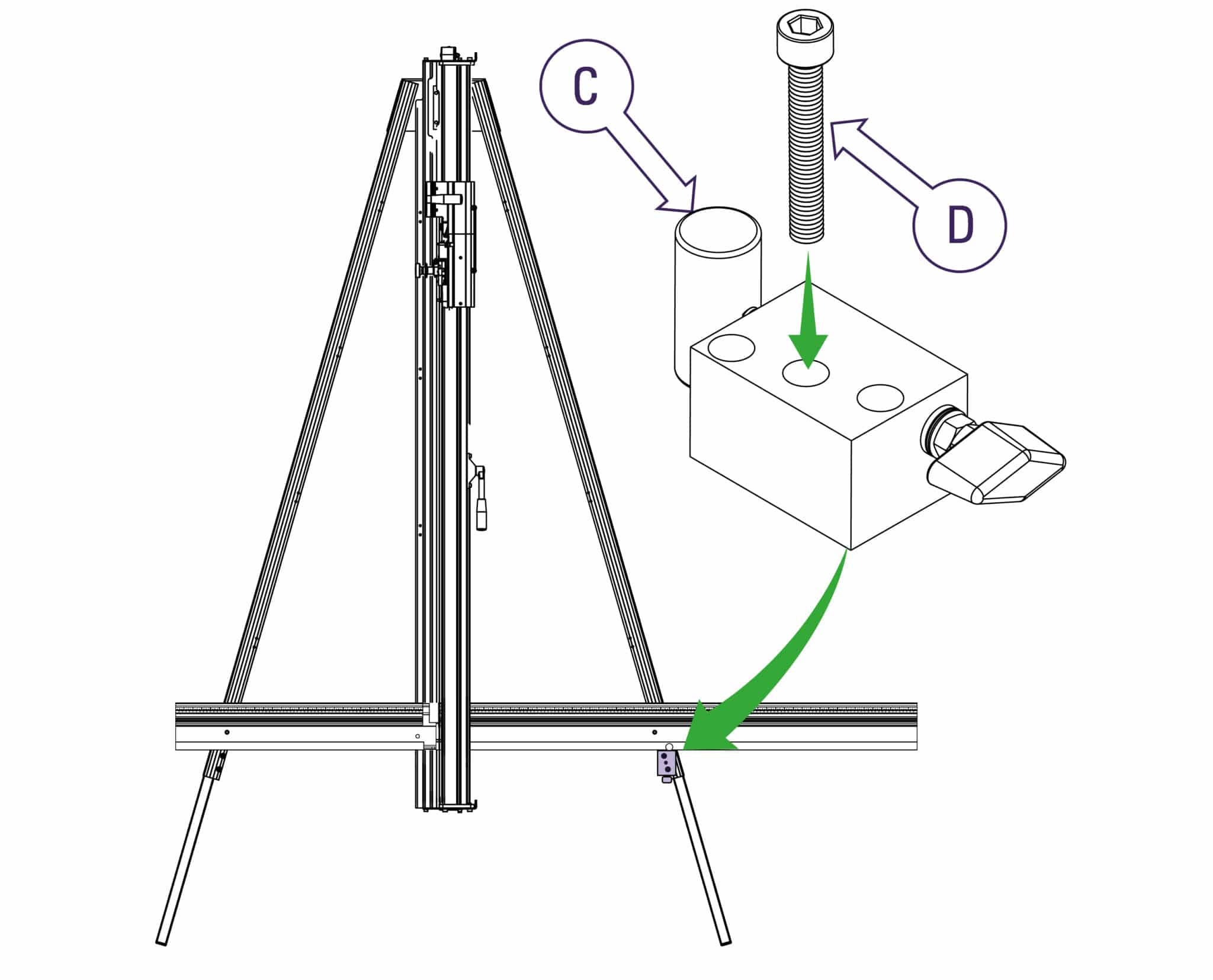
Refit the squaring adjuster block by firstly sliding the steel bar into the opening in the squaring arm, then align the heads of the two screws in the leg to fit the top and bottom holes in the adjuster block. The screws fixing the squaring arm to the machine should still be loose and allow it some movement to help alignment. Insert and tighten the screw (Part D) in the middle hole.
Tighten the two hexagon bolts and two screws.
| Do this firmly |
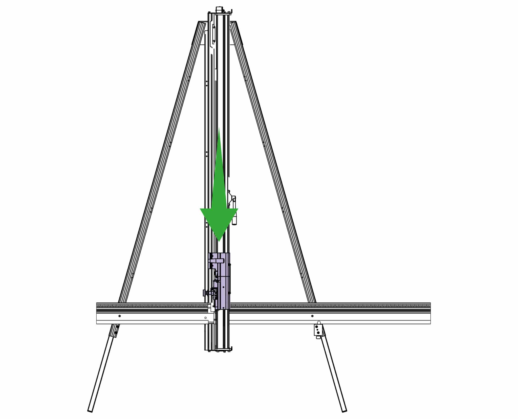
Untie and release the balance weight cord, ensure the clamp is closed by pushing down on the clamp handle then slide both cutting heads to the bottom.
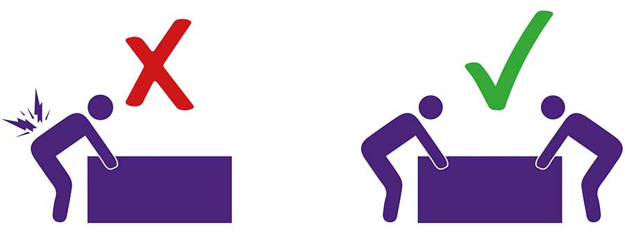
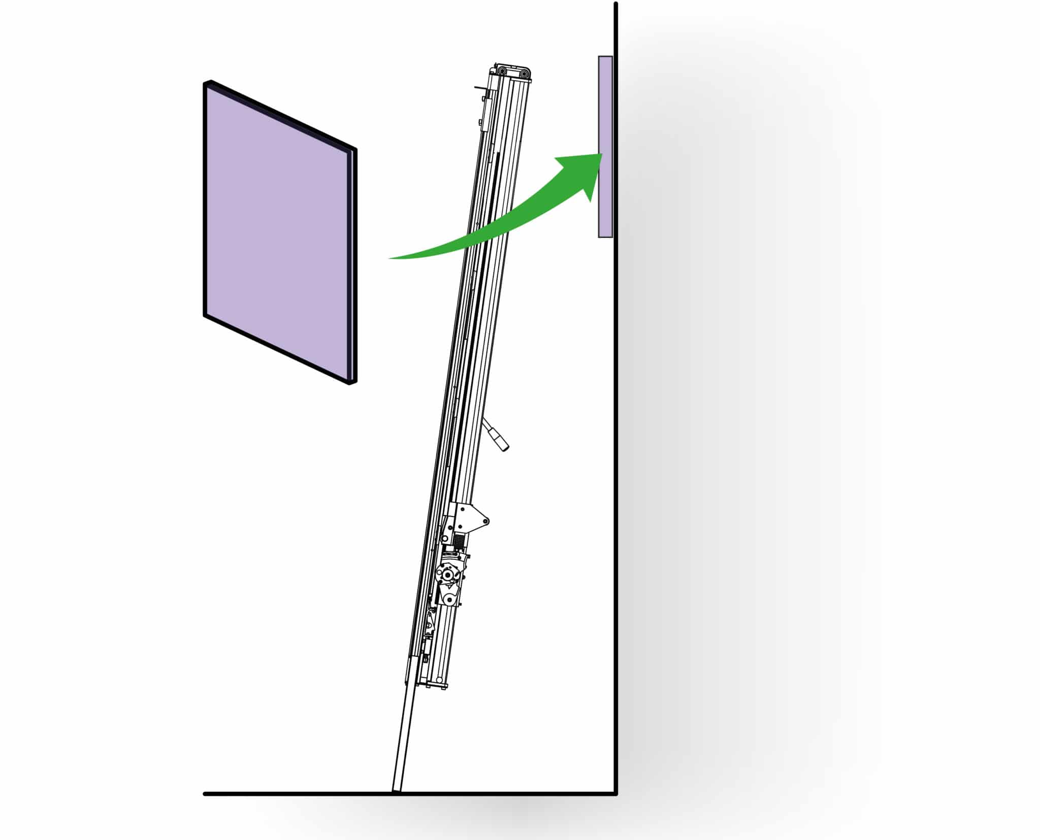
Get help to slowly lift the machine and lean it so the front faces towards the wall. Carefully place a scrap of card or board between the top end of the machine and the wall to prevent any damage.
| Be careful when lifting |
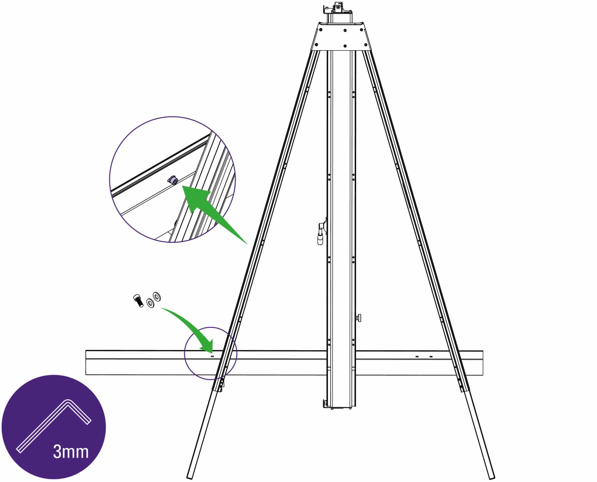
Replace the screw and two washers in the squaring arm using the 3mm Allen (hex) key.
| Do this firmly |
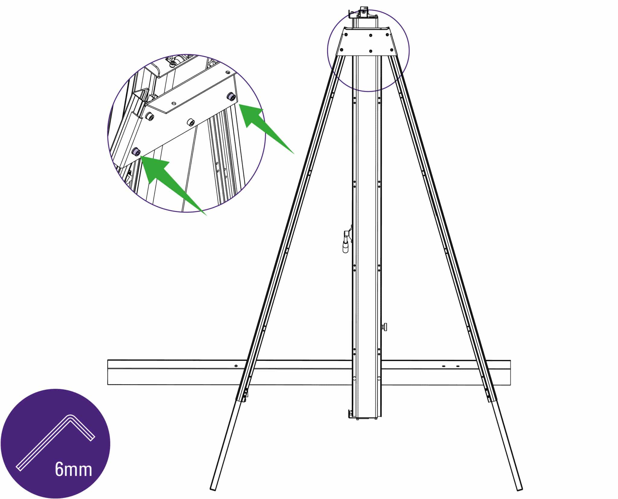
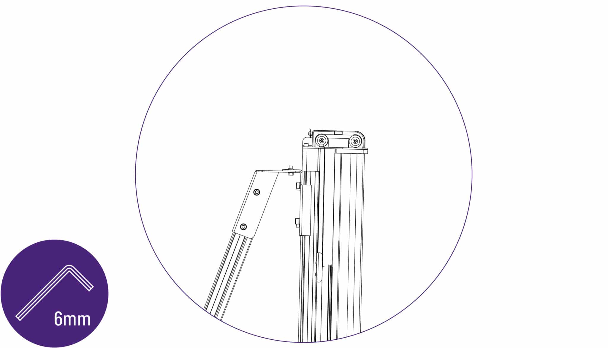
Fit the two screws to secure the legs at the top of the main body using the 6mm Allen (hex) key, tighten both screws fully. Tighten the other two adjacent screws.
| Do this firmly |
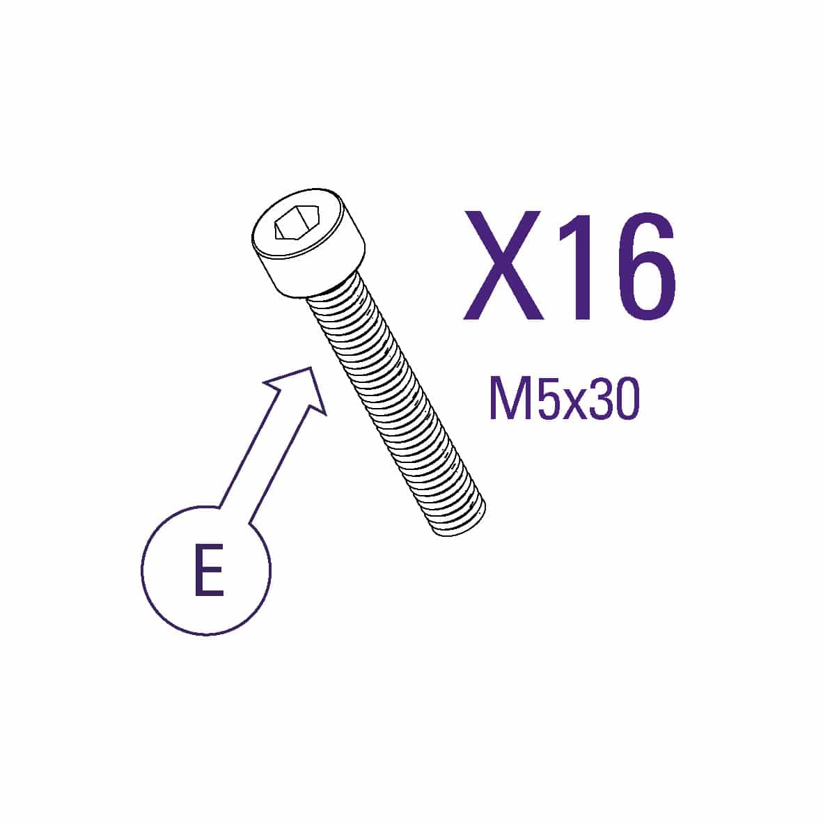
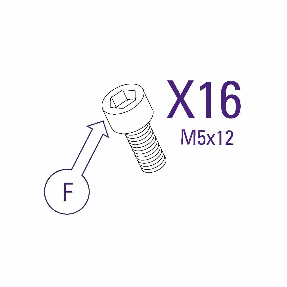
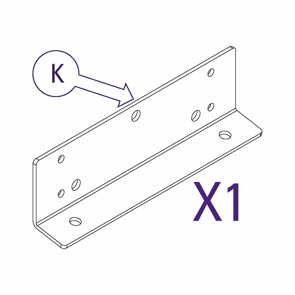
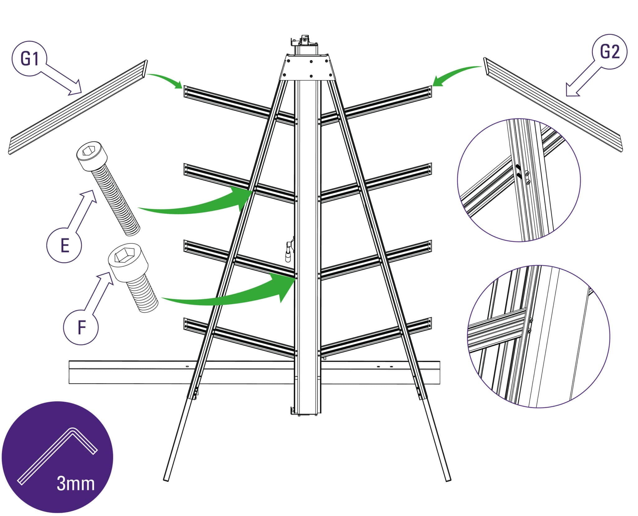
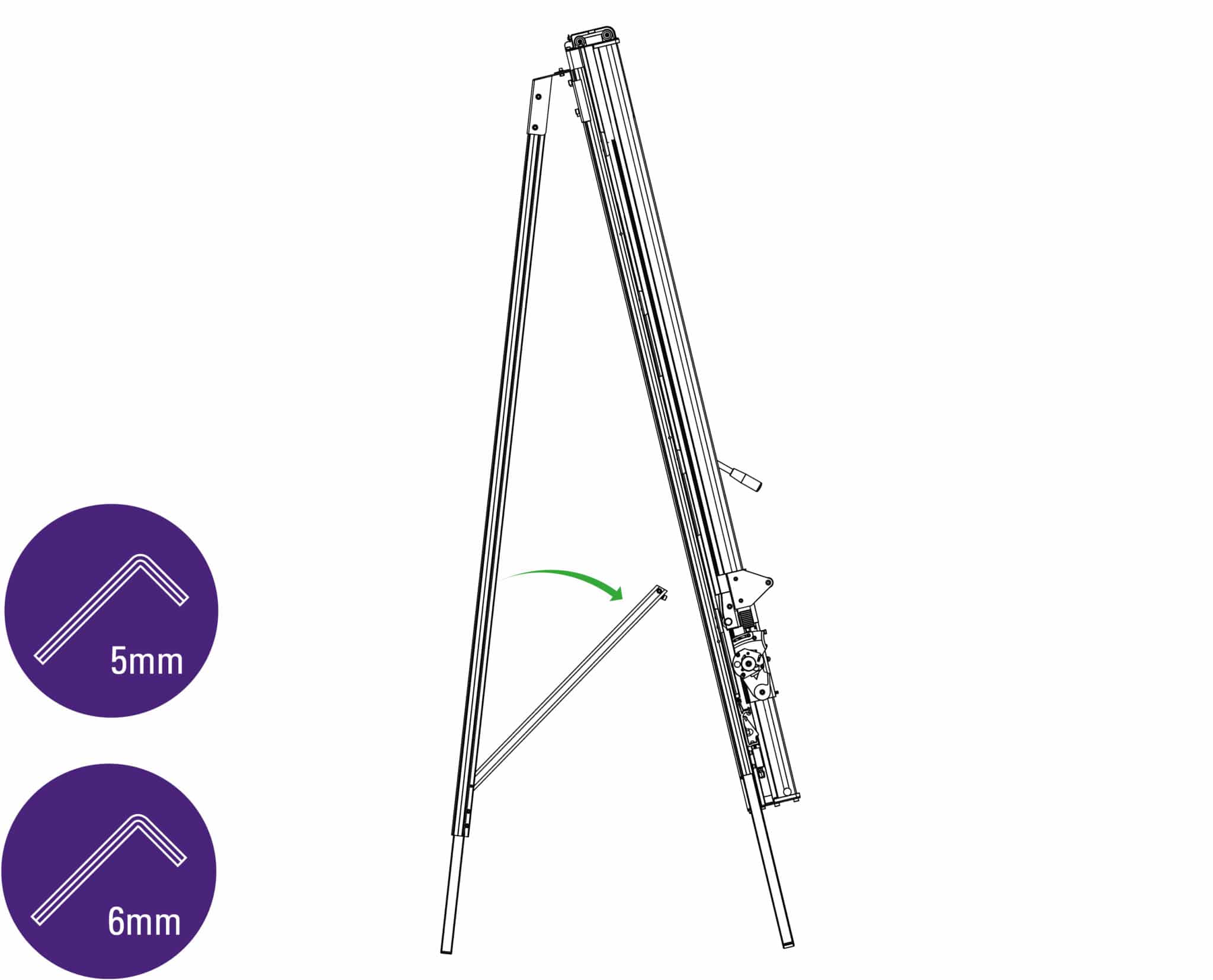
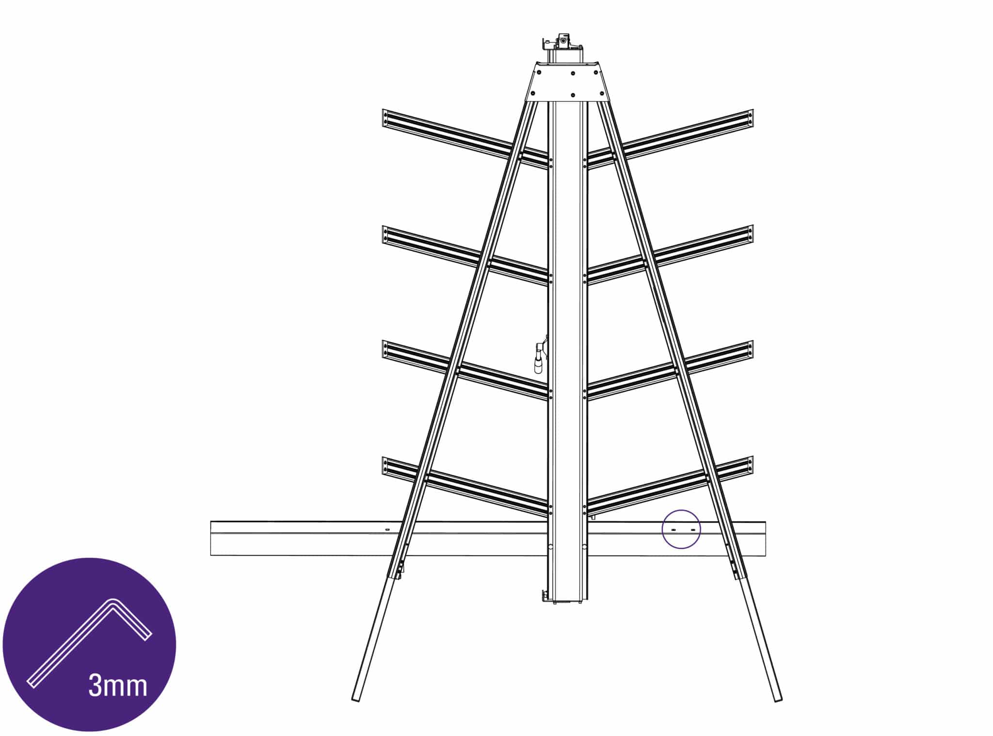
Use one of the long screws in each of the holes along the legs of the machine and short screws to fix the support arm to the main body. Ensure the ends of the supports are firmly against the main body and the screws are aligned with the special grooves as explained above.
If a free standing kit is to be fitted to the machine proceed directly to Fitting the optional free standing kit >
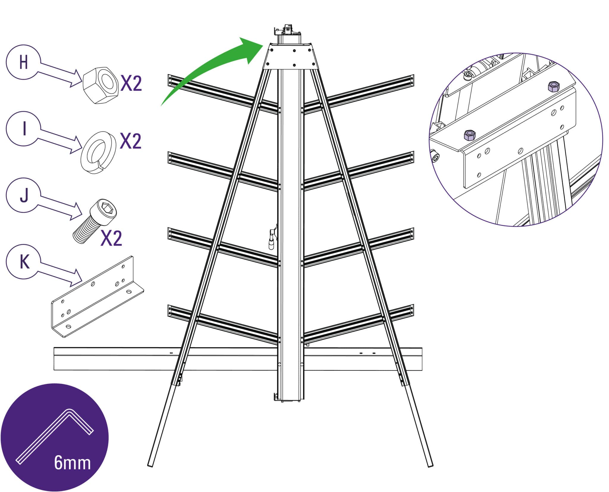
Fit the wall mounting bracket to the top of the main body, fasten the screws finger tight only.
| Do this gently |
If you are going to fit the free standing kit (optional) proceed to Fitting the optional free standing kit >
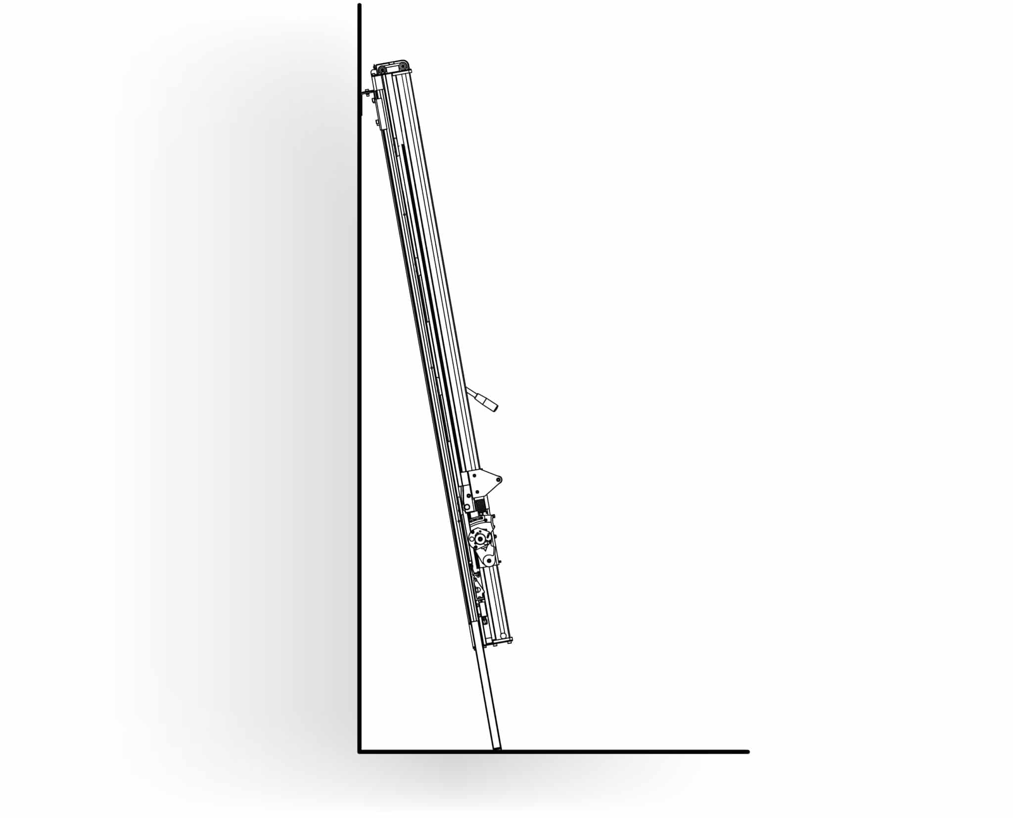
Stand the machine vertical and turn around so the machine is now facing away from the wall.
| Be careful when lifting |
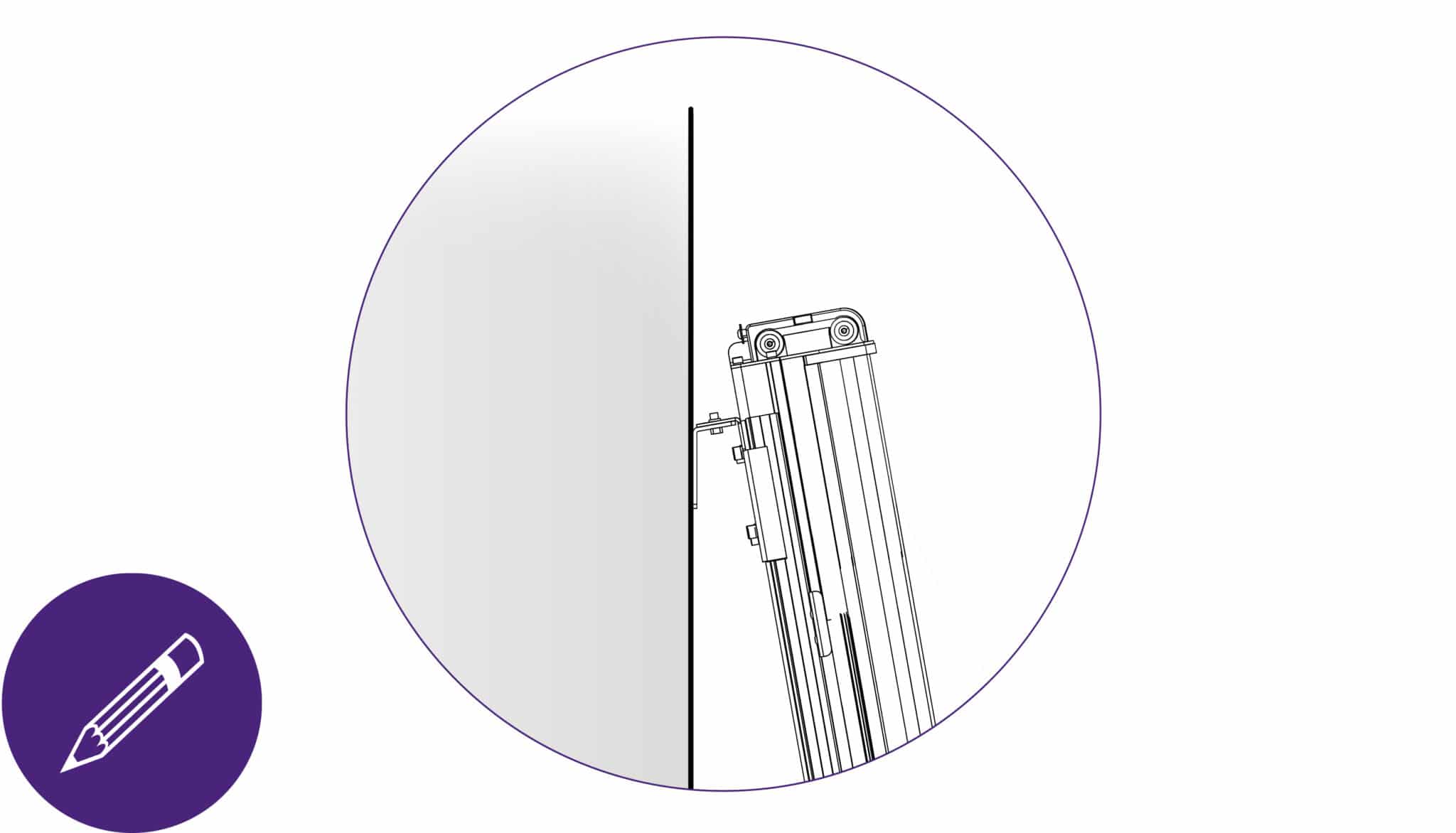
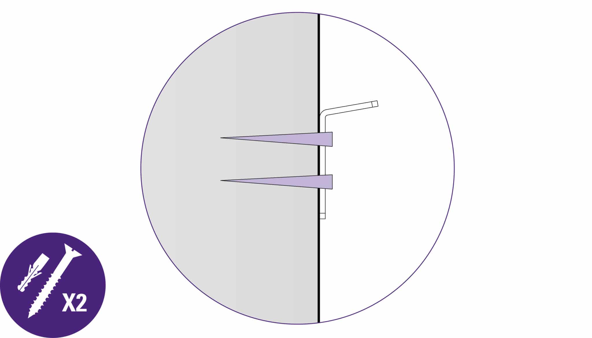
The wall mounting bracket should lay flush against the wall. Mark the position of the wall fixings with a short pencil.
Move the machine away and remove the wall mounting bracket.
| Be careful when lifting |
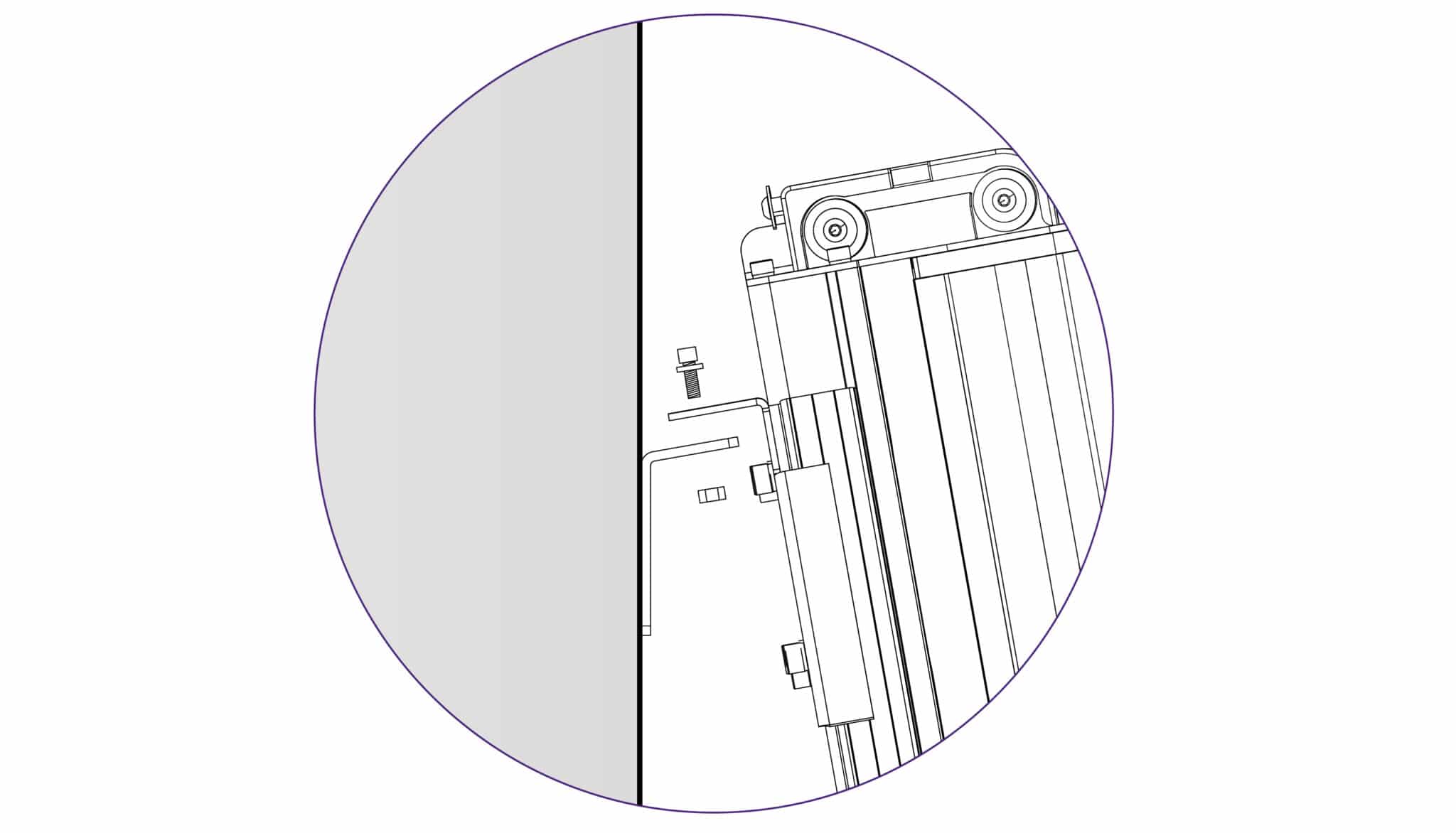
Attach the bracket to the wall in the marked position with appropriate fixings then reposition and fasten the machine to the bracket.
Proceed to Checking the machine for squareness >
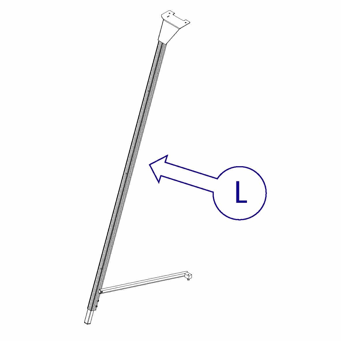
Extend the telescopic leg to the same length as the front legs less 12cm (5”).
Assistance will be needed for the following stages
Get help to stand the machine up and hold it while the free standing leg is fixed to the bracket using the 6mm Allen (hex) key (nuts and screws provided with the main machine)
| Do this firmly |
Swing down the stay and attach the fixing block to the back of the main body, tighten all three screws on the stay (using the 5mm & 6mm Allen (hex) keys).
Extend the telescopic leg so the machine stands evenly.
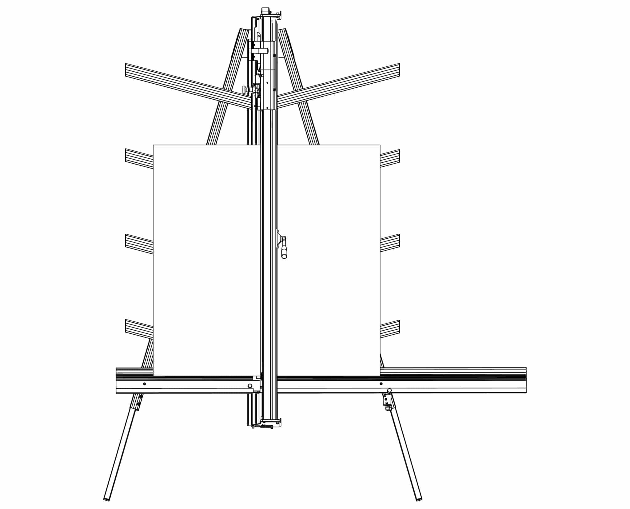
Place the board on the machine vertically as shown and apply the clamp ensuring the bottom edge is in firm contact with the squaring arm.
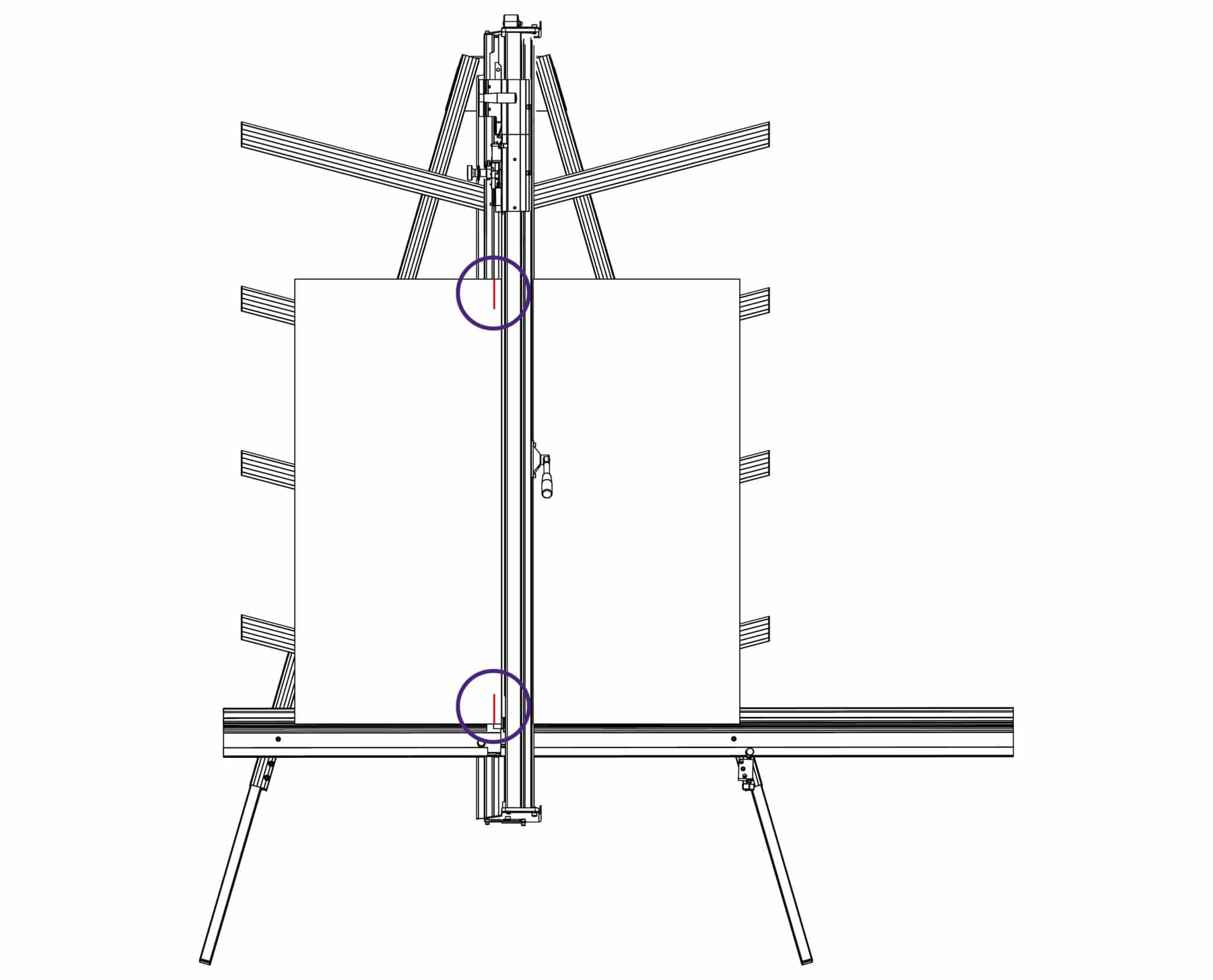
Select the cutting blade on the lower cutting head (see Using the multi-tool cutter head & counterbalance >). Cut into the top board to produce a cut approximately 3cm (1”) long. Disengage the cutter using the cutter release lever. Lower the cutter and make a similar cut at the bottom of the board.
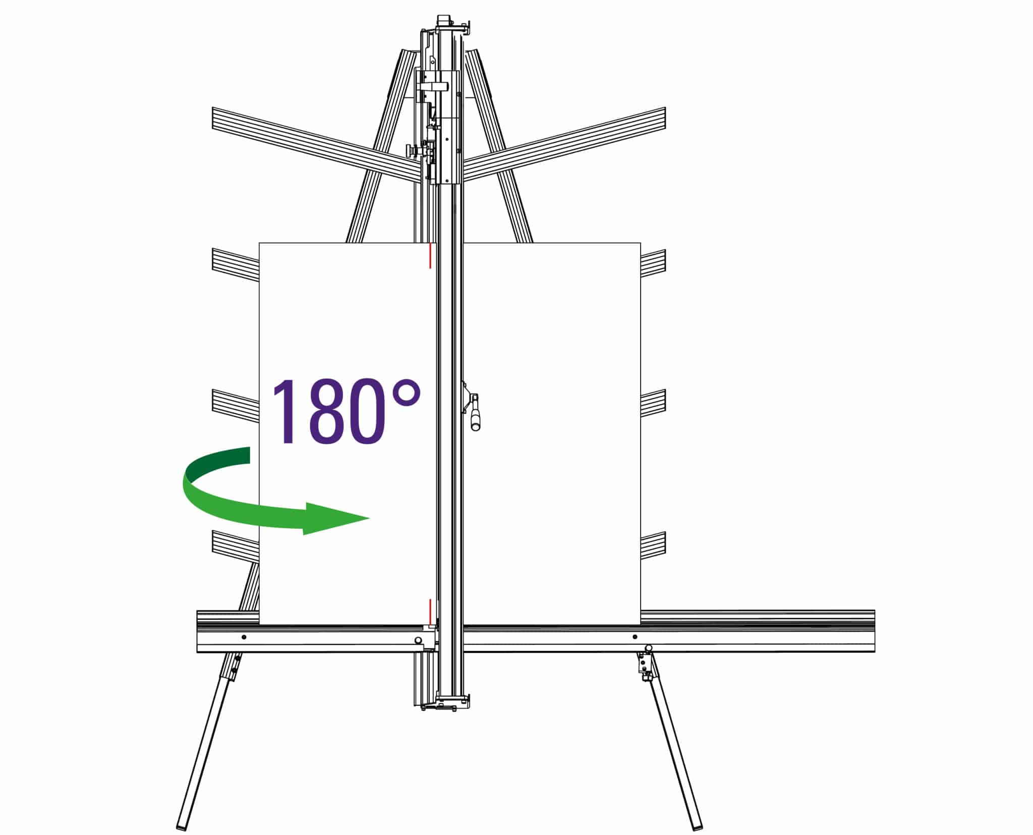
Unclamp and turn the board around (like the page in a book) and place it back in the machine so the same edge is still on the squaring arm but do not clamp it. Align and engage the blade so it enters the previous made cut at the bottom edge of the board. Now apply the clamp.
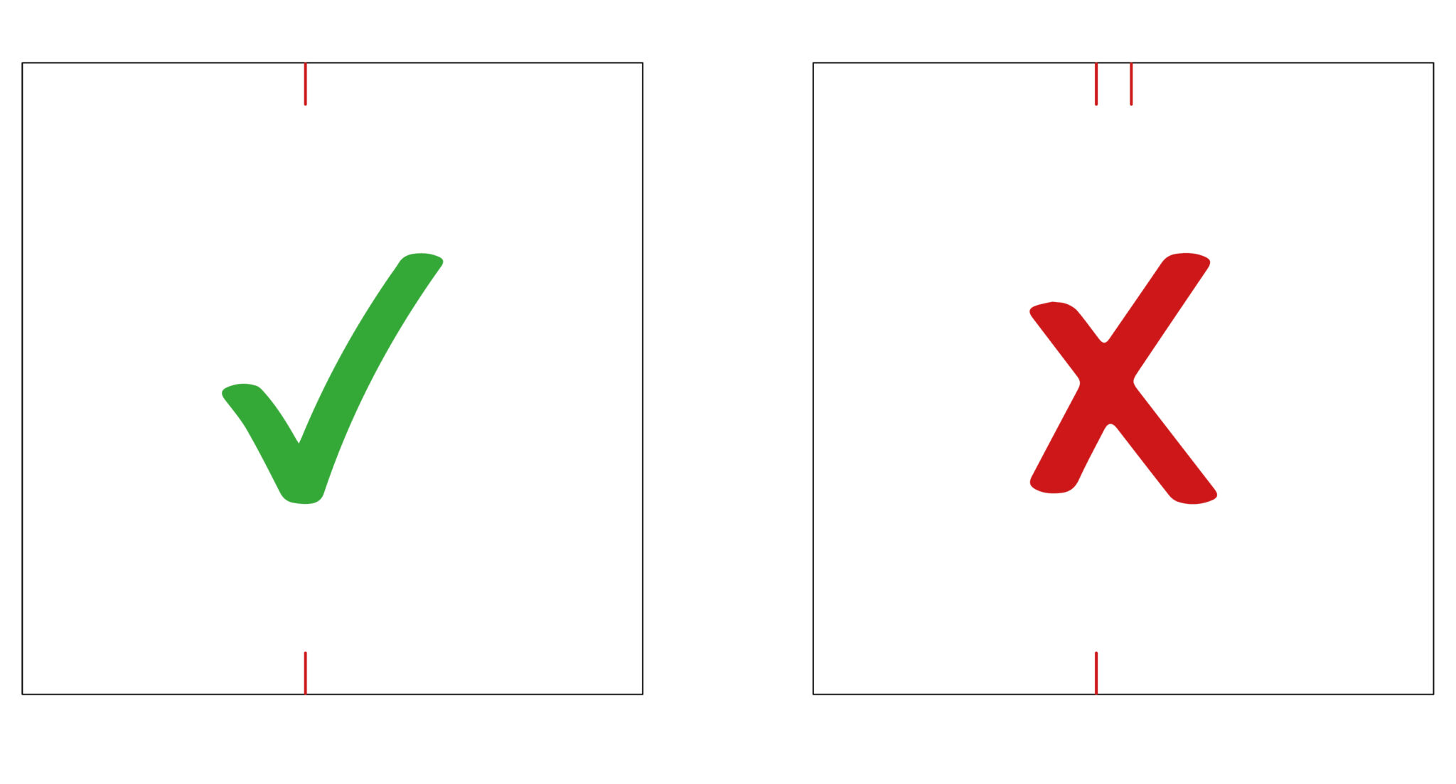
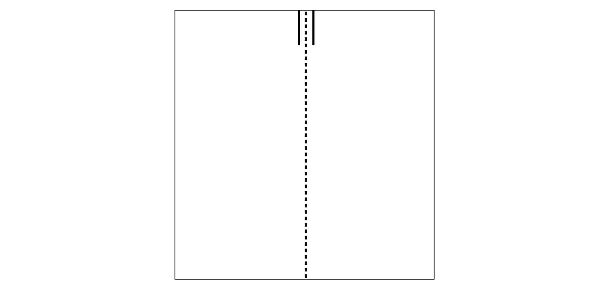
Raise the cutter to the top of the board, if the machine is square the blade should enter
the same cut as made previously. If not refer to Adjusting the squareness> to make the necessary
adjustment.
If it is square, continue to Calibrating the vertical scale>
NOTE: Before making any adjustments carry out the squareness check as described in Checking the machine for squareness>
It is assumed that the board used for the test is still clamped in the machine. From the test results determine if the last cut made in the top of the board is to the left or right of the previous cut.
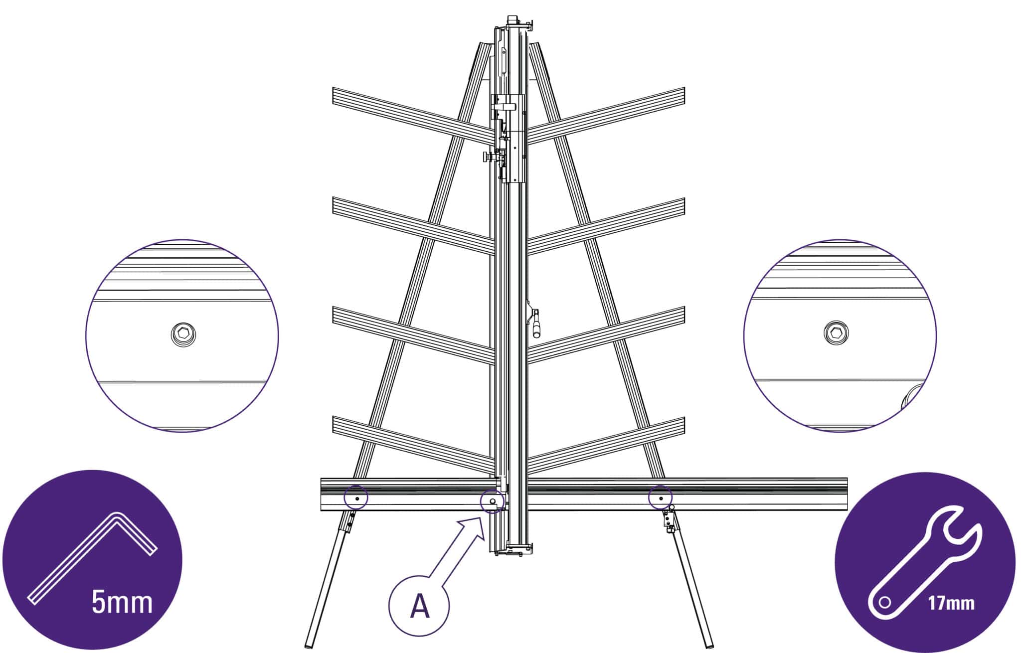
Use a 5mm Allen (Hex) key to slacken the two screws joining the squaring arm to the two legs.
Use a 17mm spanner to slacken the left hand nut (A) joining the squaring arm to the main body, make sure the right hand nut (B) is tight
Release the clamp and position the board such that the blade is held in the cut on the bottom edge of the board. Press down on the board to make sure it is in good contact with the squaring arm.
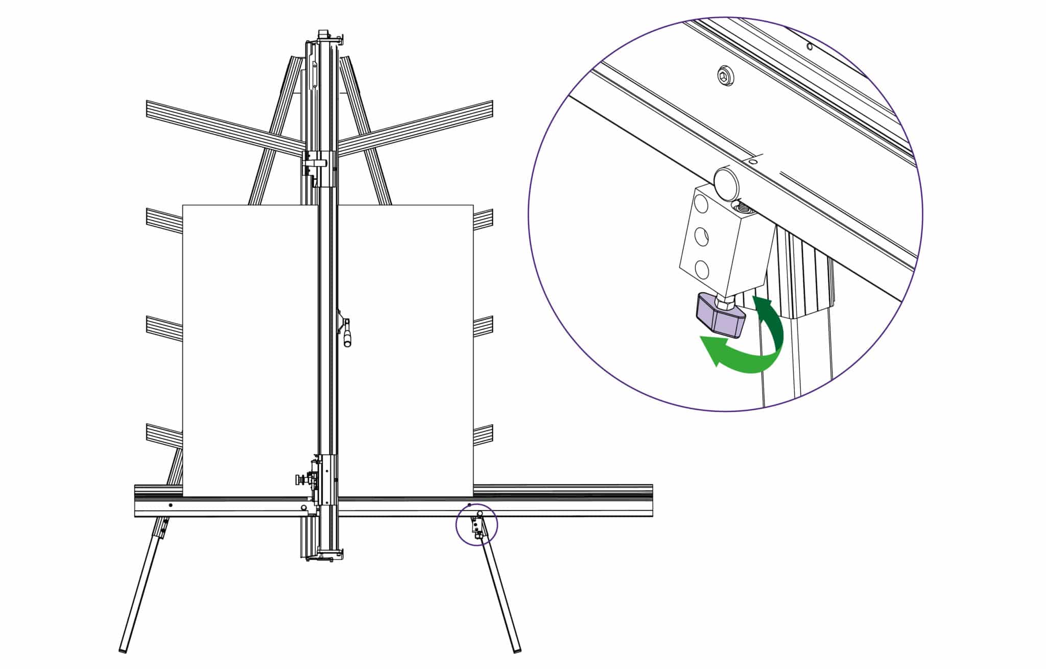
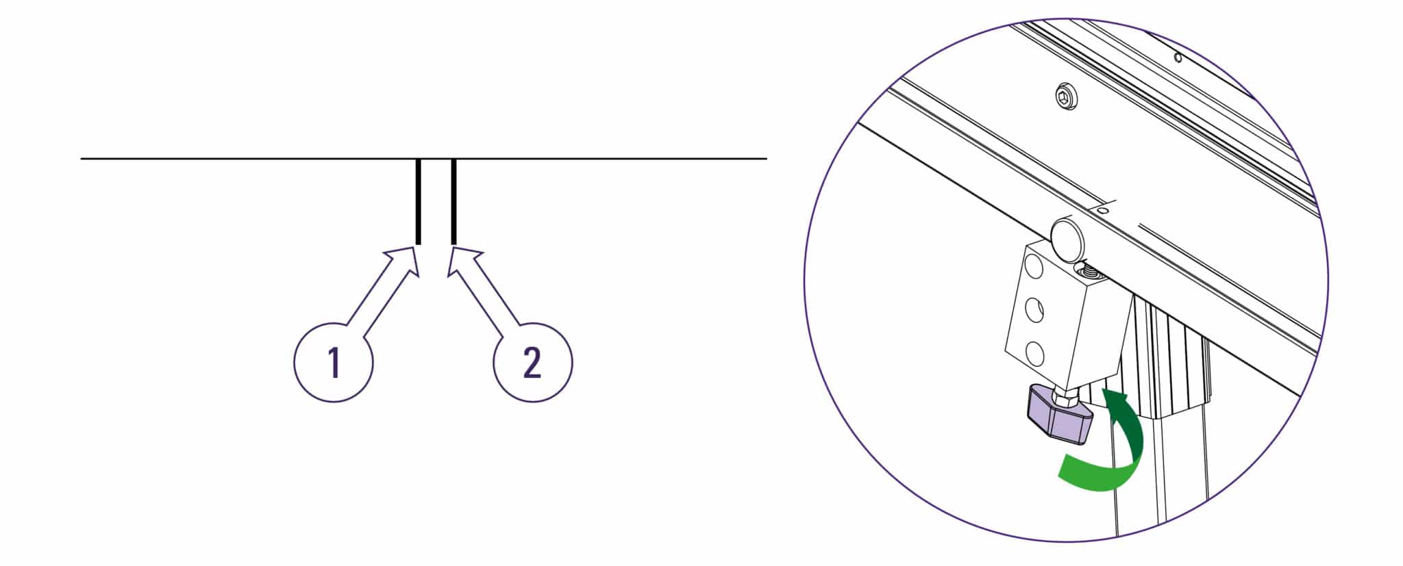
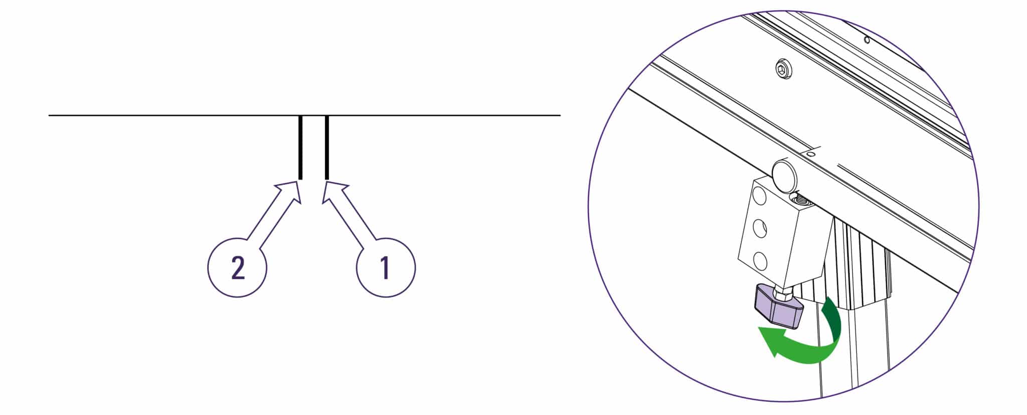
Turn the squaring adjustment knob on the right hand leg in the direction described next dependent upon the position of the top two cuts.
If the second cut is to the right of the first cut turn the adjustment screw clockwise when viewed from underneath.
If the second cut is to the left of the first cut turn the adjustment screw counter-clockwise when viewed from underneath.
The adjustment screw should be moved so that when the blade is moved to the top of the board it cuts between two existing cuts, the plastic sightline fixed to the edge of the clamp gives an indication where the machine is going to cut. Make sure that when assessing the location of the cut that the clamp has good contact with the material being used.
Repeat the squareness check. Tighten the screws using a 5mm Allen (hex) key and a 17mm spanner to tighten nut A once the squareness has been adjusted.
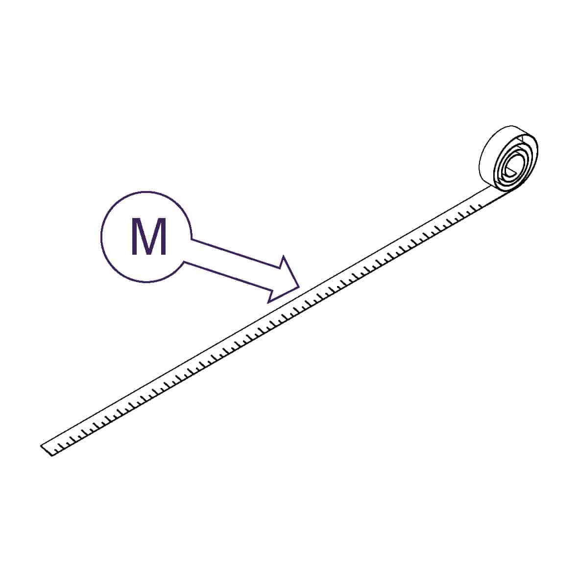
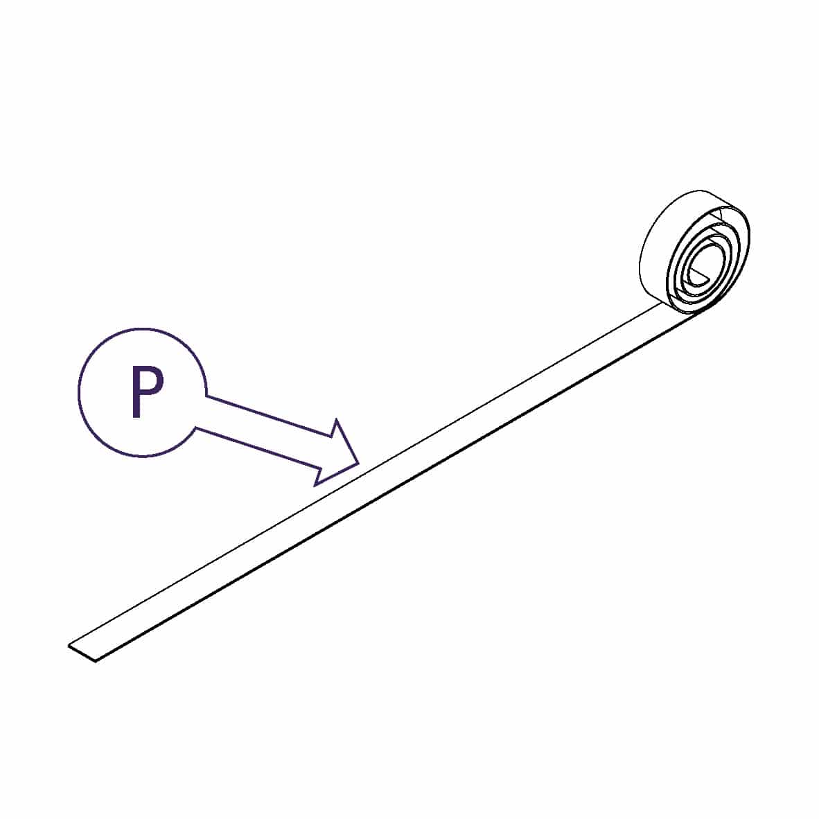
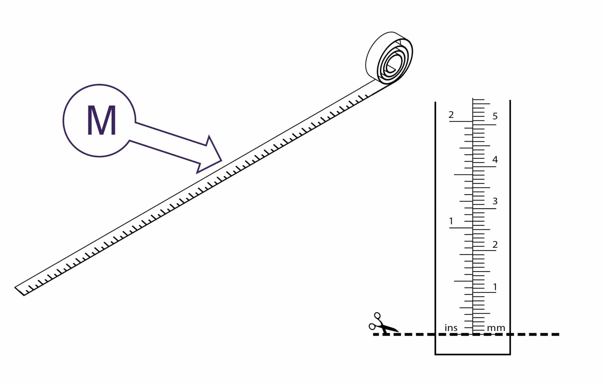
Trim the bottom of the scale at zero with scissors
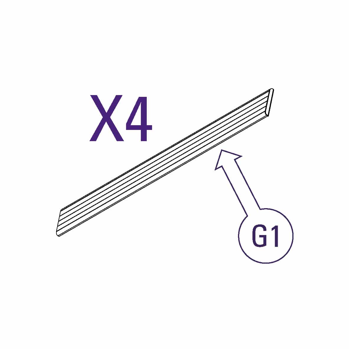
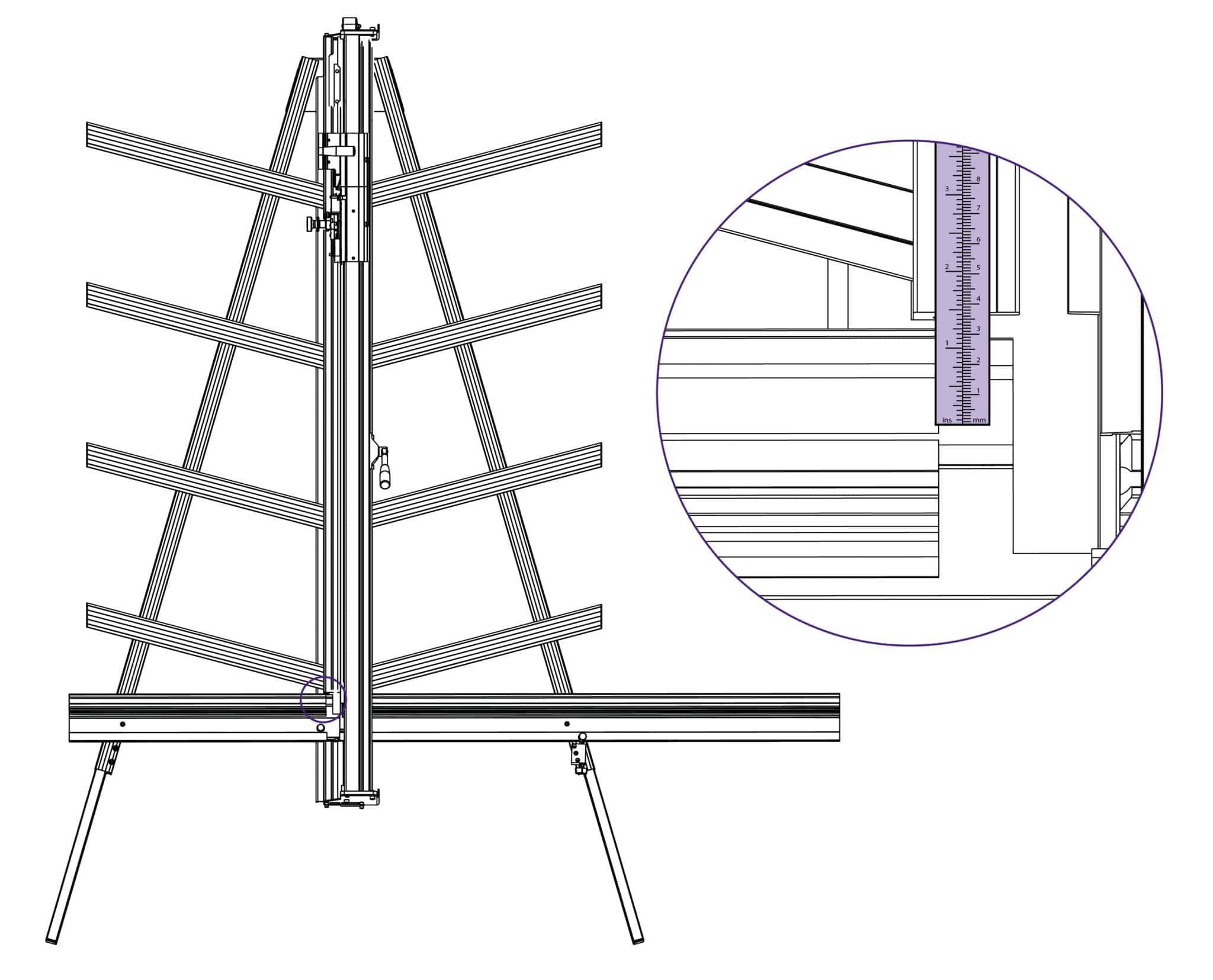
Remove the paper backing tape and carefully place the rule adjacent to its groove in the main body and with the zero end resting inside the material channel of the squaring arm. When aligned stick the rule in its groove.
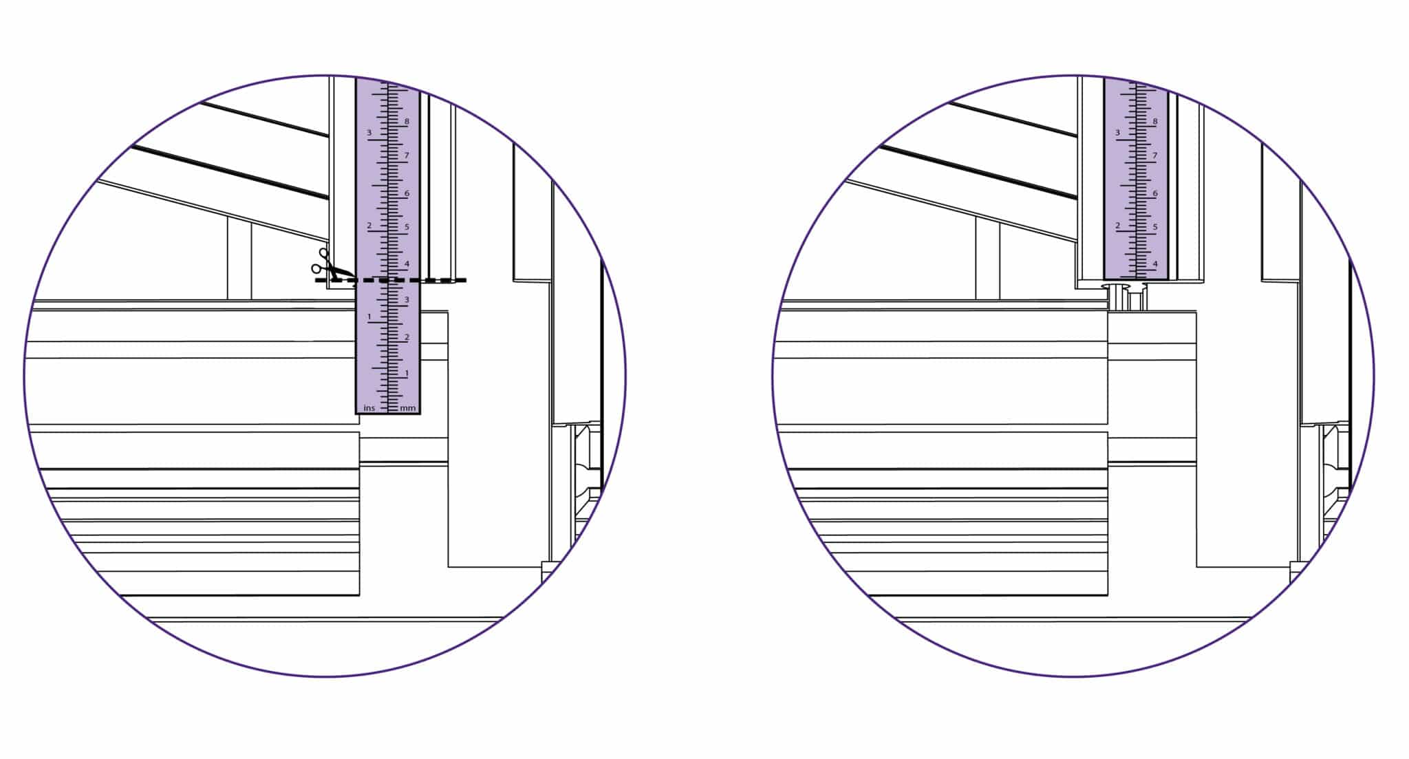
Again trim the rule at the bottom end as shown.
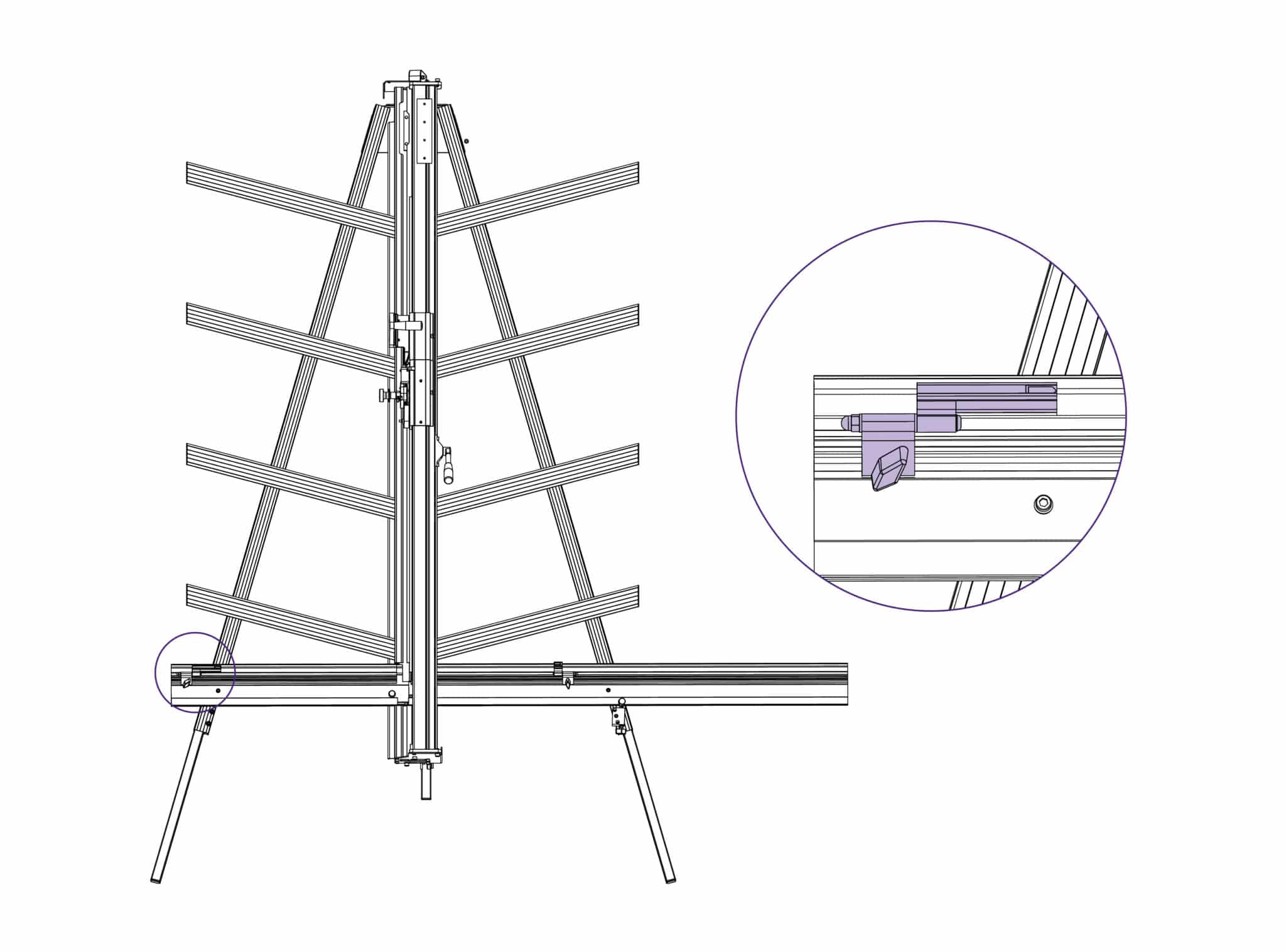
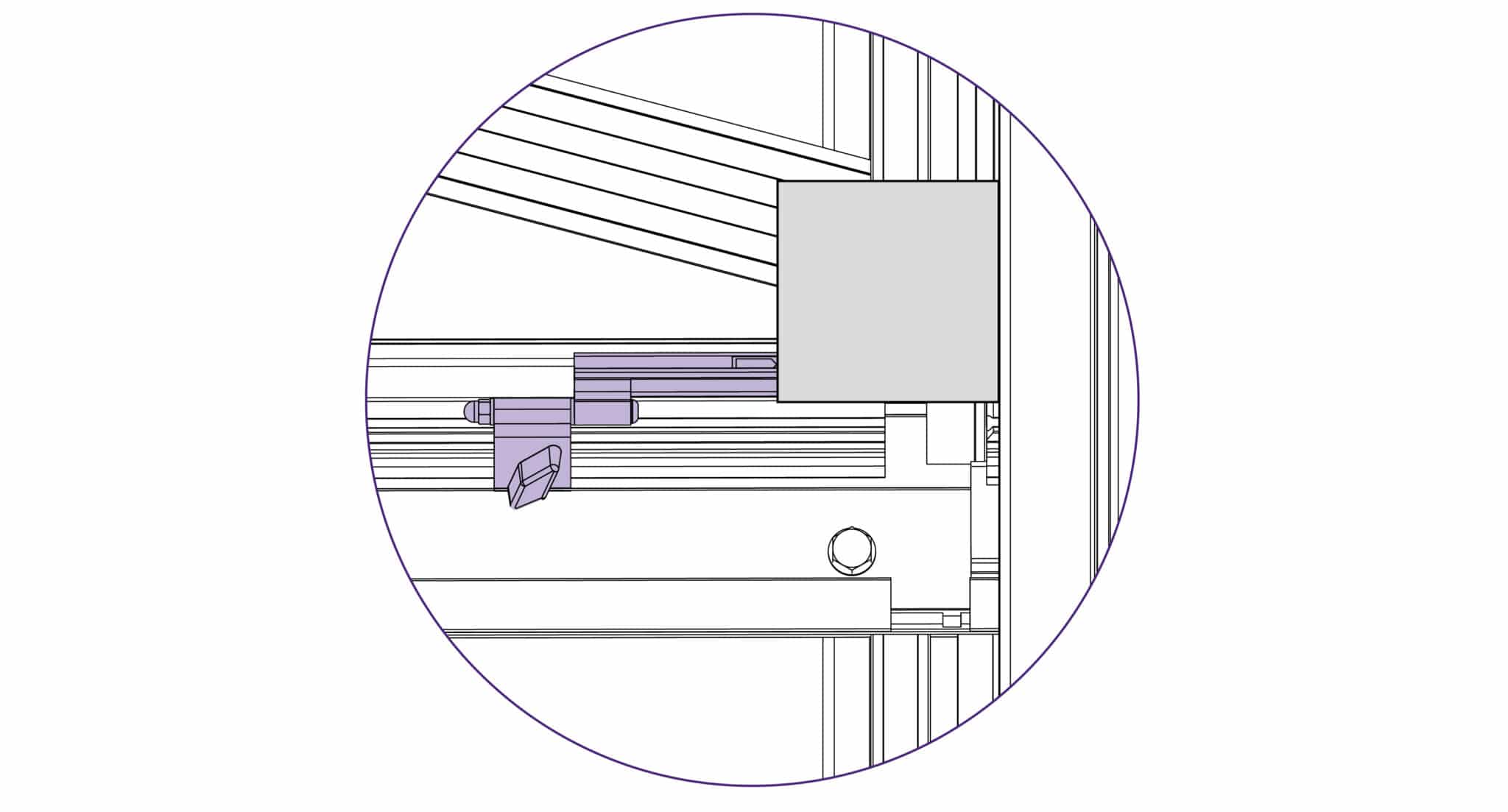
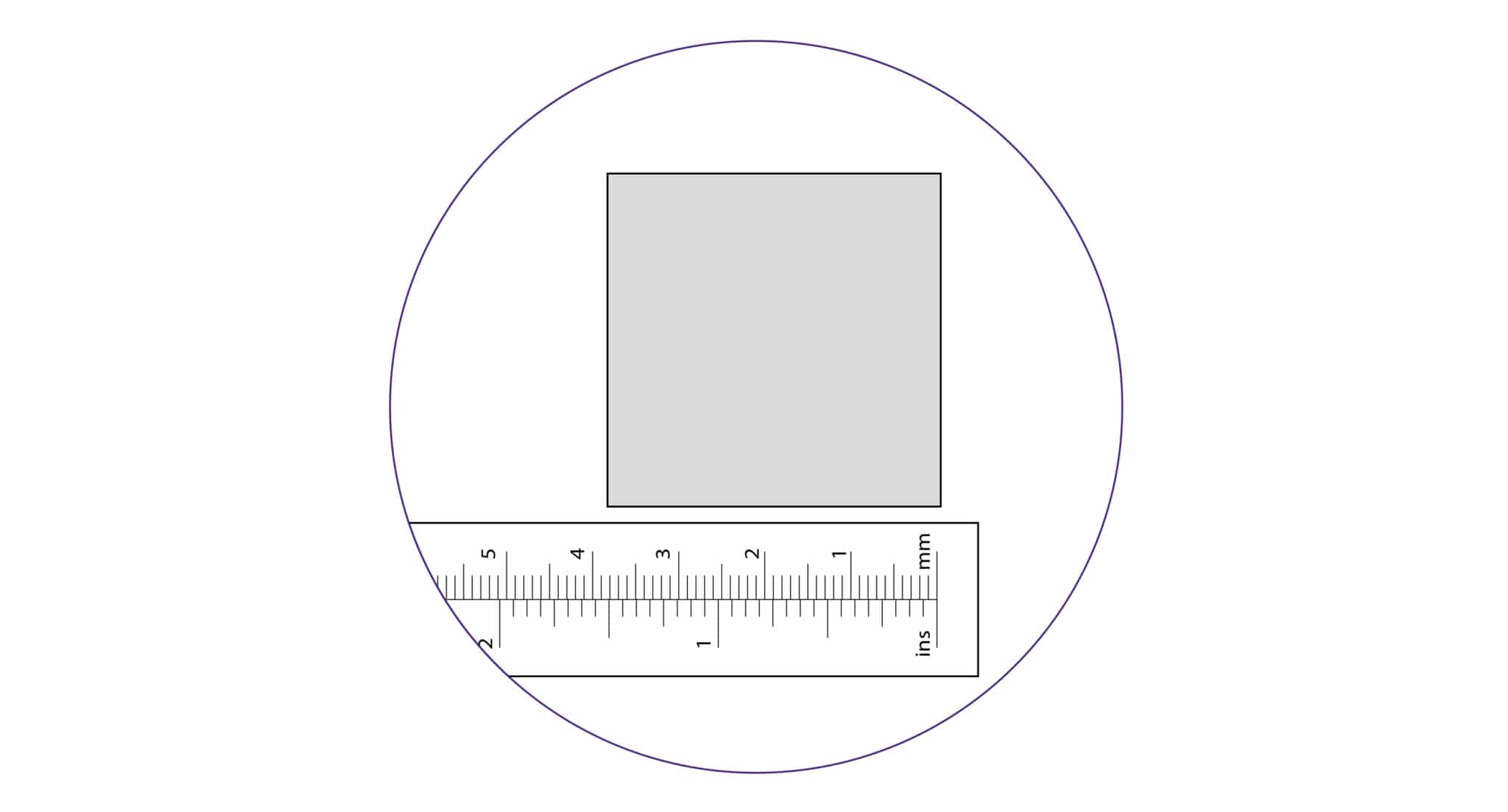
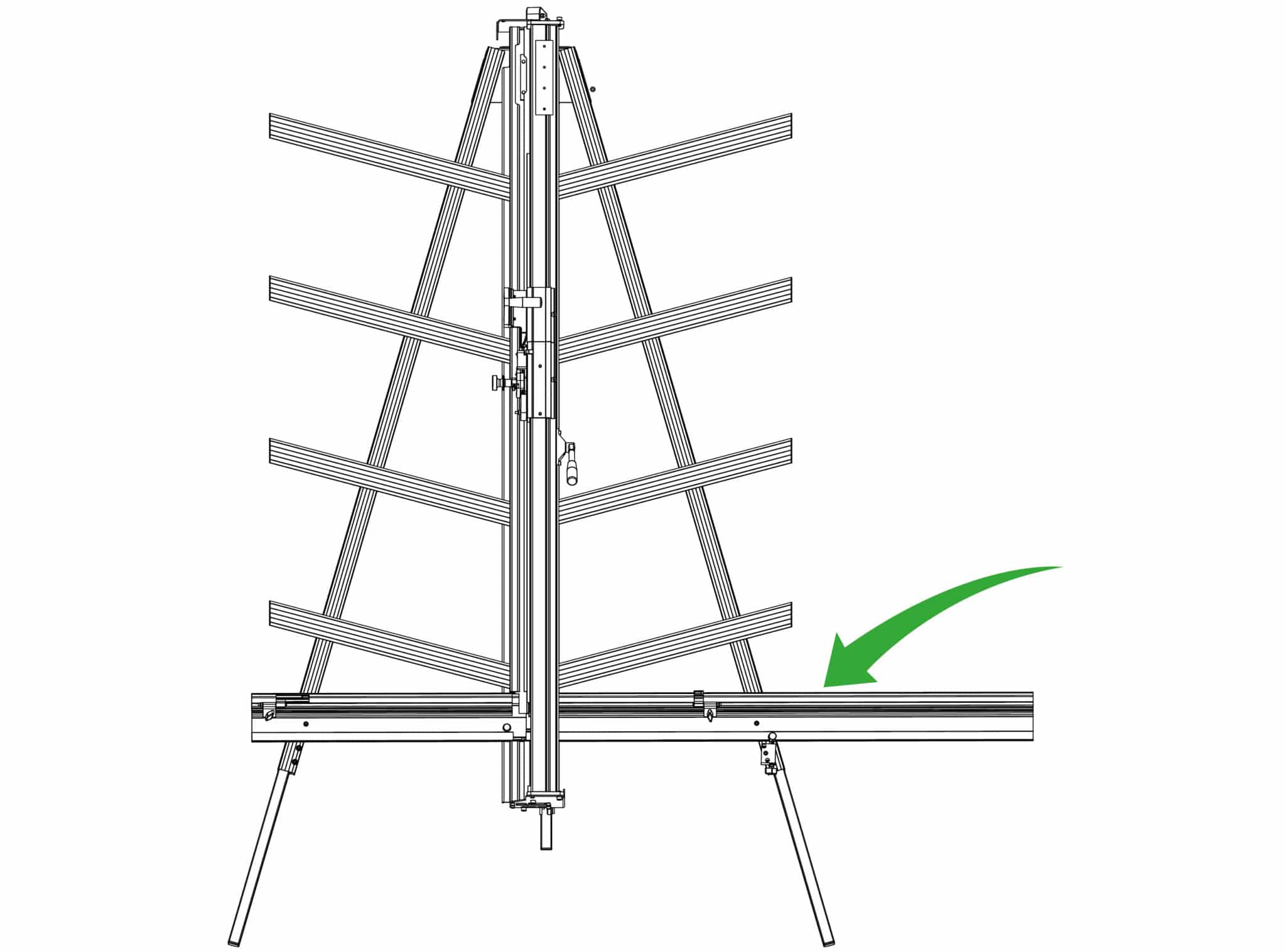
The top edge of the squaring arm slides left to right to enable calibration. Use the 3mm Allen (hex) key to loosen the screw in the back of the squaring arm if adjustment is necessary.
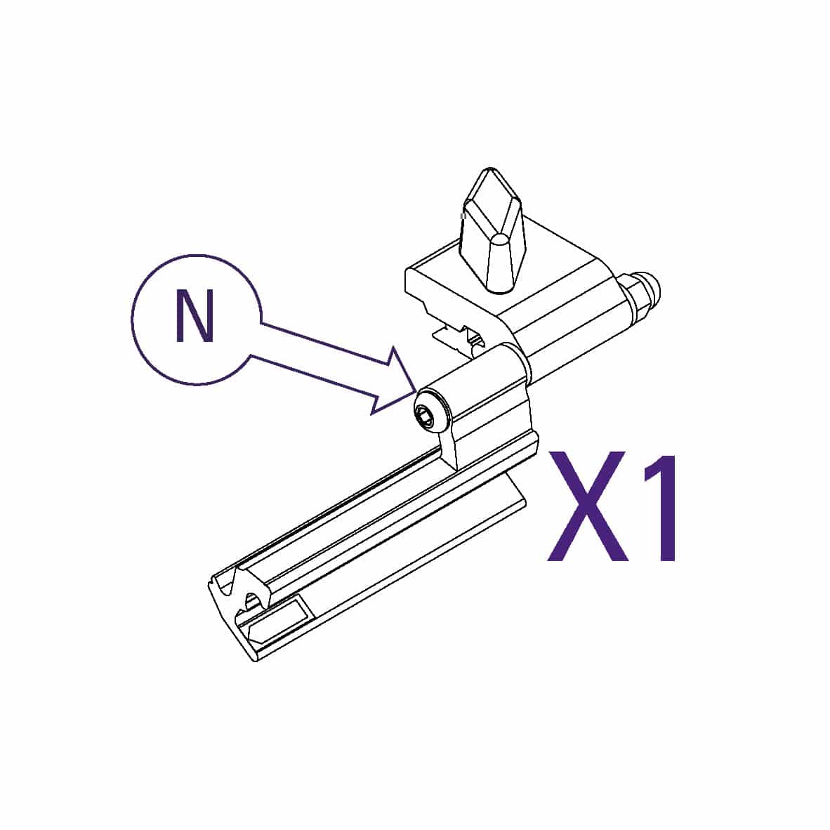
Slide the production stop onto the outside edge of the squaring arm as shown.
Clamp a piece of card in the machine and move the production stop to it.
Cut the card and measure, adjust the sliding scale so that the production stop indicates the measured size.
Repeat the process for the other side of the machine.
Registering your Excalibur 3S machine will activate your 5 year guarantee.
See the Excalibur 3S User Guide for advice on cutting techniques, using the different cutting heads and care and maintenance of your machine.

