
How to replace the PVC panels on the Excalibur 6000
To do this you will need the Excalibur 6000 Replacement PVC panel kit >
Tools required:
- Clean cloth
- White spirit
- Rigid item (i.e. Ruler)
NOTE: Do not bend the panels when fitting
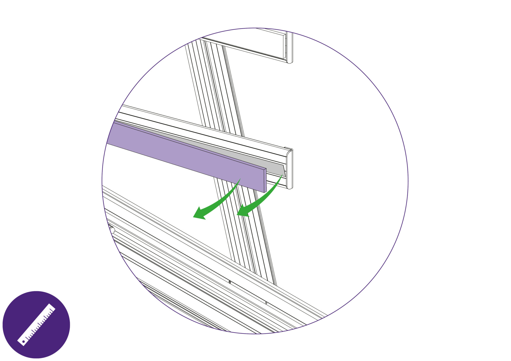
Removing from the support arm:
- Slightly remove the edge of the blue support board using a thin and rigid item such as a ruler.
- Peel the layers of double sided tape from the support arm if any tape remains on the surfaces.
- Clean the surface of the support arm with white spirit to clear any remnants of adhesive.
- Ensure the surface is clean and dry before fitting the new blue support oards onto the support arms.

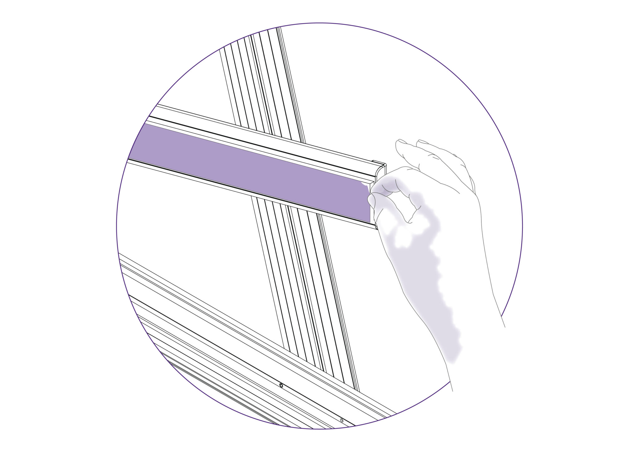
Placing onto the support arms:
- Peel the release paper from the adhesive face and align the angled face of the board with the angled face of the aupport arm that does not have the end cap attached.
- Ensure that the board in central to the support arm and that it does not overlap on to the main body face.
- Proceed to lower the blue support board onto the support arm surface, starting from the aligned edge.
- Remove the protective film.
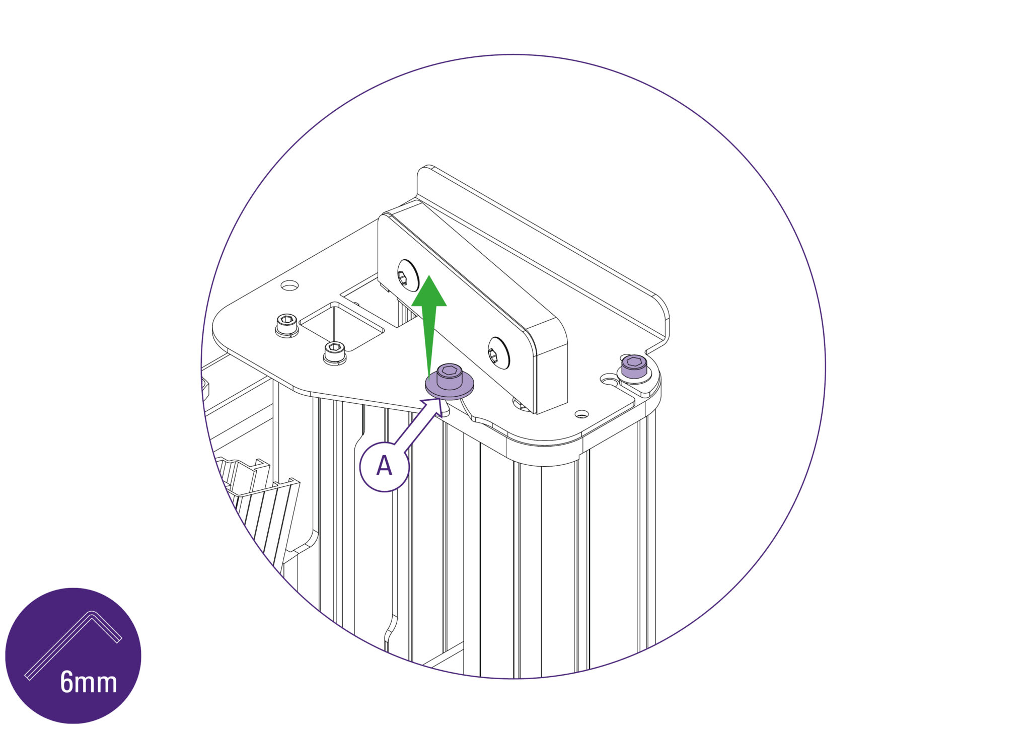
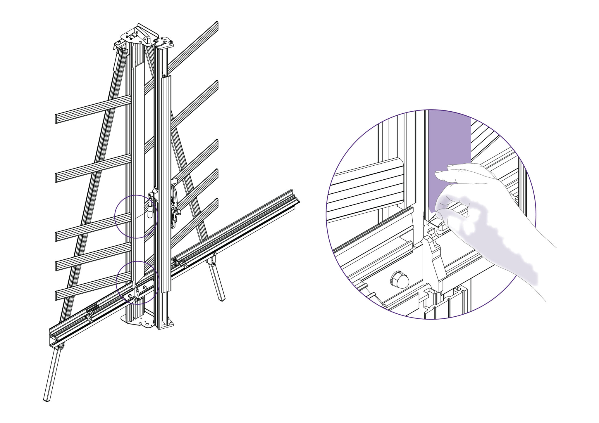
Removing from the main body:
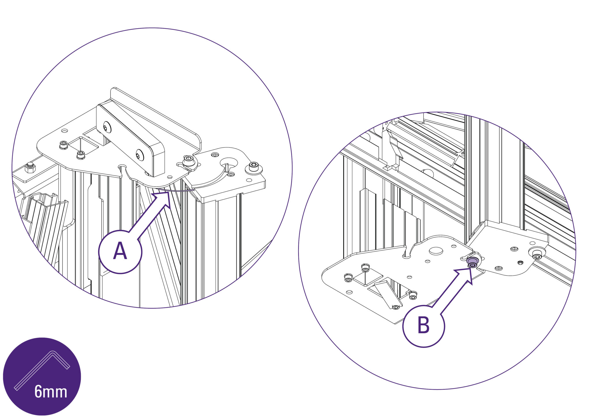
- Loosen the two screws using the 6mm Allen key (hex key) on the mount plate of the machine, as indicated.
- The left hand one needs to be undone enough for the flanged washer (A) to be lifted clear of the top plate, or it can be entirely removed if you prefer but do not remove the other screw.
- Repeat this at the bottom end of the machine.
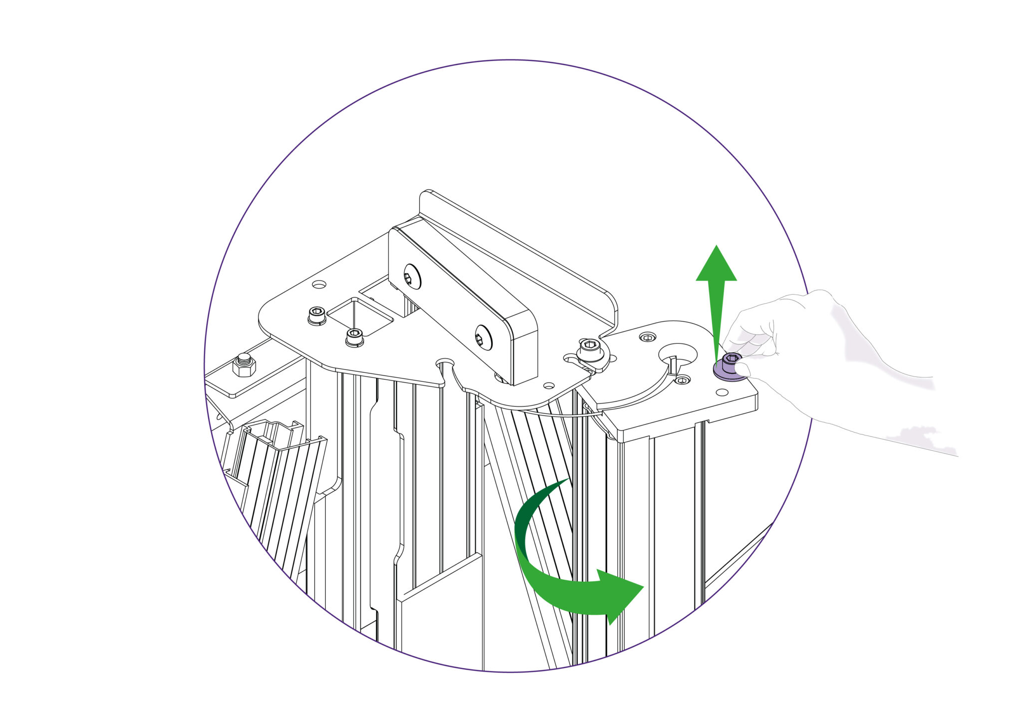
- Ensure the clamp is fully open.
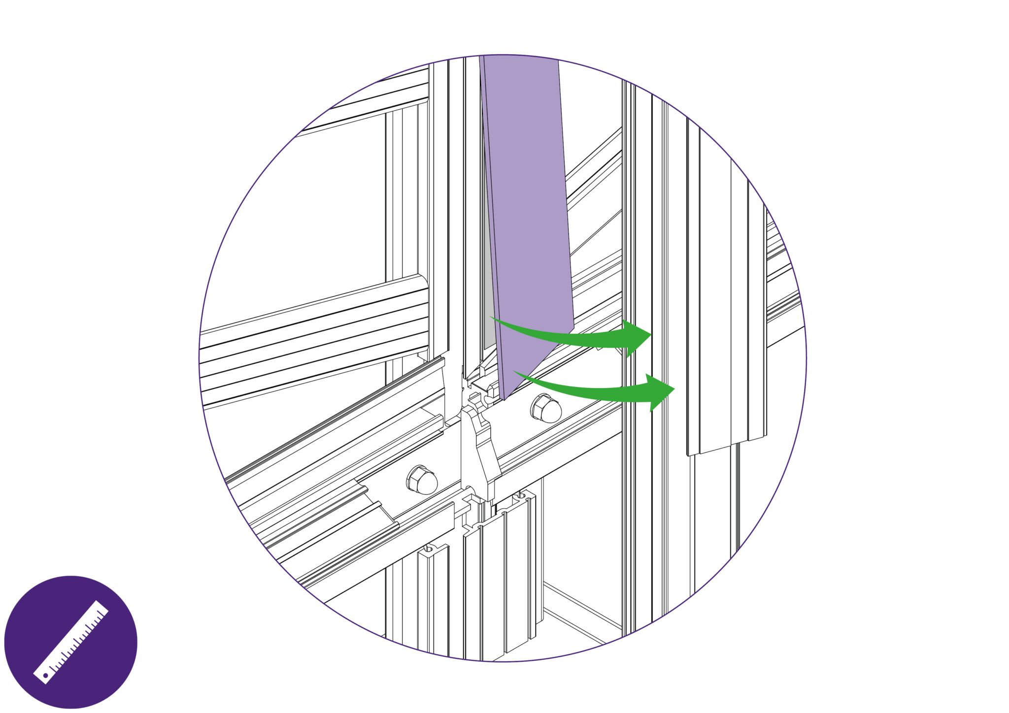
- Then whilst lifting the flanged washer clear with one hand, take hold of the slideway and twist it out as shown.
- Once the flanged washer is clear of the top plate it can be released.
- It is normal to feel the balance weight cord working against you.
- You will feel the balance weight cord (A) working against you and try to twist the slideway back, open the slideway carefully and watch that the balance weight cord (A) does not become trapped.
- Tighten the bottom Allen screw (B), as shown, to hold the slideway open in the maintenance position.
- With the blue support board now accessible, slightly remove the edge away using a thin and rigid item such as a ruler. Peel the layers of double sided tape from the main body if any tape remains on the surfaces.
- Clean the surface of the main body with white spirit to clear any remnants of adhesive.
- Follow through with the same steps for the other blue support board on the main body.
- Ensure any remnant of cleaning spirit is dried off before proceeding to place the new blue support boards onto the main body.
Placing onto the main body:
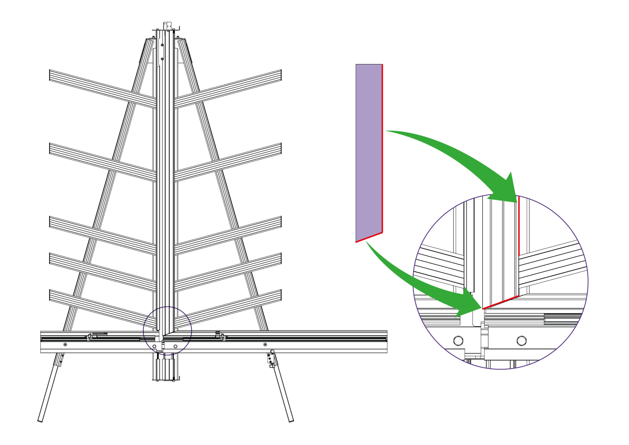
- Peel the release paper off the double sided tape and align the angled face of the lower board with the angled face of the main body.
- Ensure that the straight face identified is aligned with the face of the main body and that it does not overlap on to the support arms.
- Proceed to lower the lower blue support board onto the main body, starting from the aligned edges.
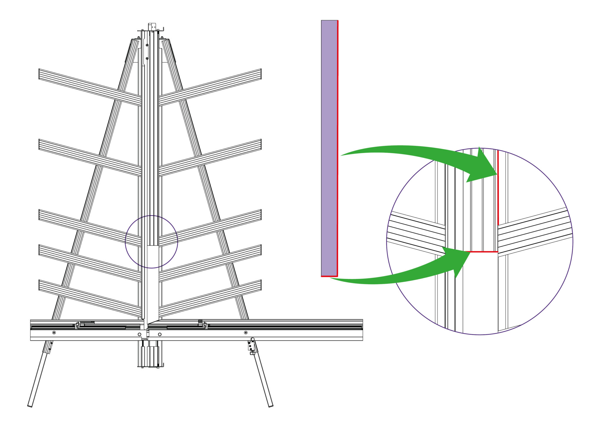
- Peel the release paper off the double sided tape and align the bottom face of the top board.
- Ensure that the flat face identified is also aligned with the face of the main body.
- Proceed to lower the top blue support board onto the main body, starting from the aligned edges.
- Remove the protective film.
- Proceed to return the slideway back into operating position and ensure that the cutting head runs up and down the full length of the slideway.
- Fasten the respective screws tightly.
Ⓒ Keencut 2020 | Baird Rd, Corby NN17 5ZA United Kingdom | Contact us
Created by DeType | Privacy | Website Disclaimer | Terms & Conditions