How to replace the multi tool cutting head on the Excalibur 6000
To do this you will need an Excalibur 6000 multi-tool cutting head >
Tools required:
- 6mm spanner/wrench
- 8mm spanner/wrench
- 13mm spanner/wrench
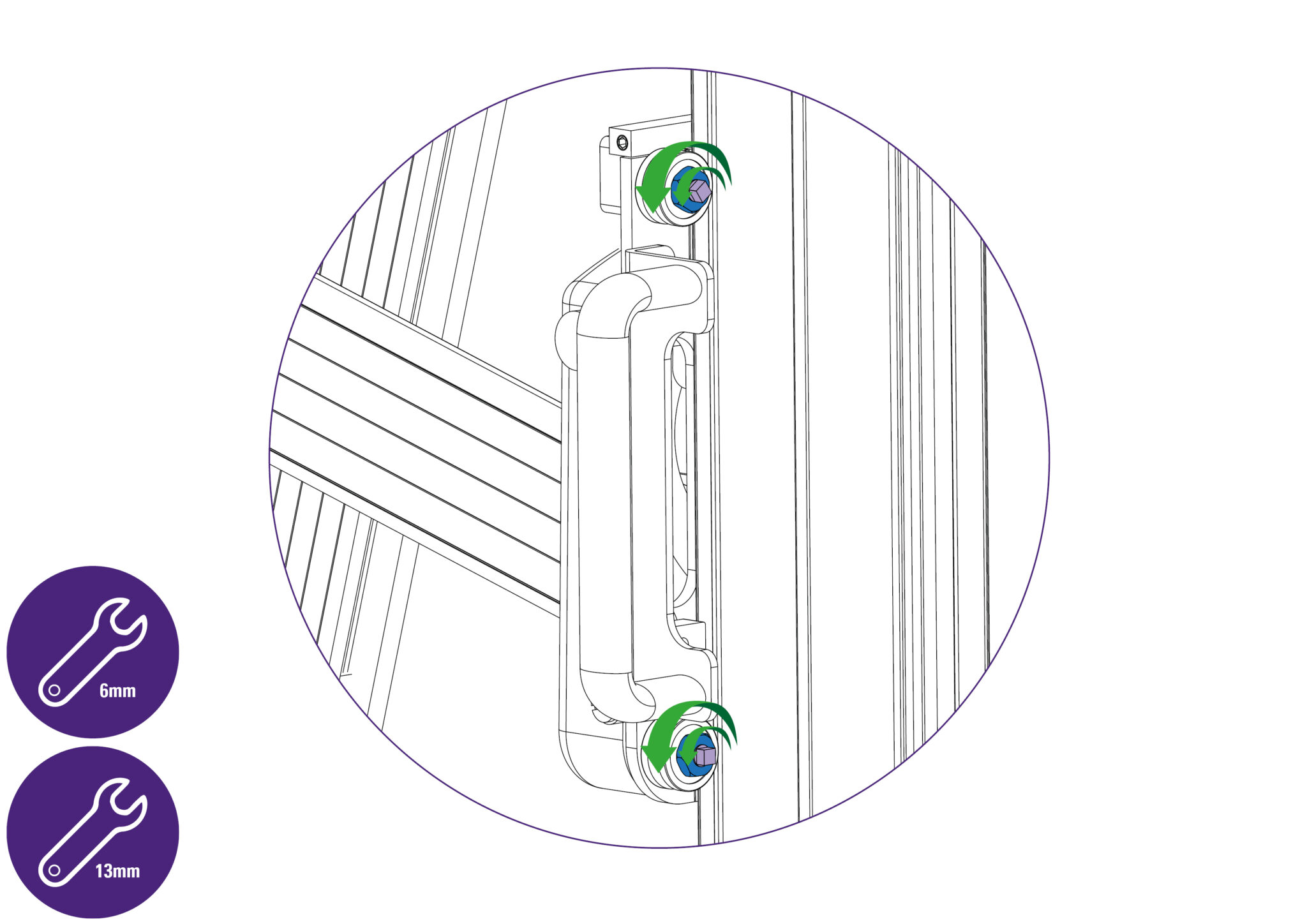
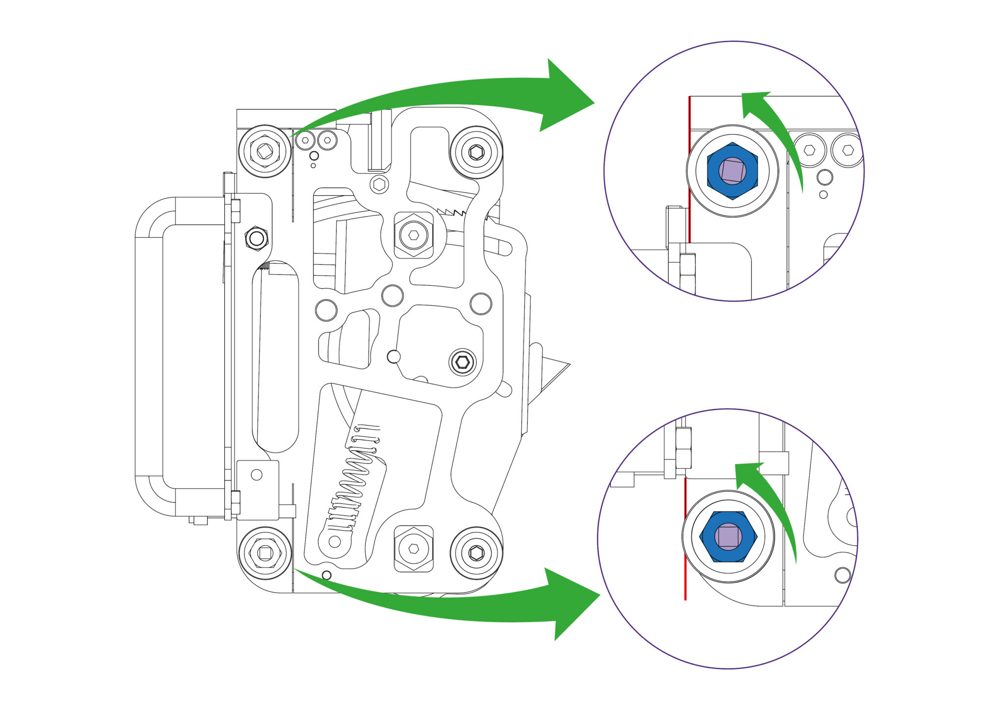
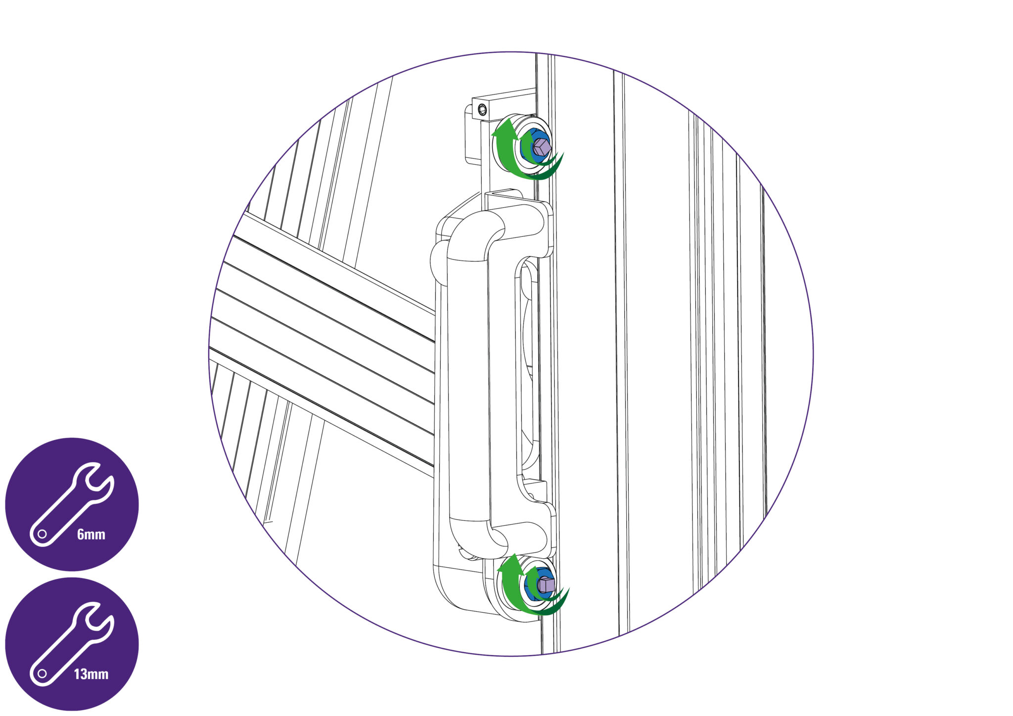
- Using a 13mm spanner/wrench, loosen the black nuts on each bearing (highlighted in blue) by one full turn.
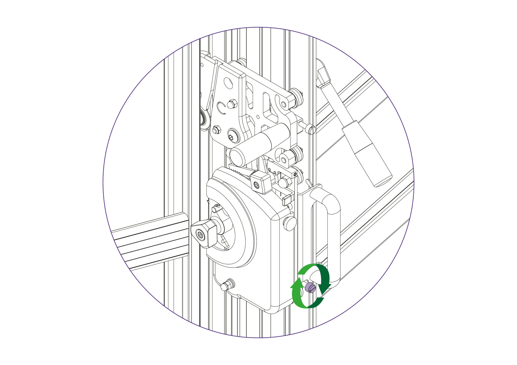
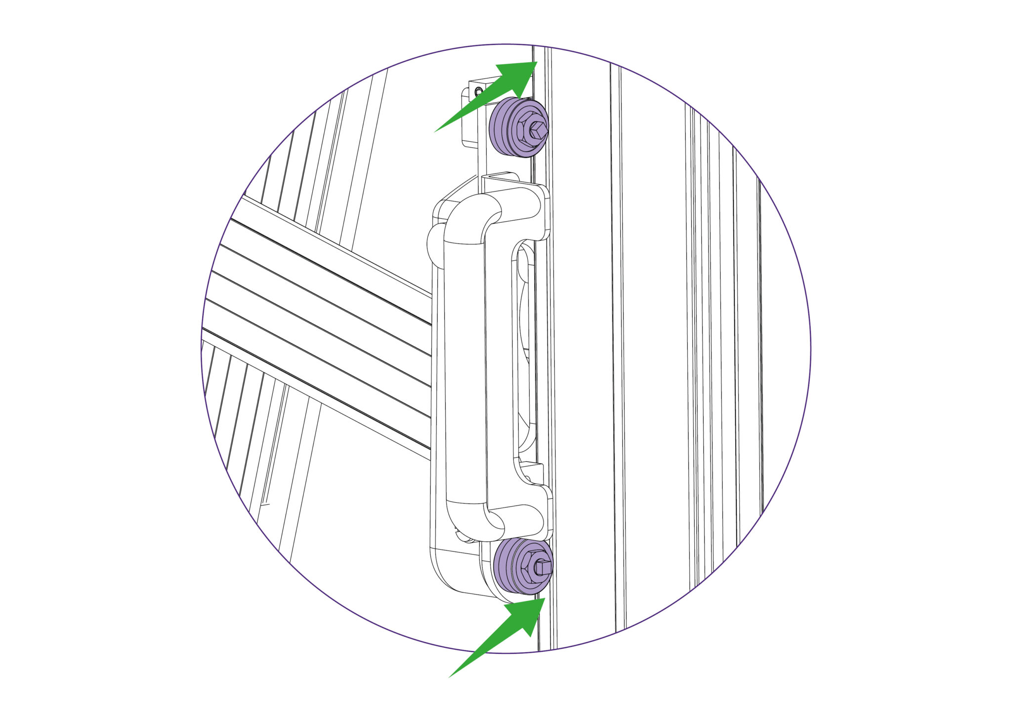
- Then loosen the black eccentric screws on each bearing (highlighted in purple) by half a full turn using a 6mm spanner/wrench, such that the bearings come away from the guide rods.
- It is important that the black eccentric screws are not loosened more than is necessary as otherwise the disc spring (located adjacent to the bearing) will be displaced on the screw’s shaft.
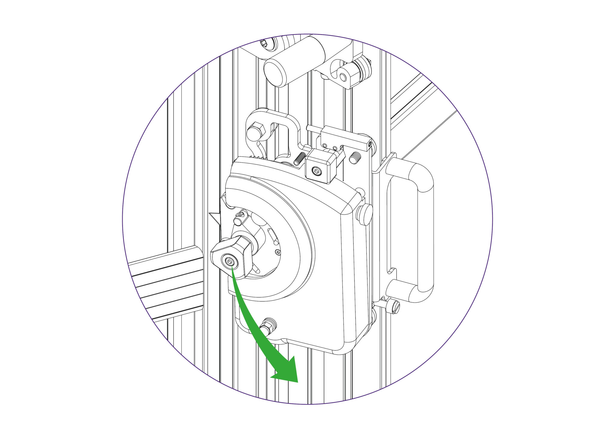
- Then whilst pushing the cutter head towards the back of the machine (with the loosened bearings engaging with the guide rods) rotate the cutter head outwards to bring the fastened bearings (at the far end of the head away from the handle) out of engagement with the guide rods, and off the machine.
- On the replacement cutter head, use a 13mm spanner/wrench, to loosen the black nuts on each bearing (highlighted in blue) by one full turn. Loosen it more in half turn increments if necessary based on the following step.
- Loosen the black eccentric screws on each bearing (highlighted in purple) using a 6mm spanner/wrench, such that the bearings are shifted furthest away from the center of rotation of the bearings (past the edge of the cutter head highlighted in red).
- It is important that the black eccentric screws are not loosened more than is necessary as otherwise the disc spring (located adjacent to the bearing) will be displaced on the screw’s shaft.
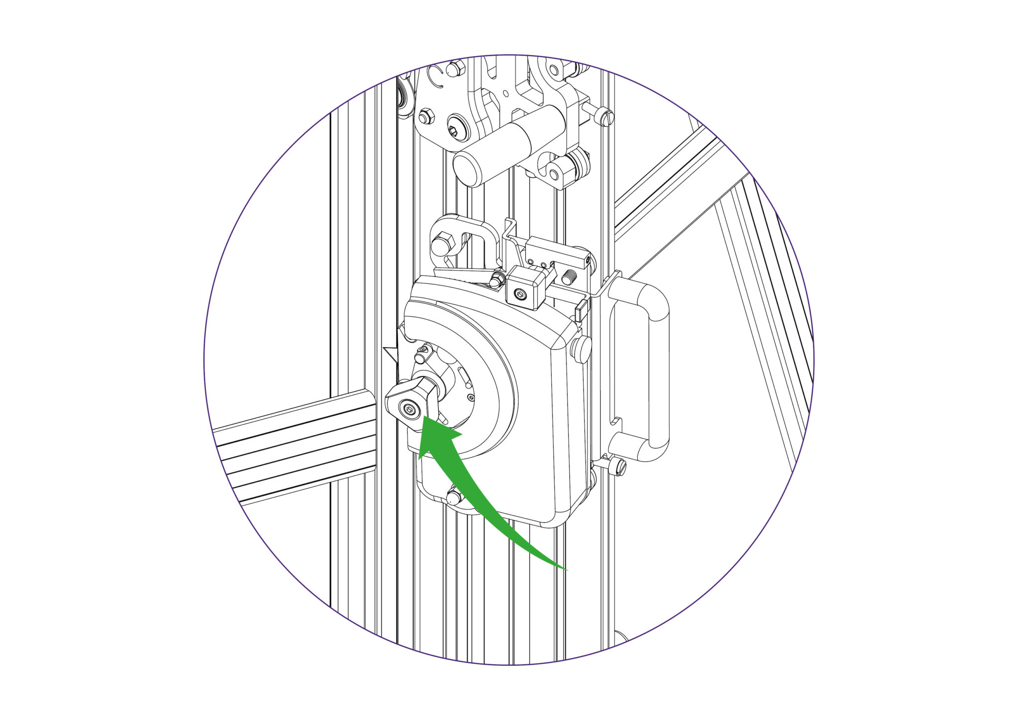
- Align and engage the loosened bearings with the guide rods towards the front of the machine, and rotate the cutter head inwards (as was done earlier but in reverse).
- Then whilst pulling the cutter head towards the front of the machine (with the fastened bearings engaging with the guide rods), tighten the black eccentric screws on each of the front two bearings using a 6mm spanner/wrench, until there is no wobble experienced on the cutter head.
- Follow up by tightening the black nuts on the front two bearings with a 13mm spanner/wrench, whilst holding the eccentric screws still using a 6mm spanner/wrench.
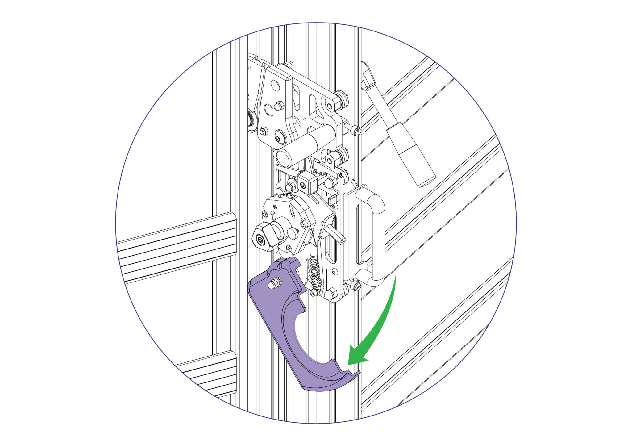
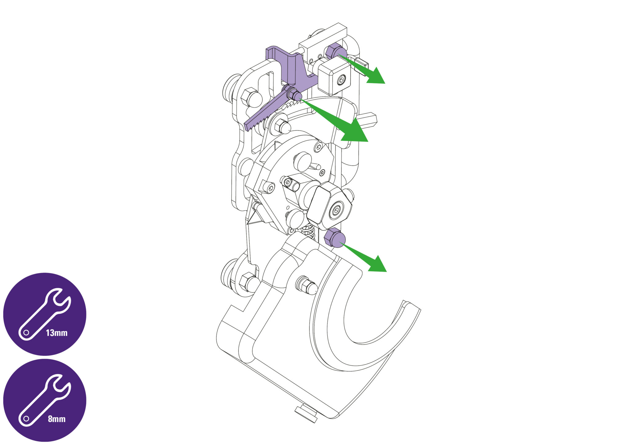
- Swing out the guard on the cutter head and tighten the M8 dome nuts. Then close the guard on the cutter head.

