
Excalibur 6000 installation manual – Squaring and Calibration
Note: It would be useful to cover the “Get to know your cutter”> sections in the User Manual before proceeding with the following steps.
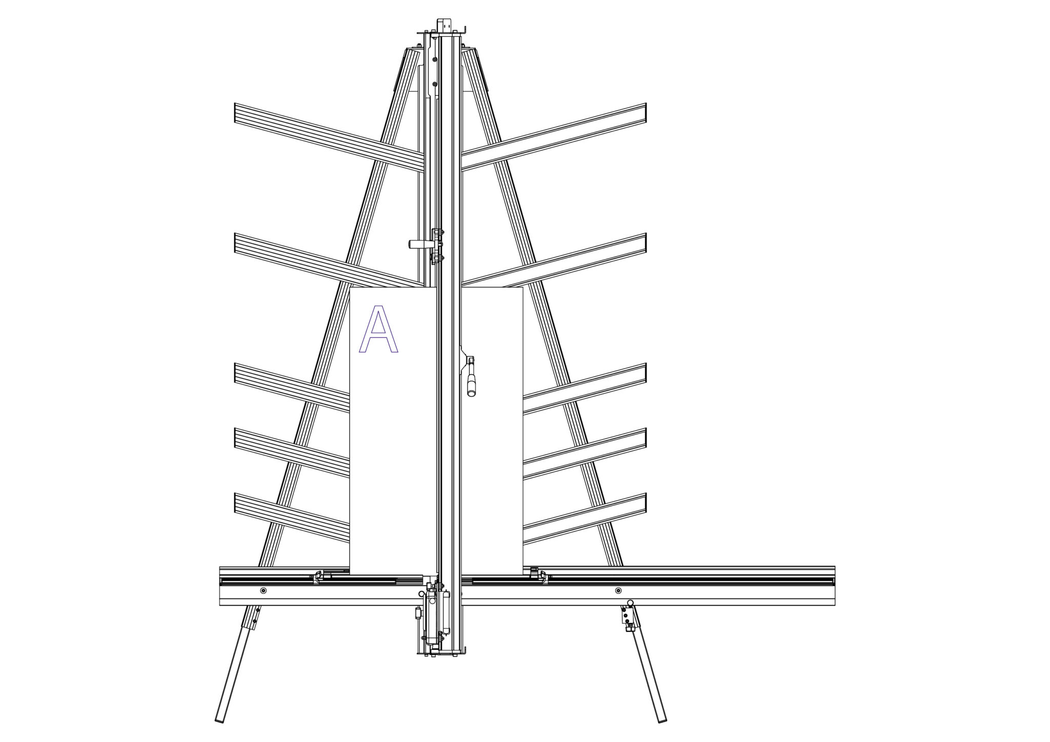
Place the board on the machine vertically as shown and apply the clamp ensuring the bottom edge is in firm contact with the Squaring Arm.
Select the cutting blade on the Multi-Tool Cutting Head.
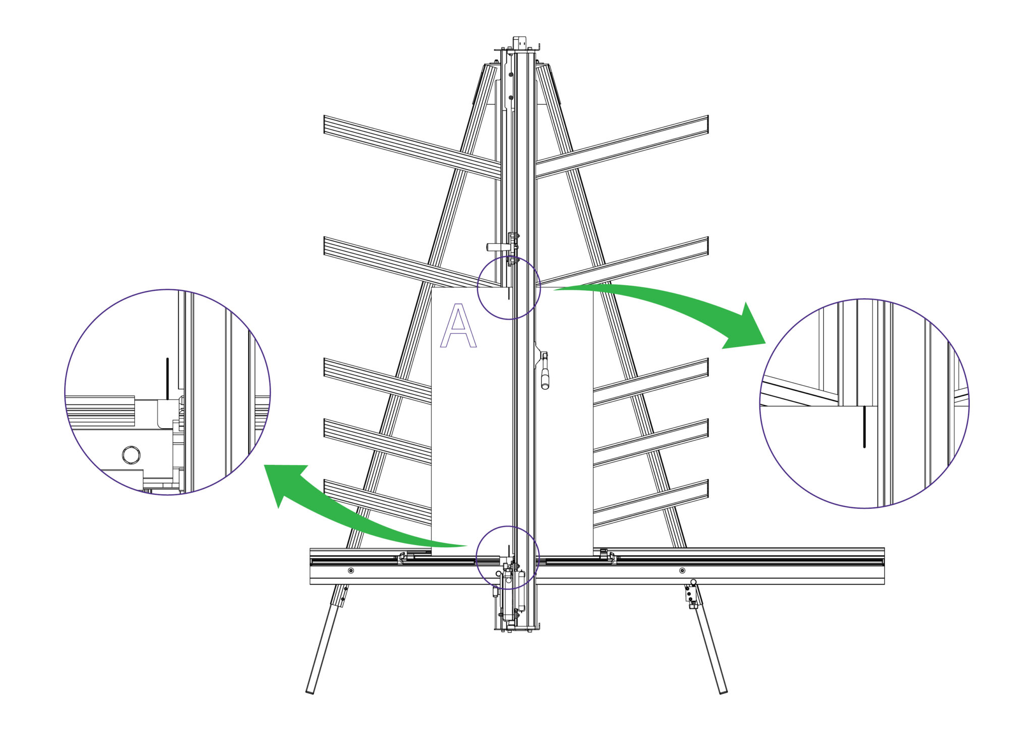
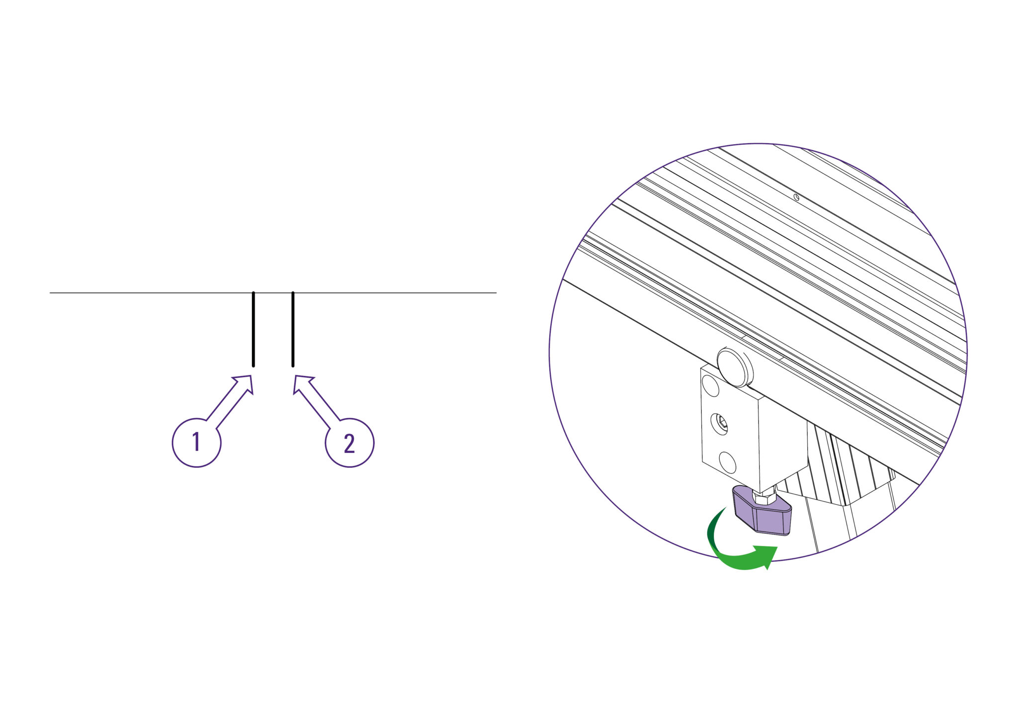
Cut into the top board to produce a cut approximately 3cm (1”) long. Disengage the cutter using the cutter release lever.
Lower the cutter and make a similar cut at the bottom of the board by pressing the blade through the board about 3cm (1″) from the bottom edge of the board.
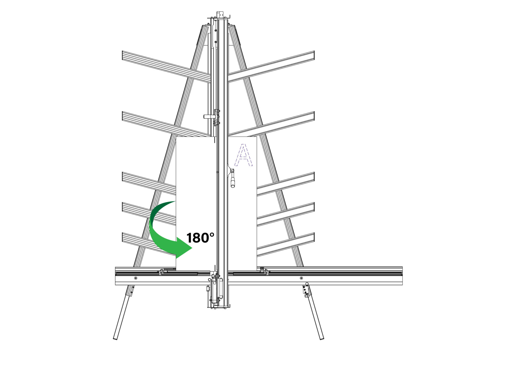
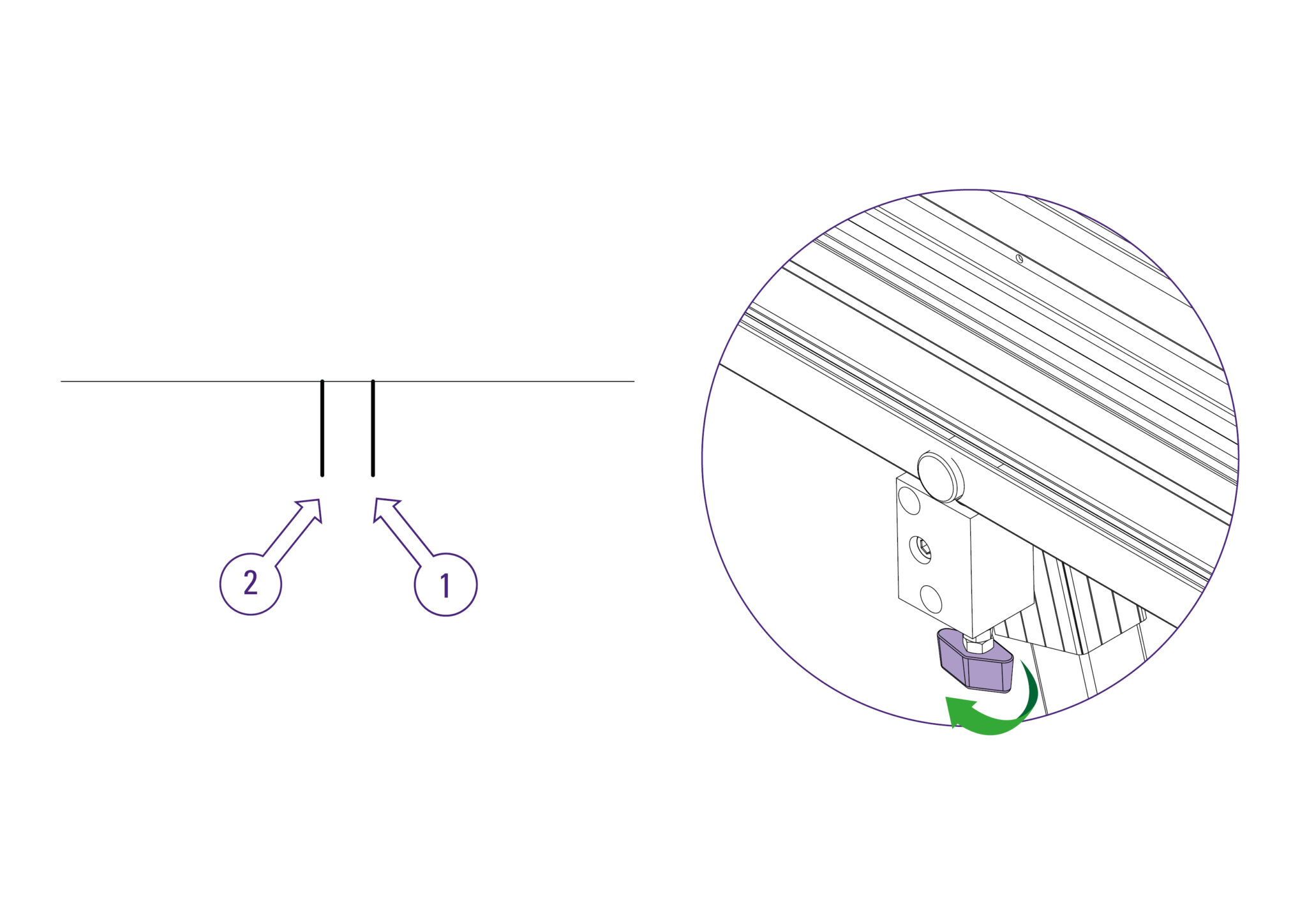
Unclamp and turn the board around laterally (like the page in a book) and place it back in the machine so the same edge is still on the Squaring Arm, but do not clamp it.
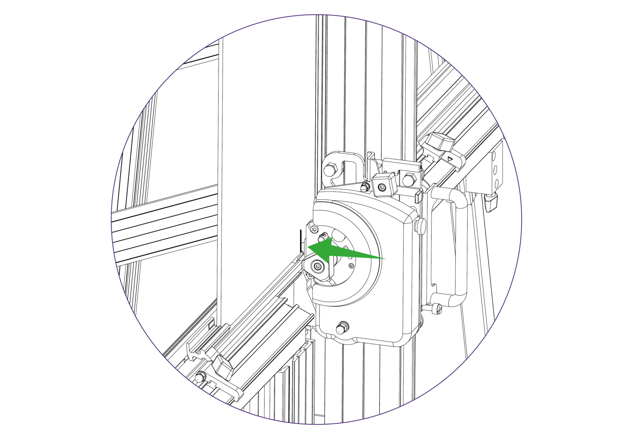
Align and engage the blade so it enters the previous made cut at the bottom edge of the board. Now apply the clamp.
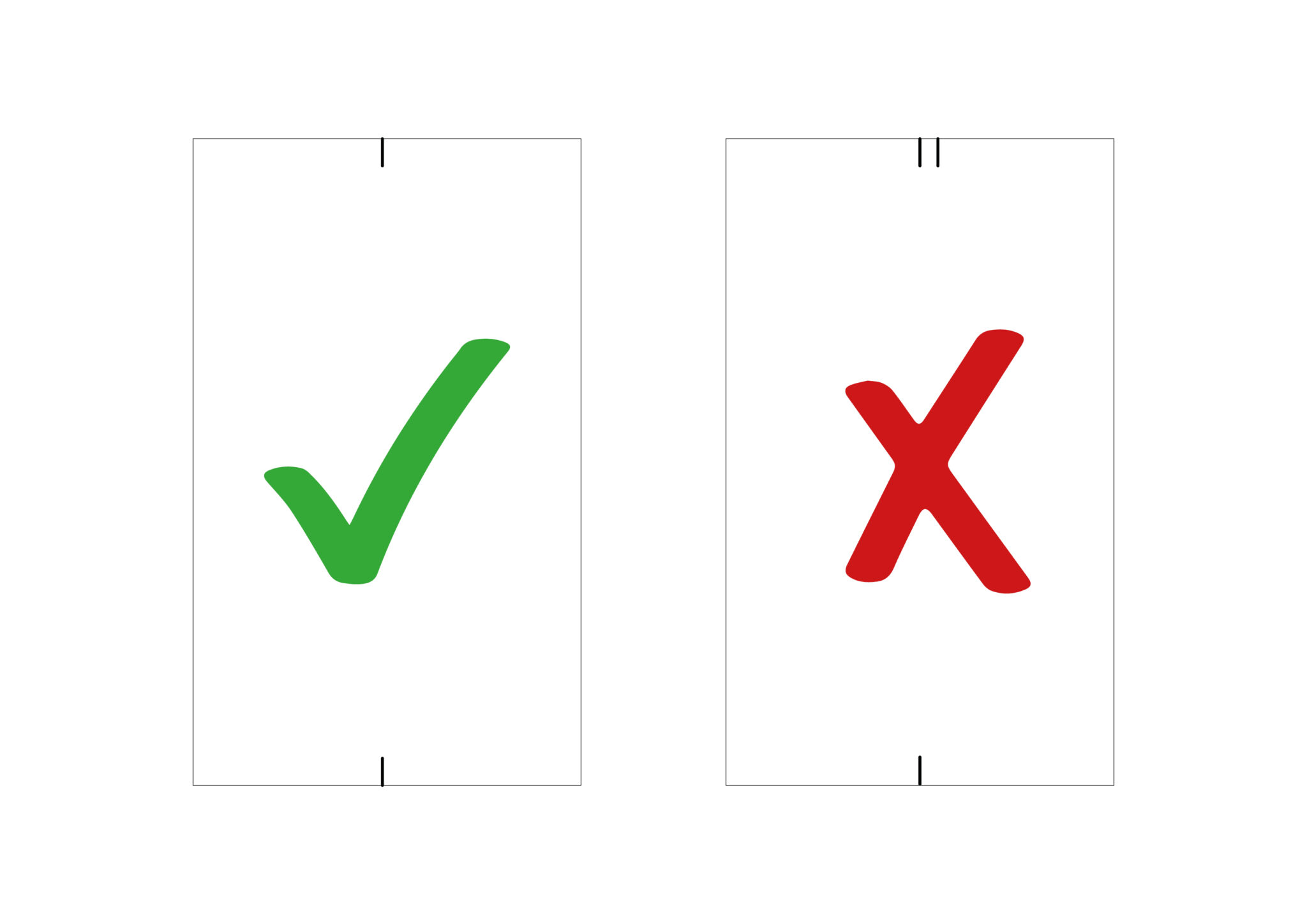
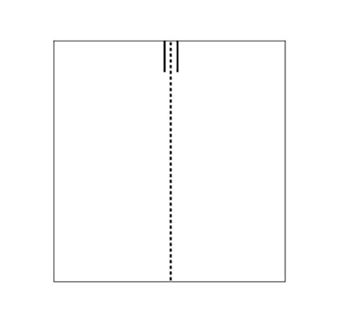
Raise the cutter to the top of the board, and if the machine is square the blade should enter the same cut as made previously. If not refer to Adjusting the squareness> to make the necessary
adjustment.
If it is square, continue to Calibrating the vertical scale>.
NOTE: Before making any adjustments carry out the squareness check as described in Checking the machine for squareness>
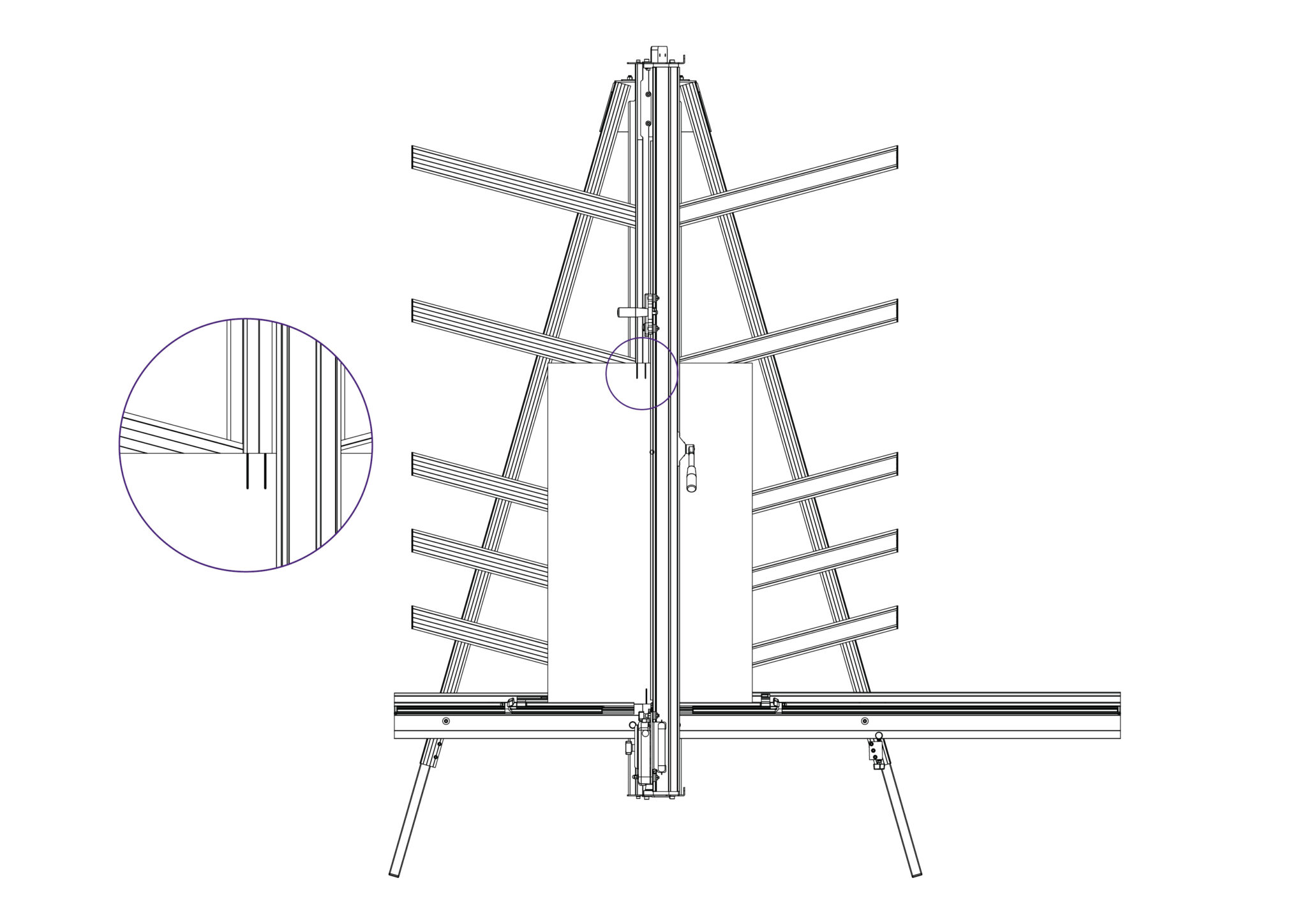
It is assumed that the board used for the test is still clamped in the machine. From the test results, determine if the last cut made in the top of the board is to the left or right of the previous cut.
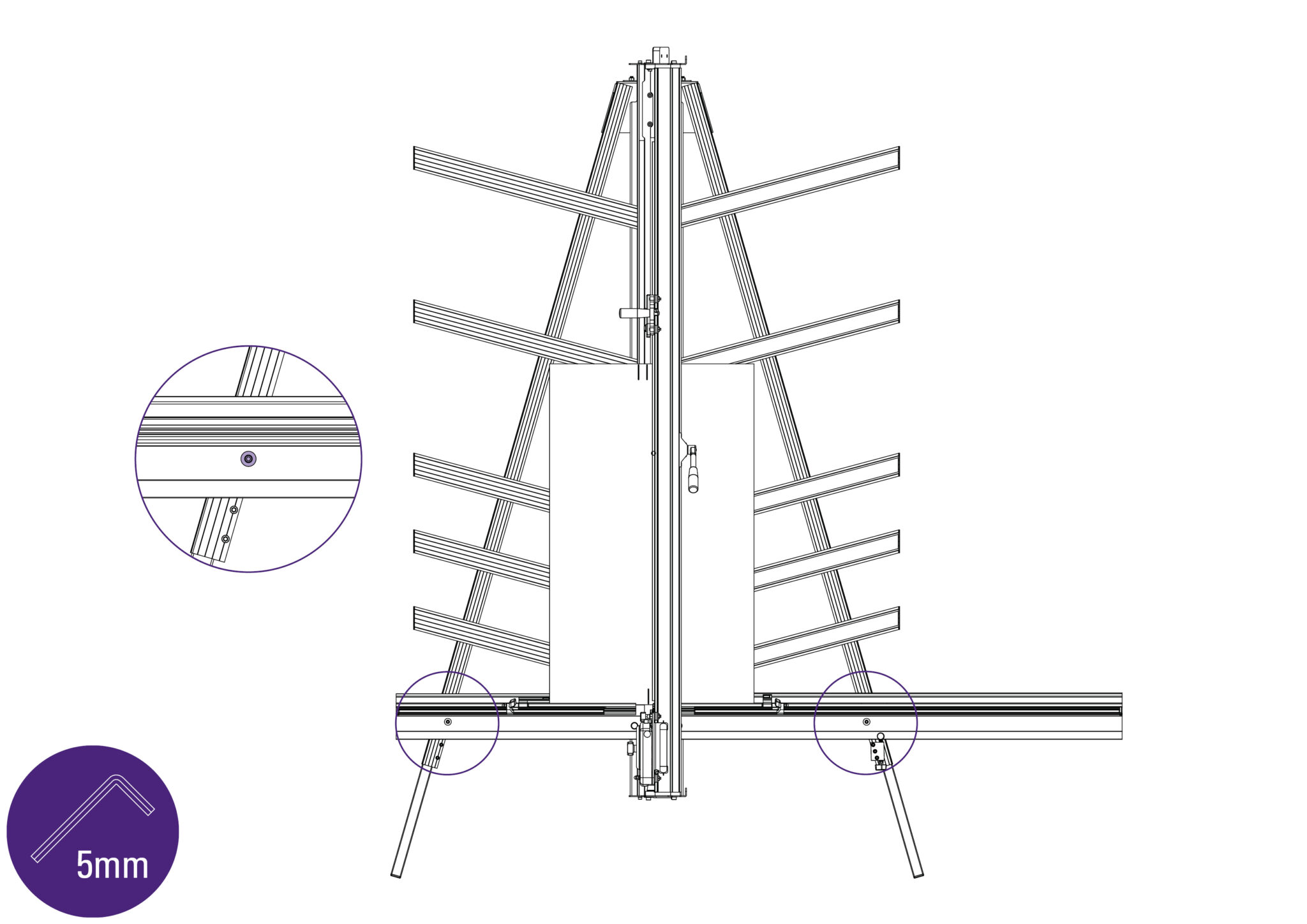
Use a 5mm Allen (Hex) key to slacken the two screws joining the squaring arm to the two legs.
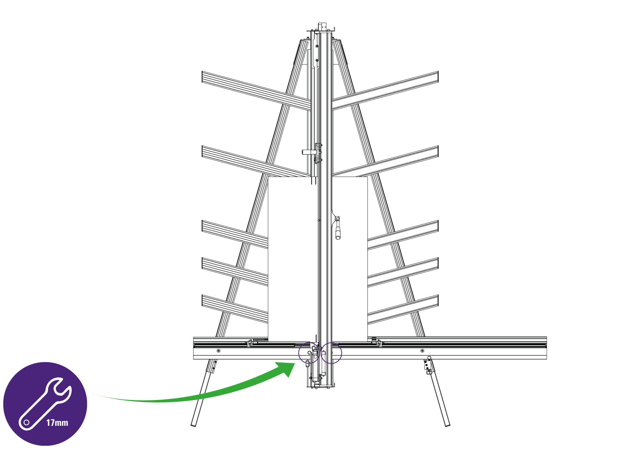
Use a 17mm spanner to slacken the left hand nut joining the Squaring Arm to the Main Body, and make sure the right hand nut is tight.
Release the clamp and position the board such that the blade is held in the cut on the bottom edge of the board. Press down on the board to make sure it is in good contact with the Squaring Arm.
Turn the squaring adjustment knob on the right hand leg in the direction described next, dependent upon the position of the top two cuts.
If the second cut is to the right of the first cut, turn the adjustment screw clockwise when viewed from underneath.
If the second cut is to the left of the first cut turn the adjustment screw counter-clockwise when viewed from underneath.
The adjustment screw should be incrementally turned so that when the blade is moved to the top of the board it cuts between two existing cuts. Make sure that when assessing the location of the cut the Squaring Arm has good contact with the material being used.
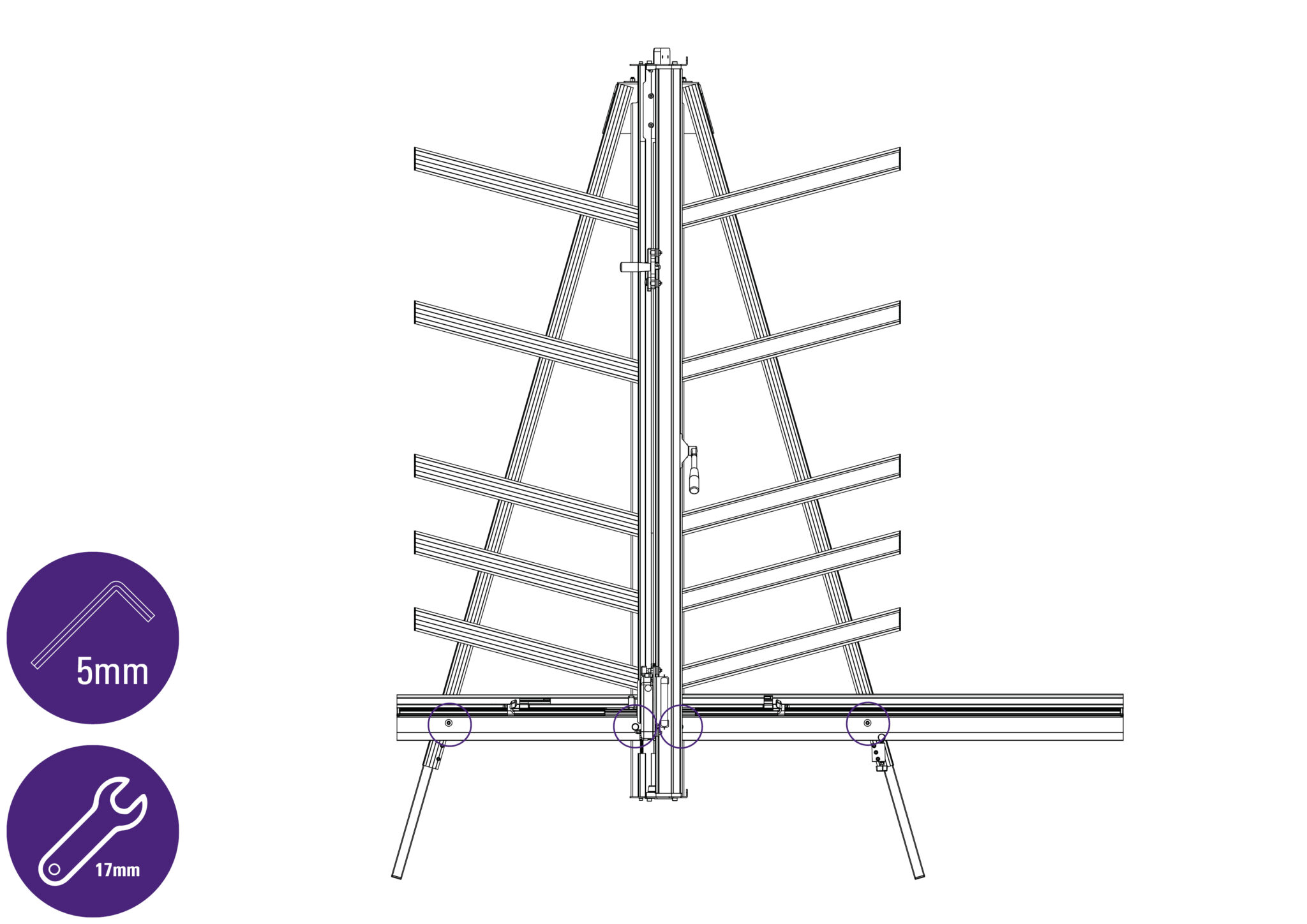
Tighten the four screws/nuts joining the Squaring Arm to the legs and the Main Body respectively, using a 5mm Allen (hex) key and a 17mm spanner once the squareness has been adjusted.
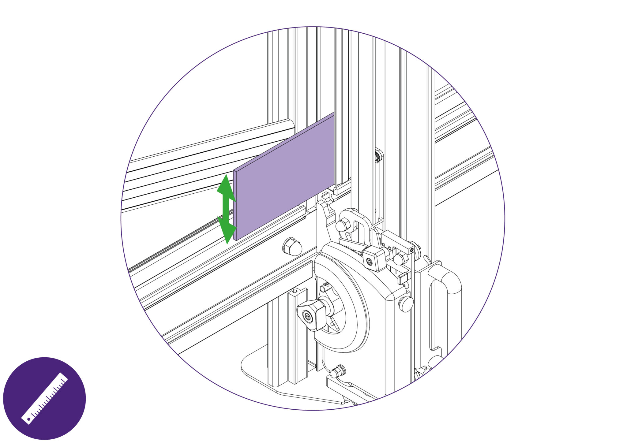
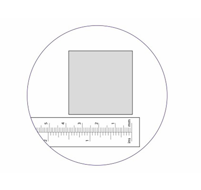
Take a small piece of board and accurately measure its’ height. Place the board on to the material channel of the Squaring Arm such that it lays over the groove where the scale is to be applied.
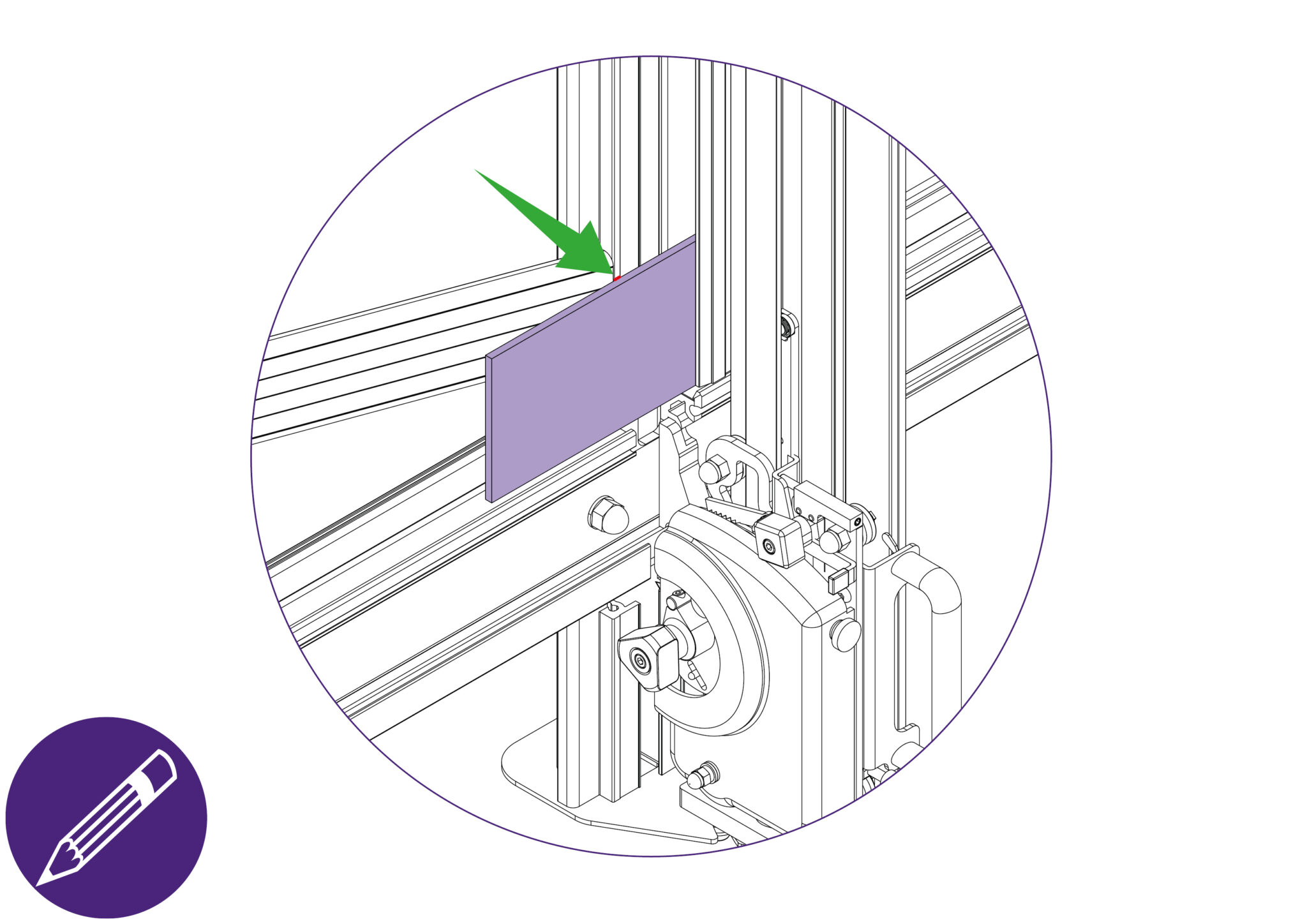
With a pencil, mark a fine line level with the top edge of the board adjacent to the groove.
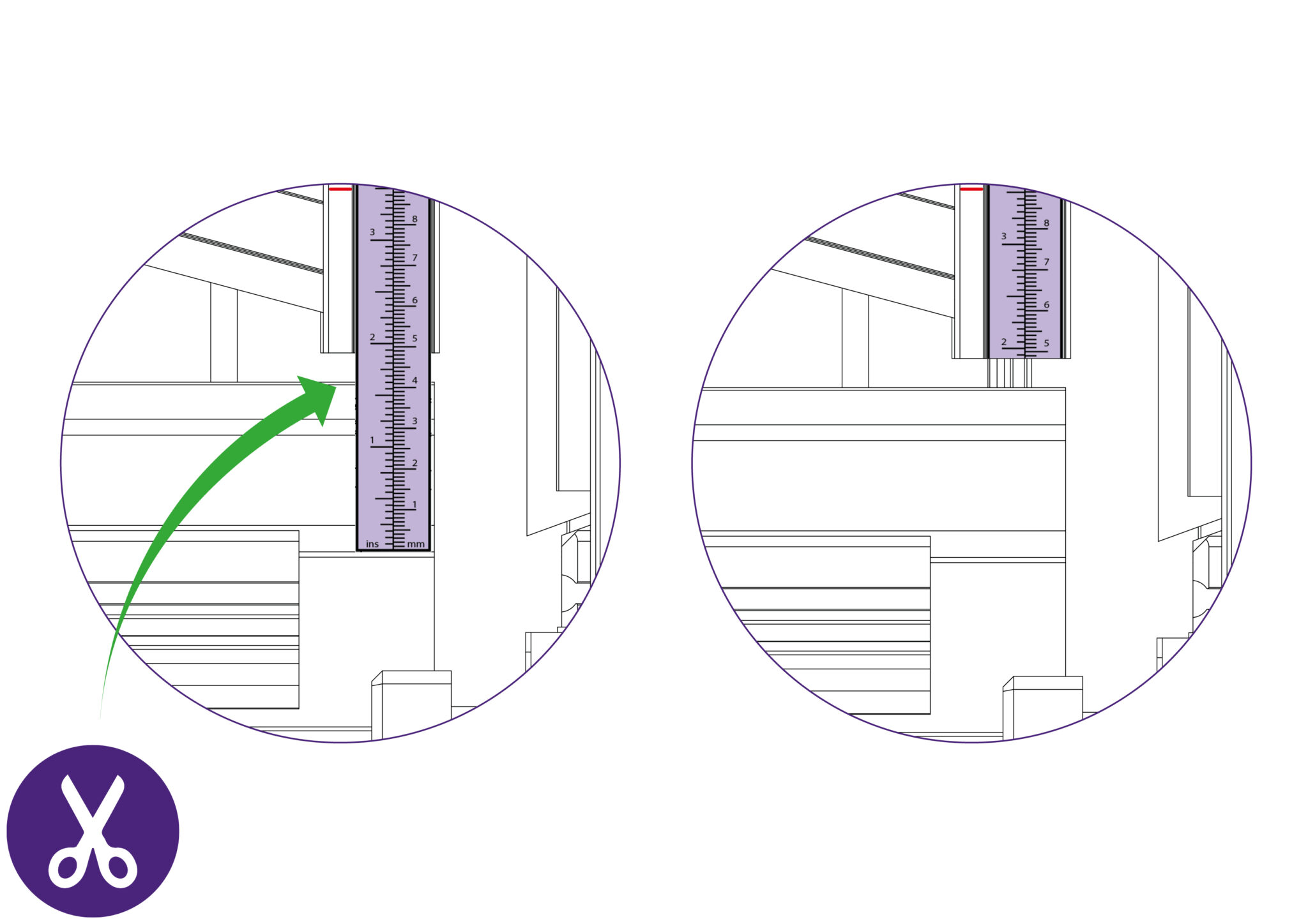
Remove the release paper from the Vertical scale and stick it in place within the groove, such that the pencil mark lines up with the measured dimension of the board. Trim any excess from the ends.
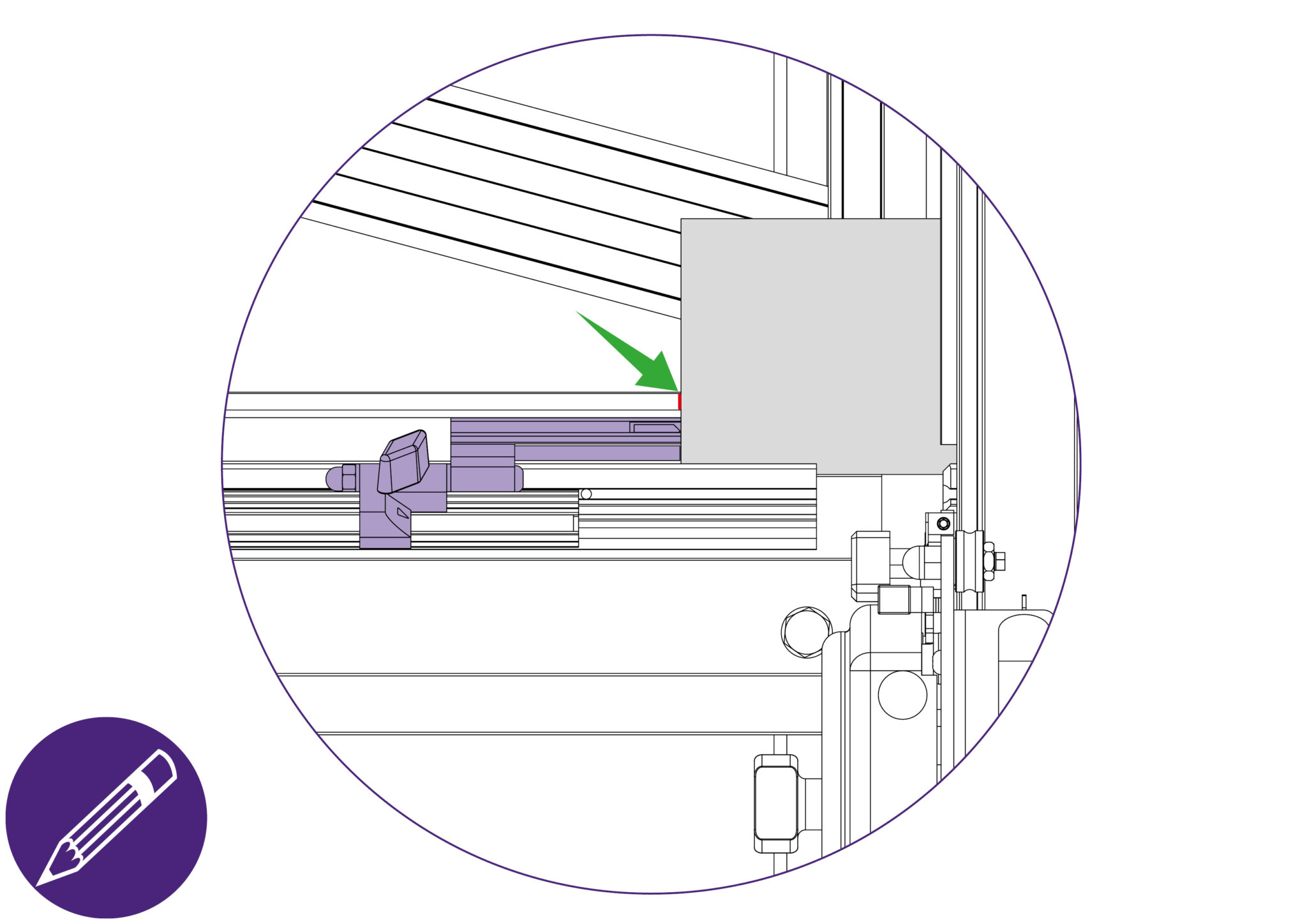
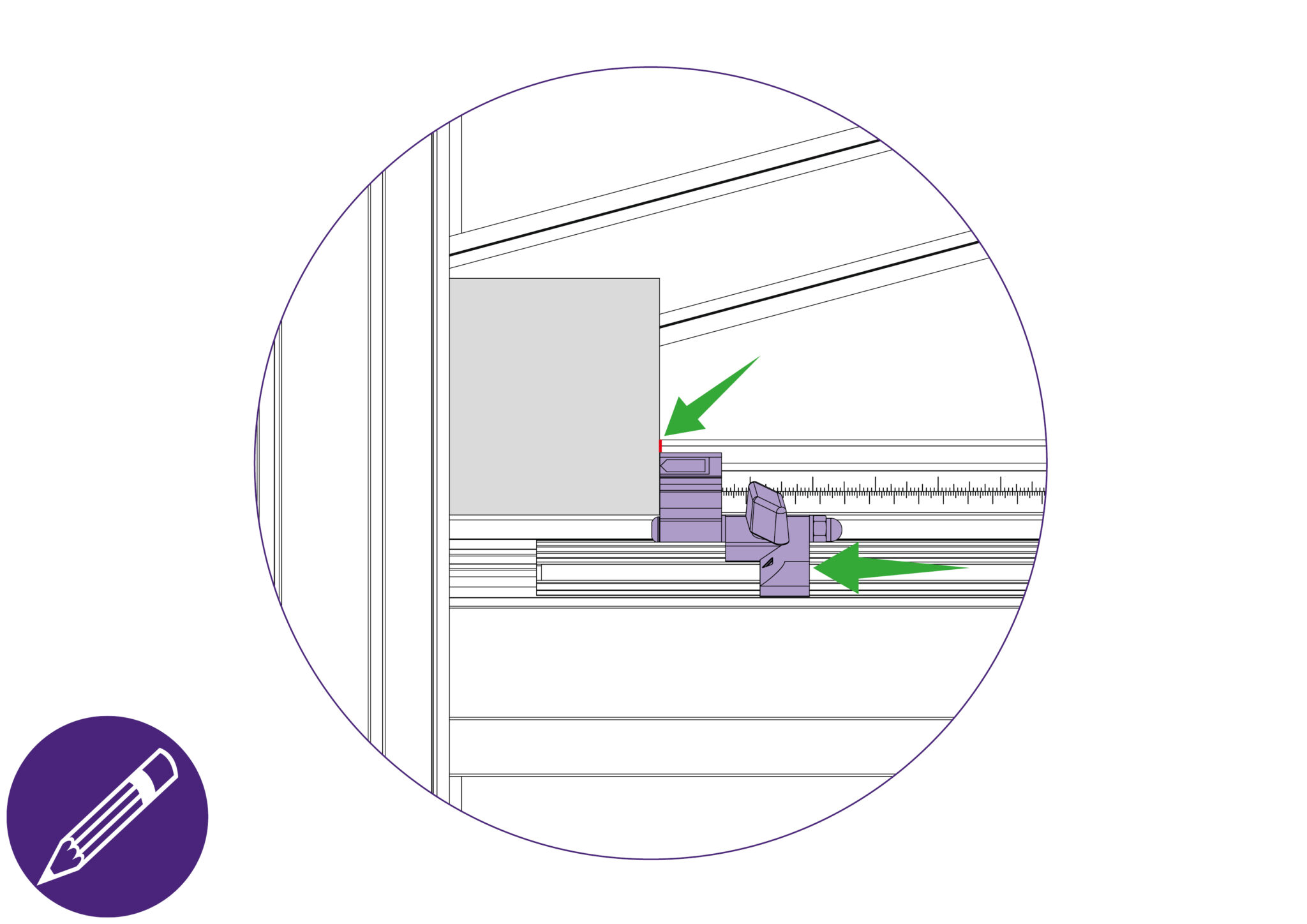
Place a piece of board in the machine and apply the clamp. Mark the top edge of the Squaring Arm with a pencil (this can be removed with an eraser later) adjacent to the left hand edge of the board.
Cut the board and measure the width of the cut.
Peel the backing tape from the scale (part N) and place it in its groove so the pencil mark lines up with the measured dimension of the board. Trim the right and left hand end of the scale accordingly.
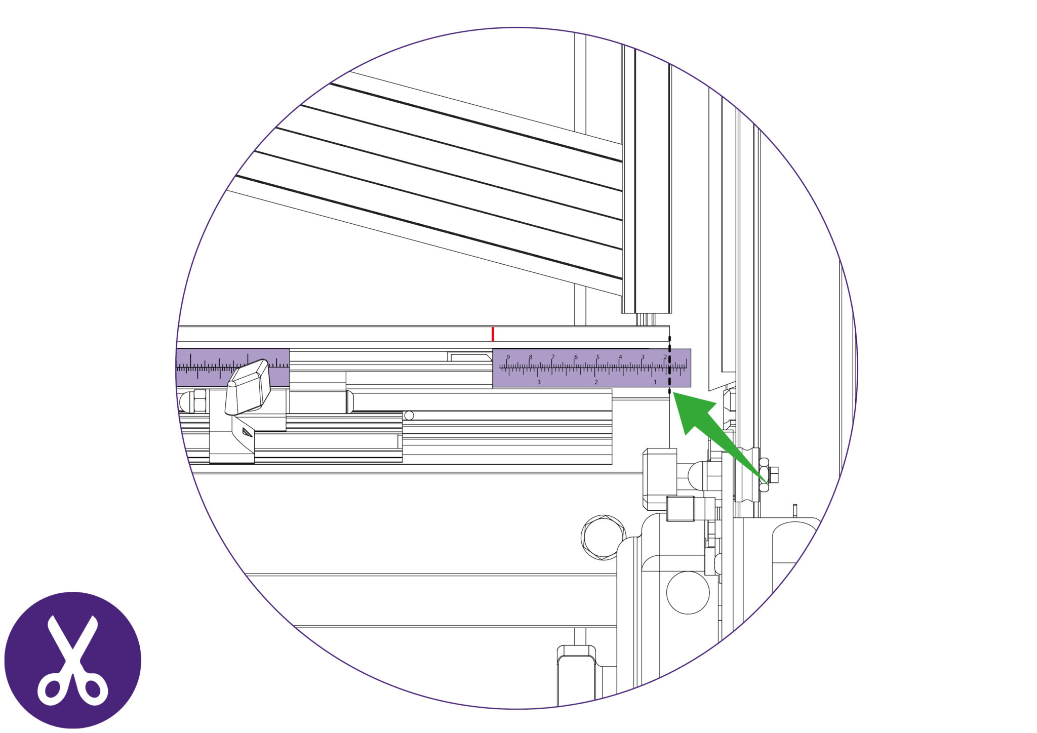
Clamp another piece of board in the machine and move the production stop up to it.
Cut the board and measure the width of the cut.
If the width of the cut board does not match the scale measurement that aligns with production stop, calibration would be required.
Otherwise, proceed to “Calibrating the Easy Measuring Scale”>.
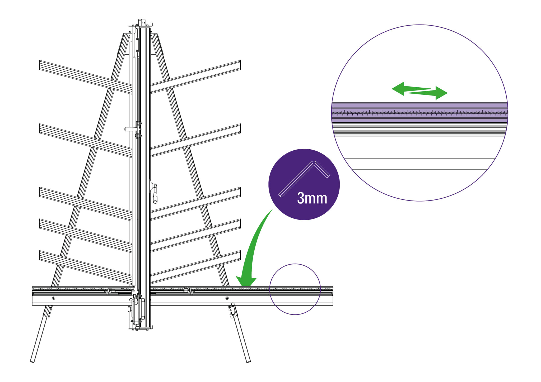
The top edge of the Squaring Arm slides left to right to enable calibration. Use the 3mm Allen (hex) key to remove the screw in the back of the Squaring Arm.
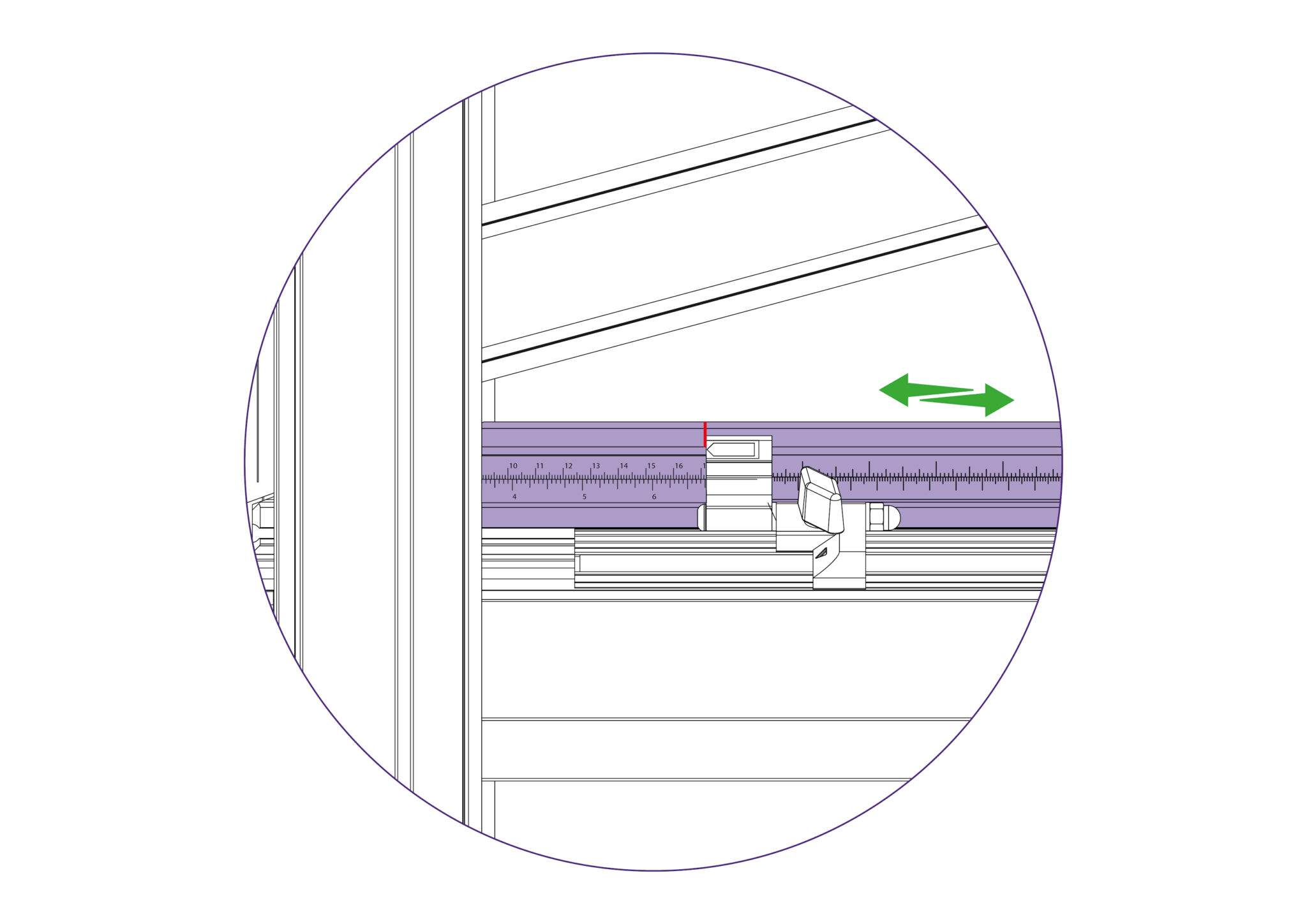
Adjust the sliding scale so that the production stop indicates the measured size of the board.
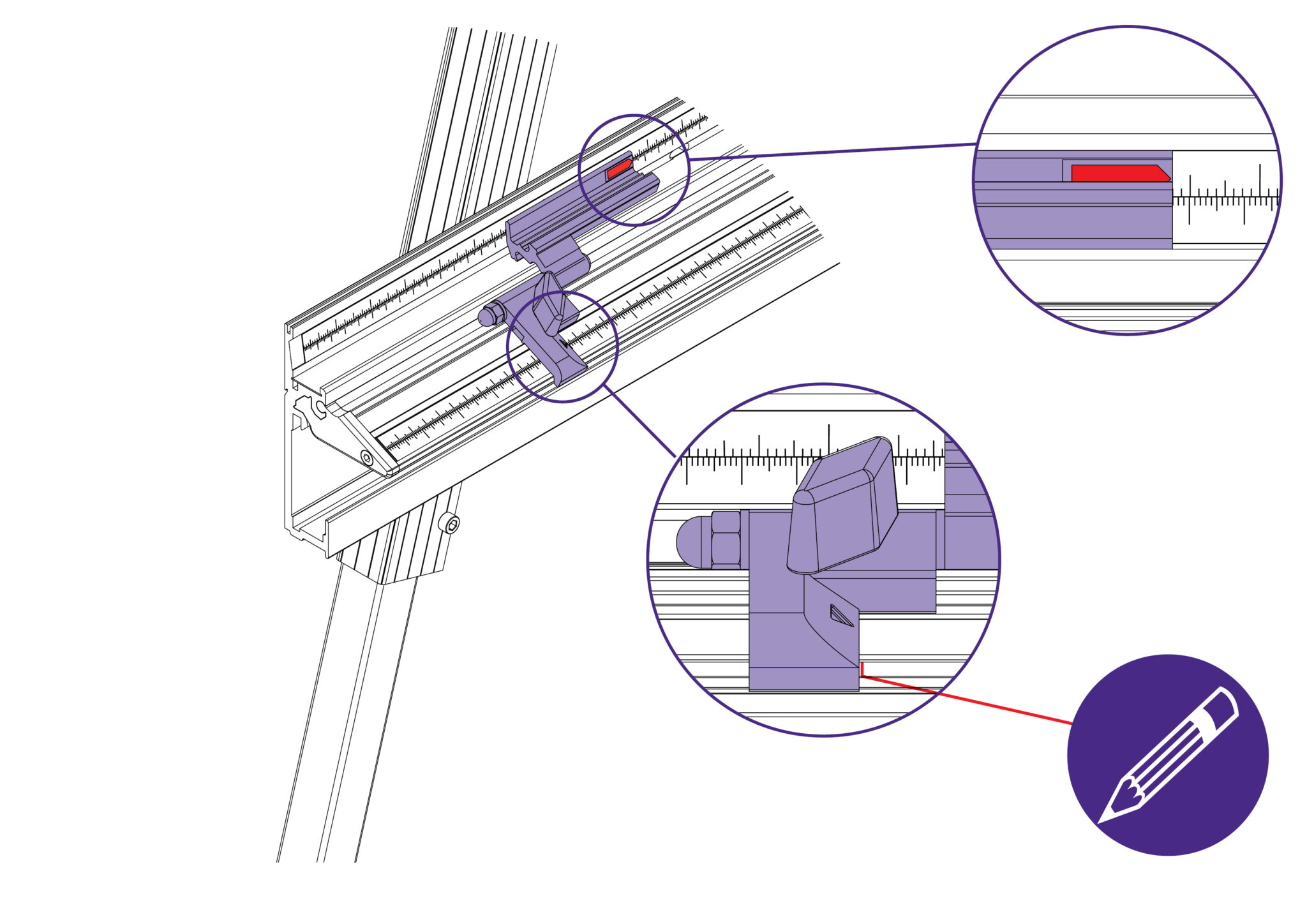
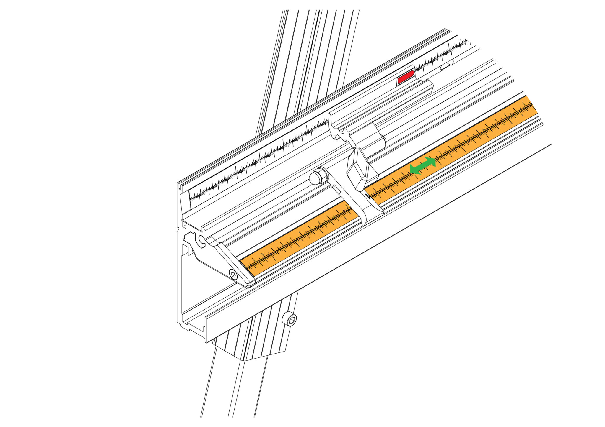
Align the material stop with a measurement on the squaring arm and make note of this measurement. Make a pencil mark on the aluminium as shown.
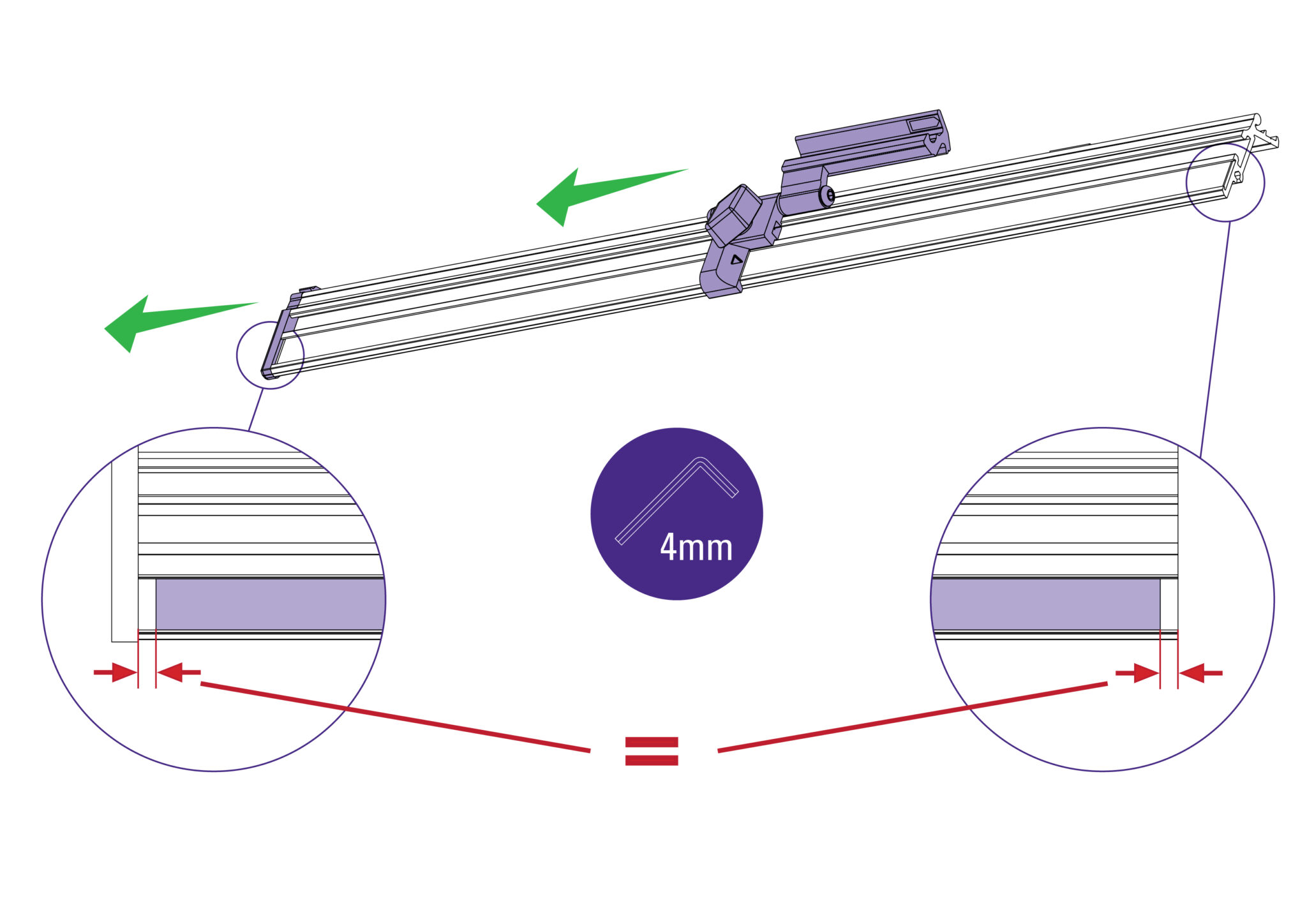
Remove end cap using 4mm Allen (hex) key. Remove the measuring stop. Check the steel strip for the measuring tape is centered along its length.
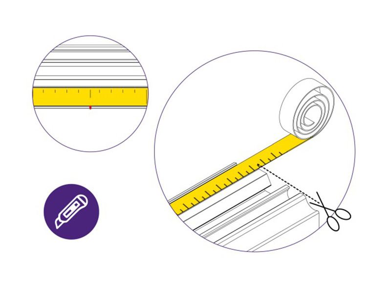
Apply the scale to the steel strip so the recorded measurement on the tape aligns with the pencil mark. Carefully trim the excess tape at each end of the steel strip.
Replace the measuring stop and the end cap.
Fine adjustments can be made by sliding the steel measuring strip.
Repeat process on right hand side.
Note: It would be useful to cover the “Get to know your cutter”> sections in the User Manual before proceeding with the following steps.
Place the board on the machine vertically as shown and apply the clamp ensuring the bottom edge is in firm contact with the Squaring Arm.
Select the cutting blade on the Multi-Tool Cutting Head.
Cut into the top board to produce a cut approximately 3cm (1”) long. Disengage the cutter using the cutter release lever.
Lower the cutter and make a similar cut at the bottom of the board by pressing the blade through the board about 3cm (1″) from the bottom edge of the board.
Unclamp and turn the board around laterally (like the page in a book) and place it back in the machine so the same edge is still on the Squaring Arm, but do not clamp it.
Align and engage the blade so it enters the previous made cut at the bottom edge of the board. Now apply the clamp.
Raise the cutter to the top of the board, and if the machine is square the blade should enter the same cut as made previously. If not refer to Adjusting the squareness> to make the necessary
adjustment.
If it is square, continue to Calibrating the vertical scale>.
NOTE: Before making any adjustments carry out the squareness check as described in Checking the machine for squareness>
It is assumed that the board used for the test is still clamped in the machine. From the test results, determine if the last cut made in the top of the board is to the left or right of the previous cut.
Use a 5mm Allen (Hex) key to slacken the two screws joining the squaring arm to the two legs.
Use a 17mm spanner to slacken the left hand nut joining the Squaring Arm to the Main Body, and make sure the right hand nut is tight.
Release the clamp and position the board such that the blade is held in the cut on the bottom edge of the board. Press down on the board to make sure it is in good contact with the Squaring Arm.
Turn the squaring adjustment knob on the right hand leg in the direction described next, dependent upon the position of the top two cuts.
If the second cut is to the right of the first cut, turn the adjustment screw clockwise when viewed from underneath.
If the second cut is to the left of the first cut turn the adjustment screw counter-clockwise when viewed from underneath.
The adjustment screw should be incrementally turned so that when the blade is moved to the top of the board it cuts between two existing cuts. Make sure that when assessing the location of the cut the Squaring Arm has good contact with the material being used.
Tighten the four screws/nuts joining the Squaring Arm to the legs and the Main Body respectively, using a 5mm Allen (hex) key and a 17mm spanner once the squareness has been adjusted.
Take a small piece of board and accurately measure its’ height. Place the board on to the material channel of the Squaring Arm such that it lays over the groove where the scale is to be applied.
With a pencil, mark a fine line level with the top edge of the board adjacent to the groove.
Remove the release paper from the Vertical scale and stick it in place within the groove, such that the pencil mark lines up with the measured dimension of the board. Trim any excess from the ends.
Place a piece of board in the machine and apply the clamp. Mark the top edge of the Squaring Arm with a pencil (this can be removed with an eraser later) adjacent to the left hand edge of the board.
Cut the board and measure the width of the cut.
Peel the backing tape from the scale (part N) and place it in its groove so the pencil mark lines up with the measured dimension of the board. Trim the right and left hand end of the scale accordingly.
Clamp another piece of board in the machine and move the production stop up to it.
Cut the board and measure the width of the cut.
If the width of the cut board does not match the scale measurement that aligns with production stop, calibration would be required.
Otherwise, proceed to “Calibrating the Easy Measuring Scale”>.
The top edge of the Squaring Arm slides left to right to enable calibration. Use the 3mm Allen (hex) key to remove the screw in the back of the Squaring Arm.
Adjust the sliding scale so that the production stop indicates the measured size of the board.
Align the material stop with a measurement on the squaring arm and make note of this measurement. Make a pencil mark on the aluminium as shown.
Remove end cap using 4mm Allen (hex) key. Remove the measuring stop. Check the steel strip for the measuring tape is centered along its length.
Apply the scale to the steel strip so the recorded measurement on the tape aligns with the pencil mark. Carefully trim the excess tape at each end of the steel strip.
Replace the measuring stop and the end cap.
Fine adjustments can be made by sliding the steel measuring strip.
Repeat process on right hand side.
Ⓒ Keencut 2020 | Baird Rd, Corby NN17 5ZA UK | Contattaci |
Creato da DeType | Privacy | Clausola di esonero sito web
Politica dei resi |
Seguici