
Excalibur 3S installation manual – Squaring and Calibration
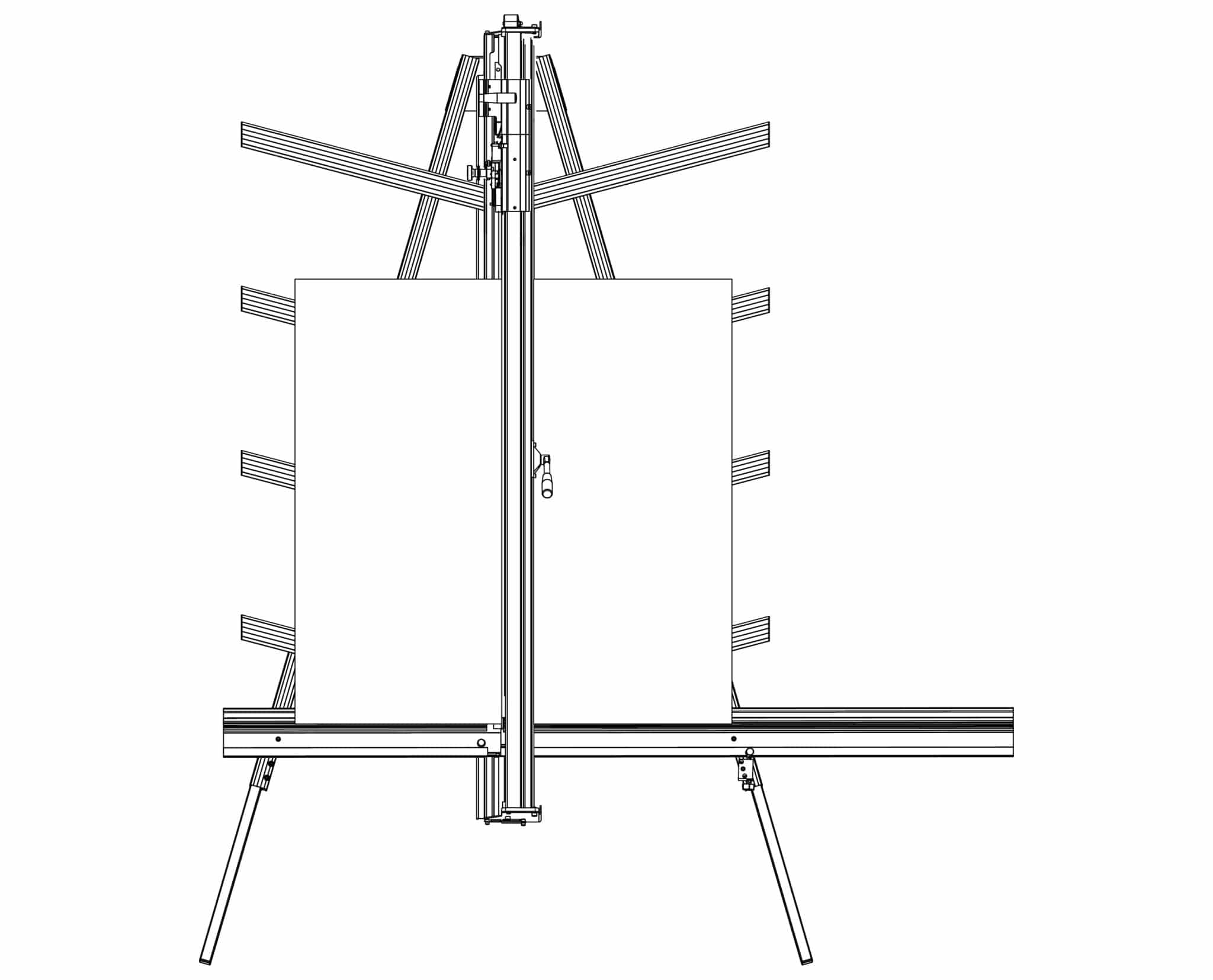
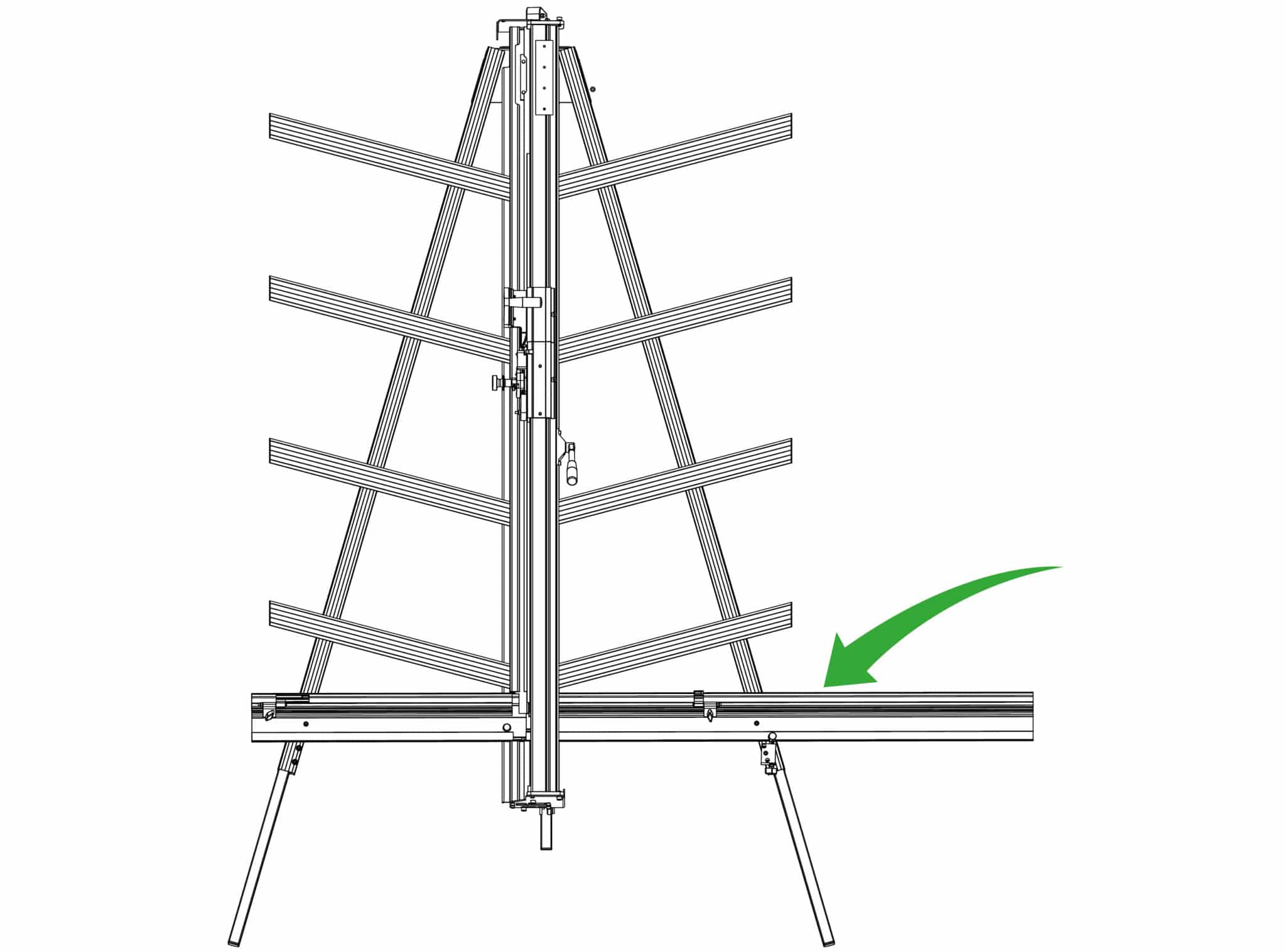
Place the board on the machine vertically as shown and apply the clamp ensuring the bottom edge is in firm contact with the squaring arm.
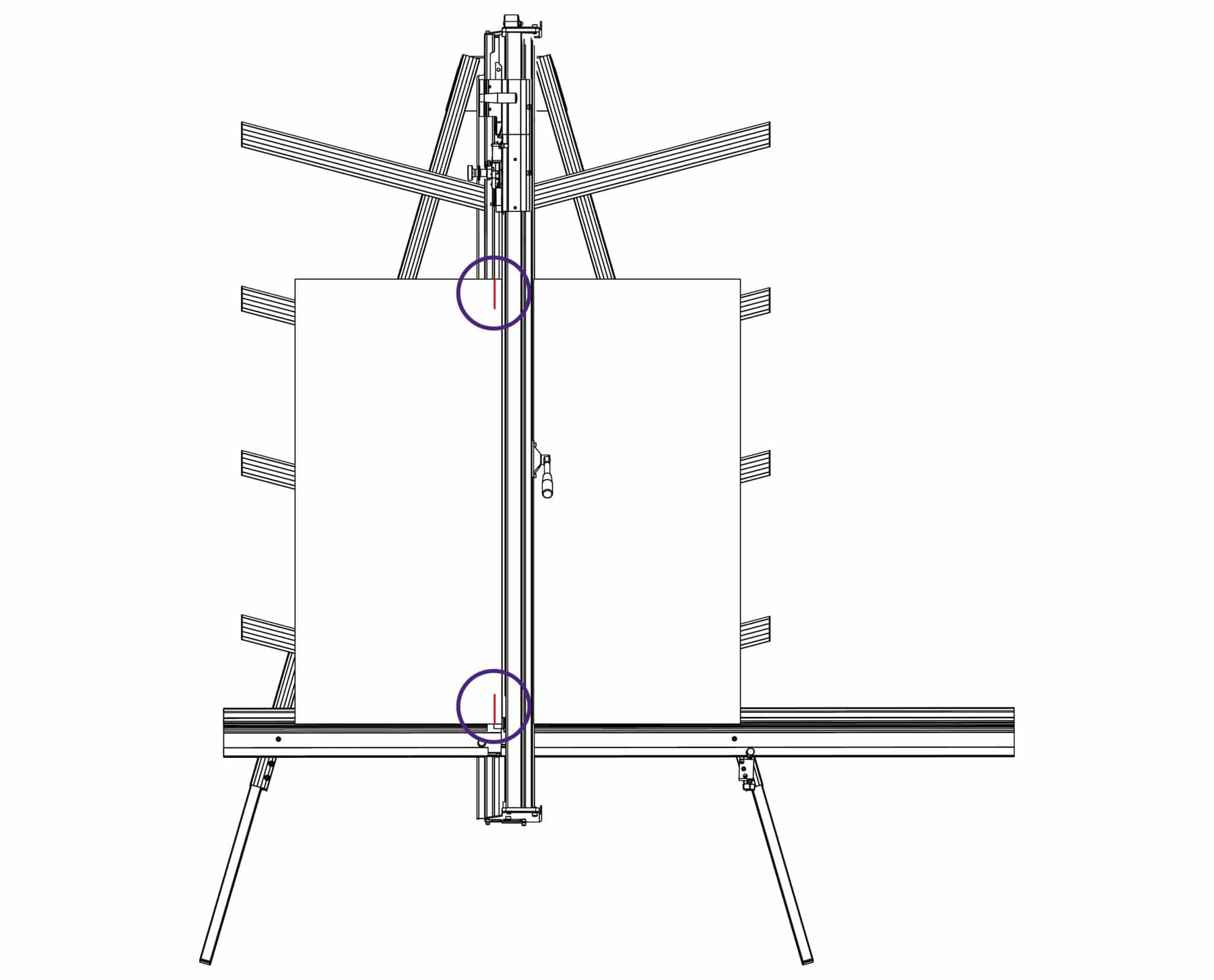
Select the cutting blade on the lower cutting head (see Using the multi-tool cutter head & counterbalance >). Cut into the top board to produce a cut approximately 3cm (1”) long. Disengage the cutter using the cutter release lever. Lower the cutter and make a similar cut at the bottom of the board.
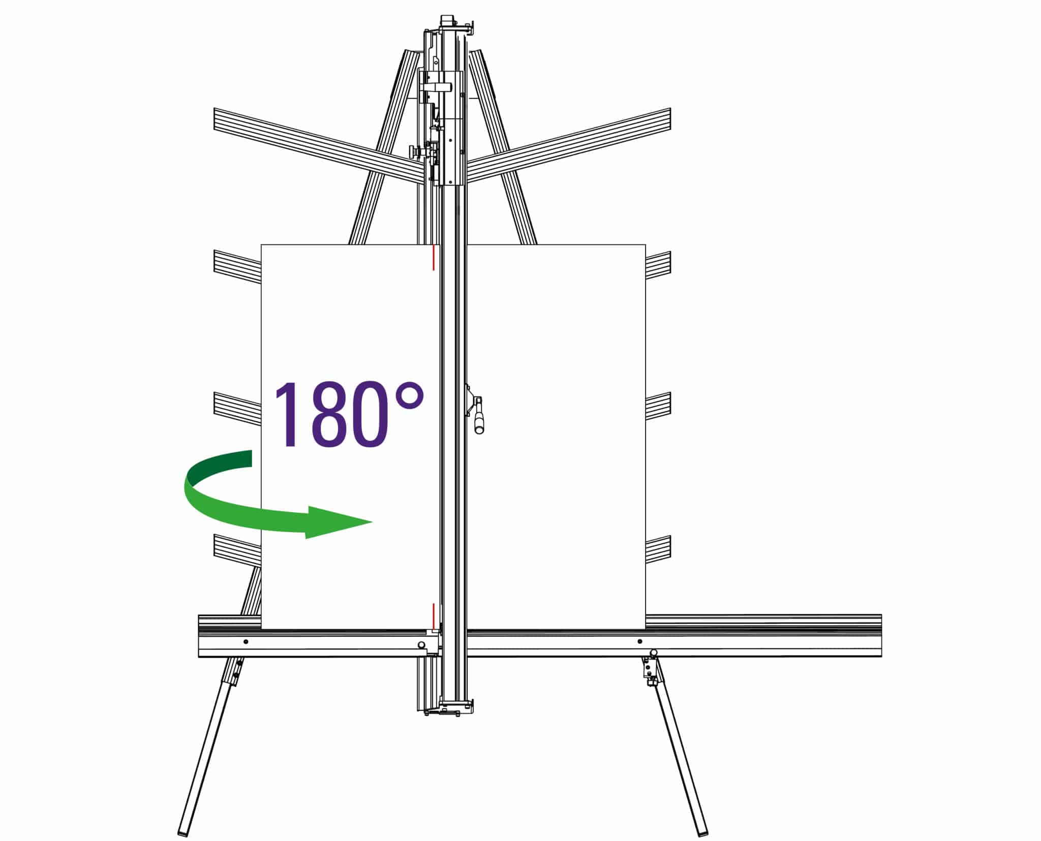
Unclamp and turn the board around (like the page in a book) and place it back in the machine so the same edge is still on the squaring arm but do not clamp it. Align and engage the blade so it enters the previous made cut at the bottom edge of the board. Now apply the clamp.
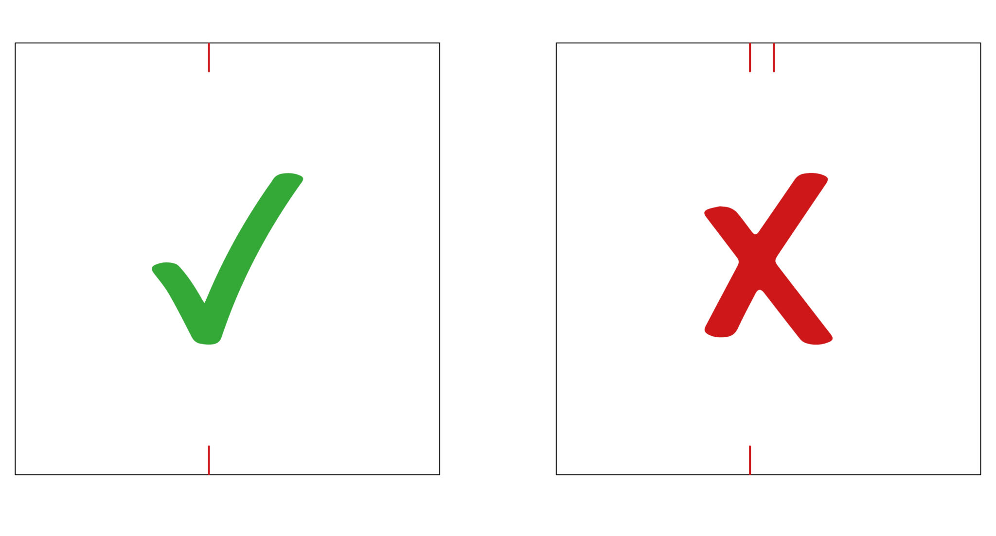
Raise the cutter to the top of the board, if the machine is square the blade should enter
the same cut as made previously. If not refer to Adjusting the squareness> to make the necessary
adjustment.
If it is square, continue to Calibrating the vertical scale>
NOTE: Before making any adjustments carry out the squareness check as described in Checking the machine for squareness>
It is assumed that the board used for the test is still clamped in the machine. From the test results determine if the last cut made in the top of the board is to the left or right of the previous cut.
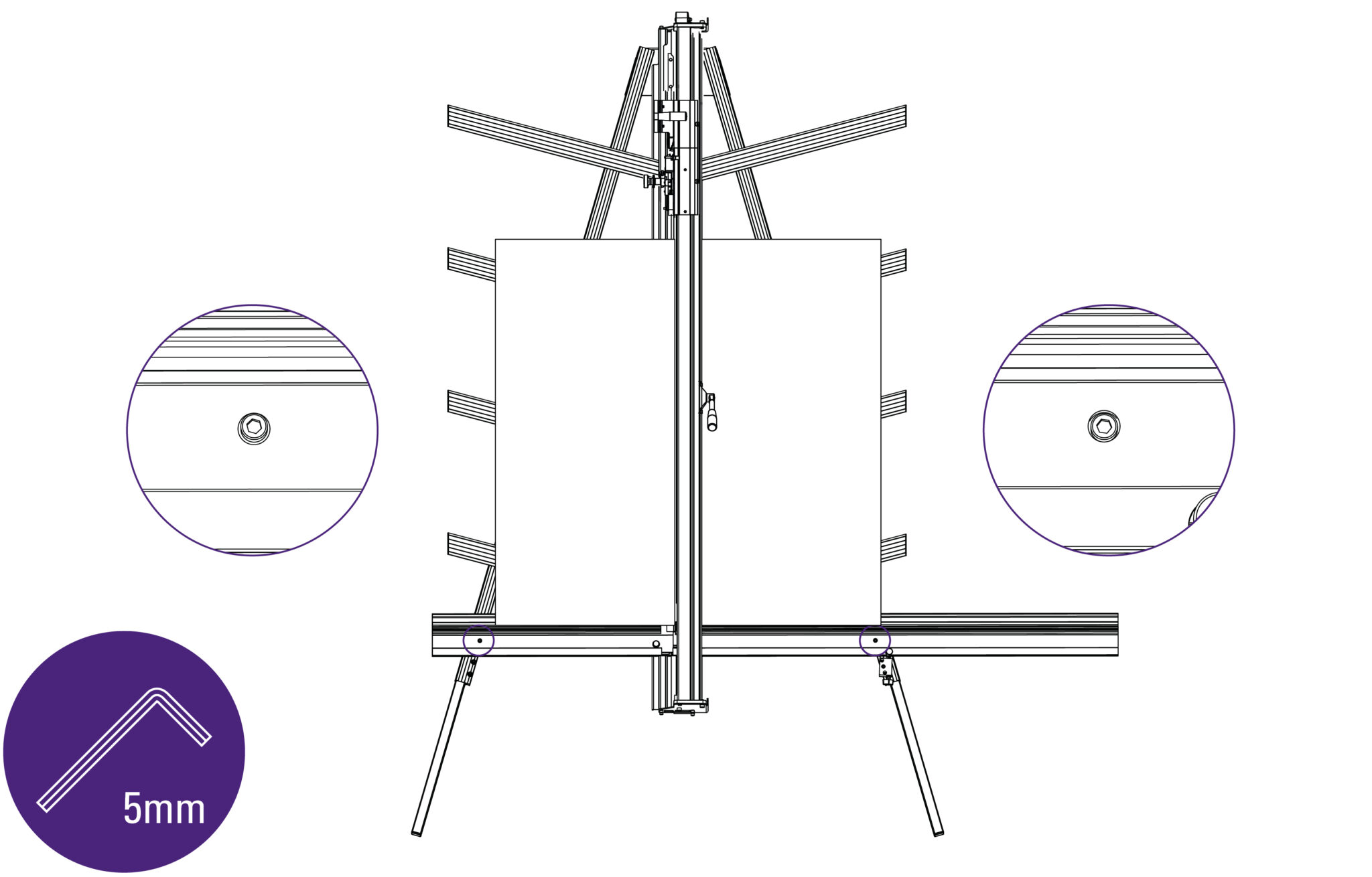
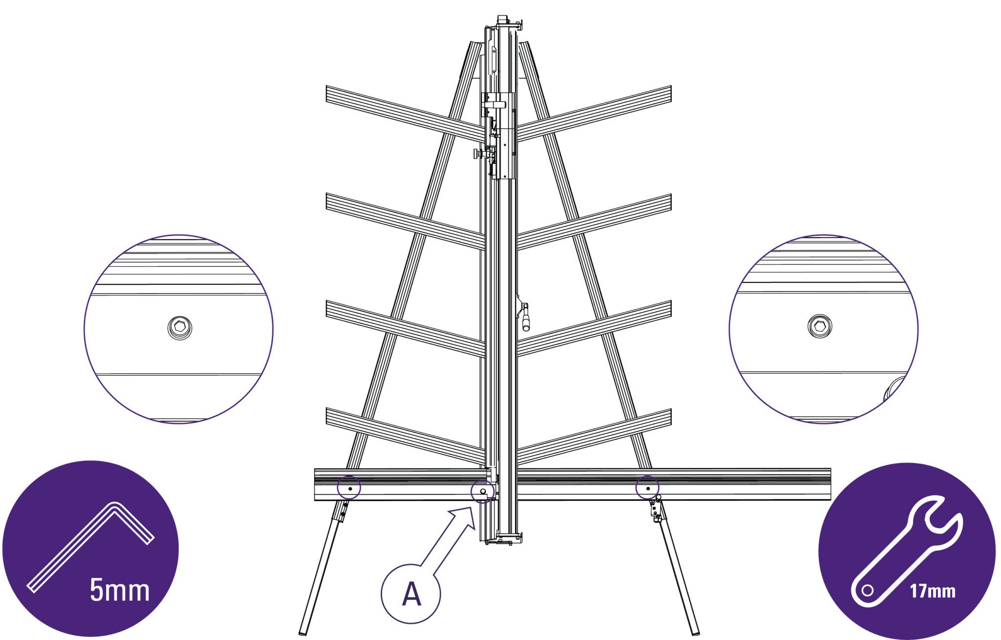
Use a 5mm Allen (Hex) key to slacken the two screws joining the squaring arm to the two legs.
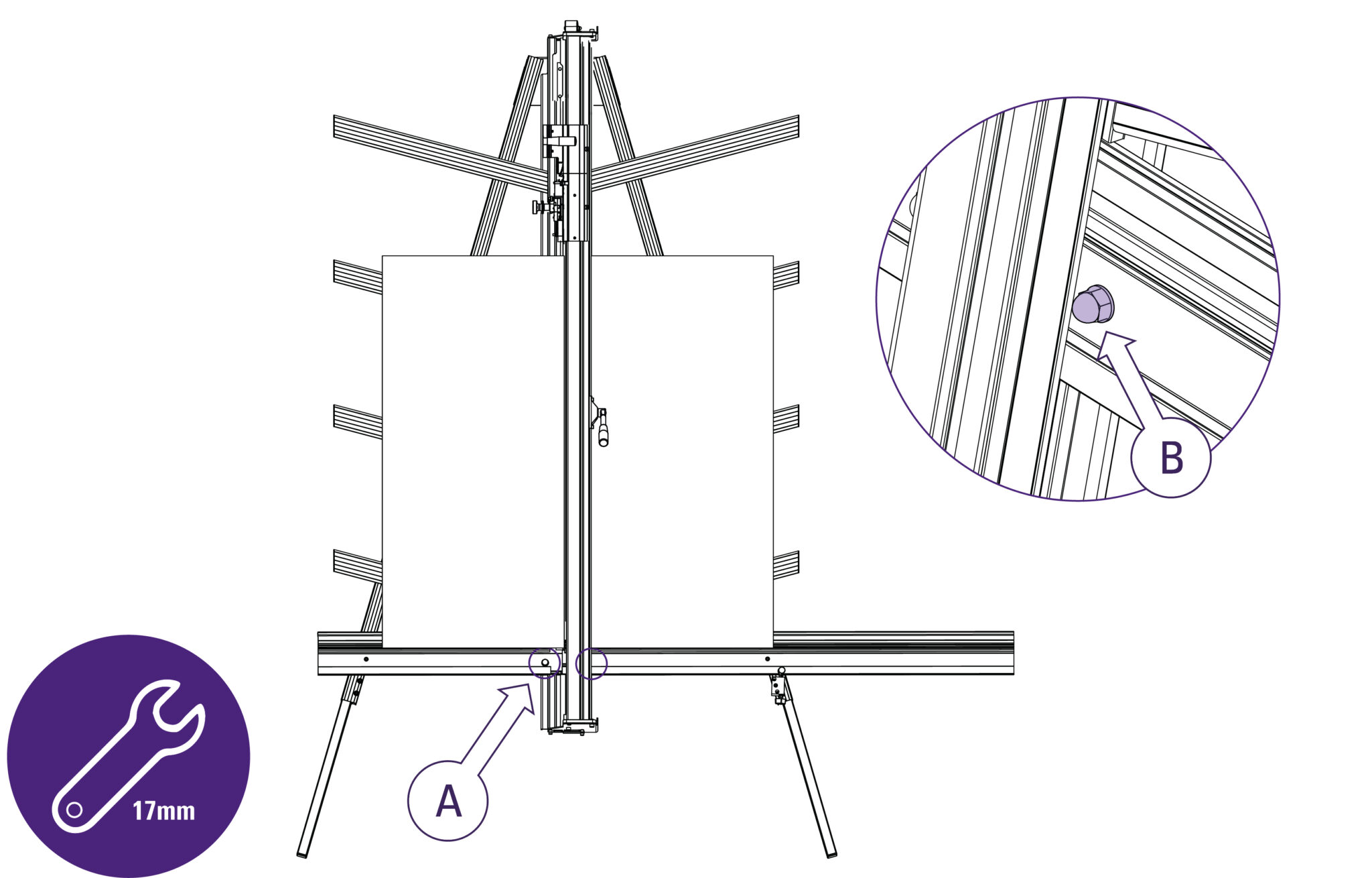
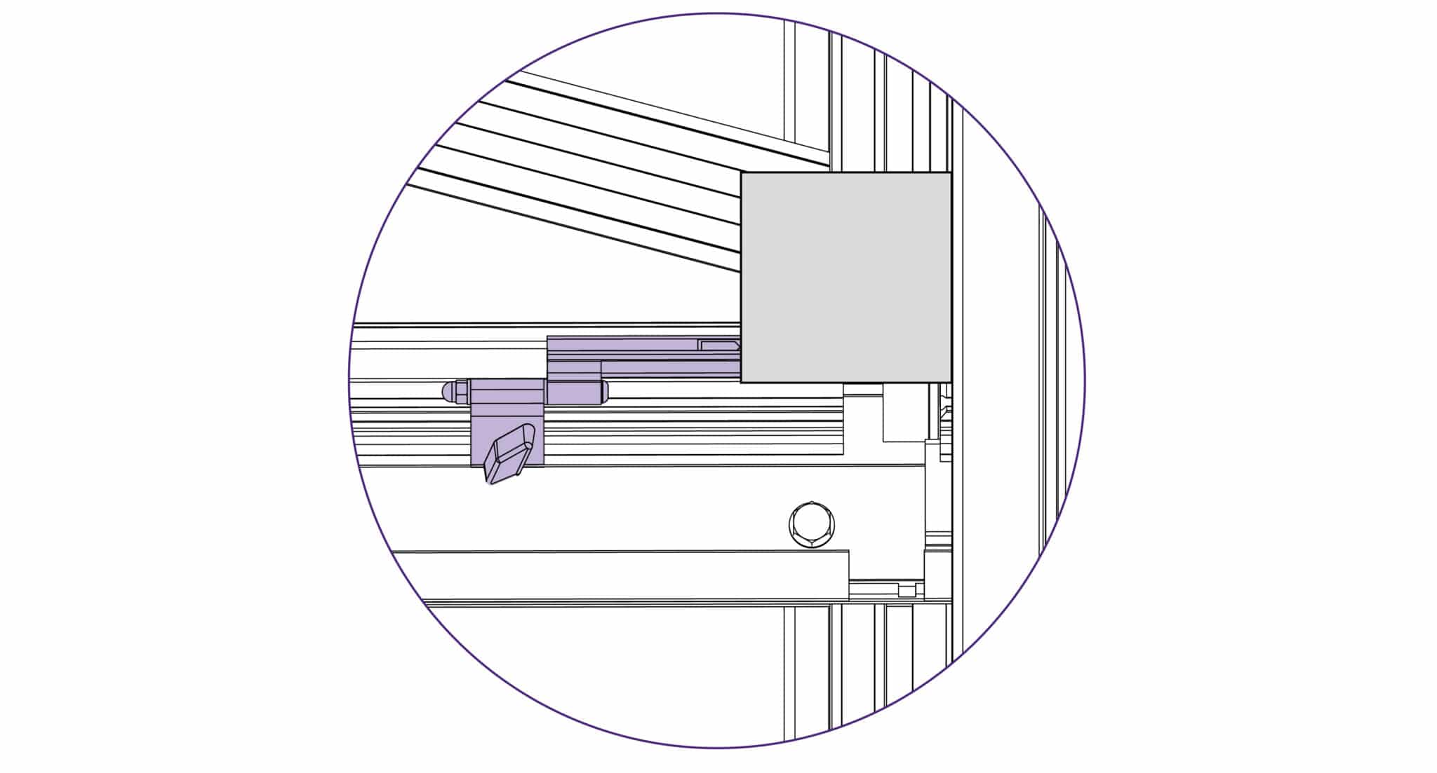
Use a 17mm spanner to slacken the left hand nut (A) joining the squaring arm to the main body, make sure the right hand nut (B) is tight
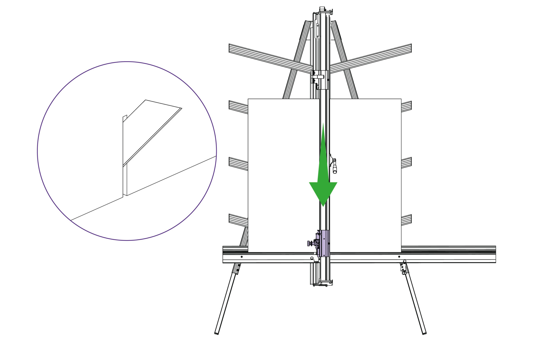
Release the clamp and position the board such that the blade is held in the cut on the bottom edge of the board. Press down on the board to make sure it is in good contact with the squaring arm.
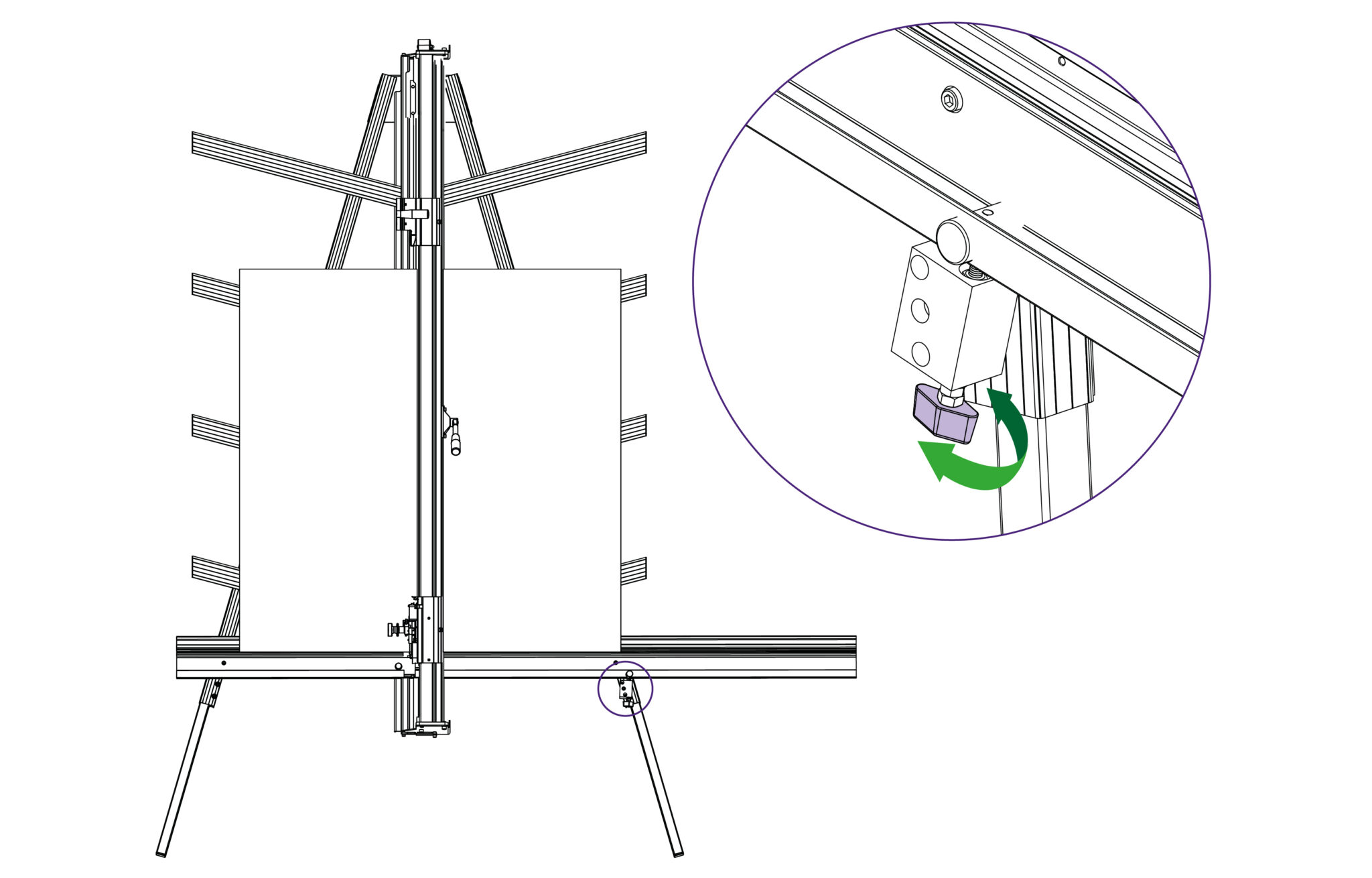
Turn the squaring adjustment knob on the right hand leg in the direction described next dependent upon the position of the top two cuts.
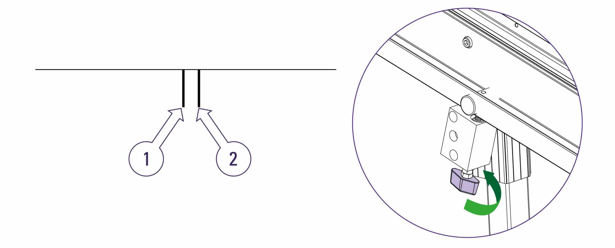
If the second cut is to the right of the first cut turn the adjustment screw clockwise when viewed from underneath.
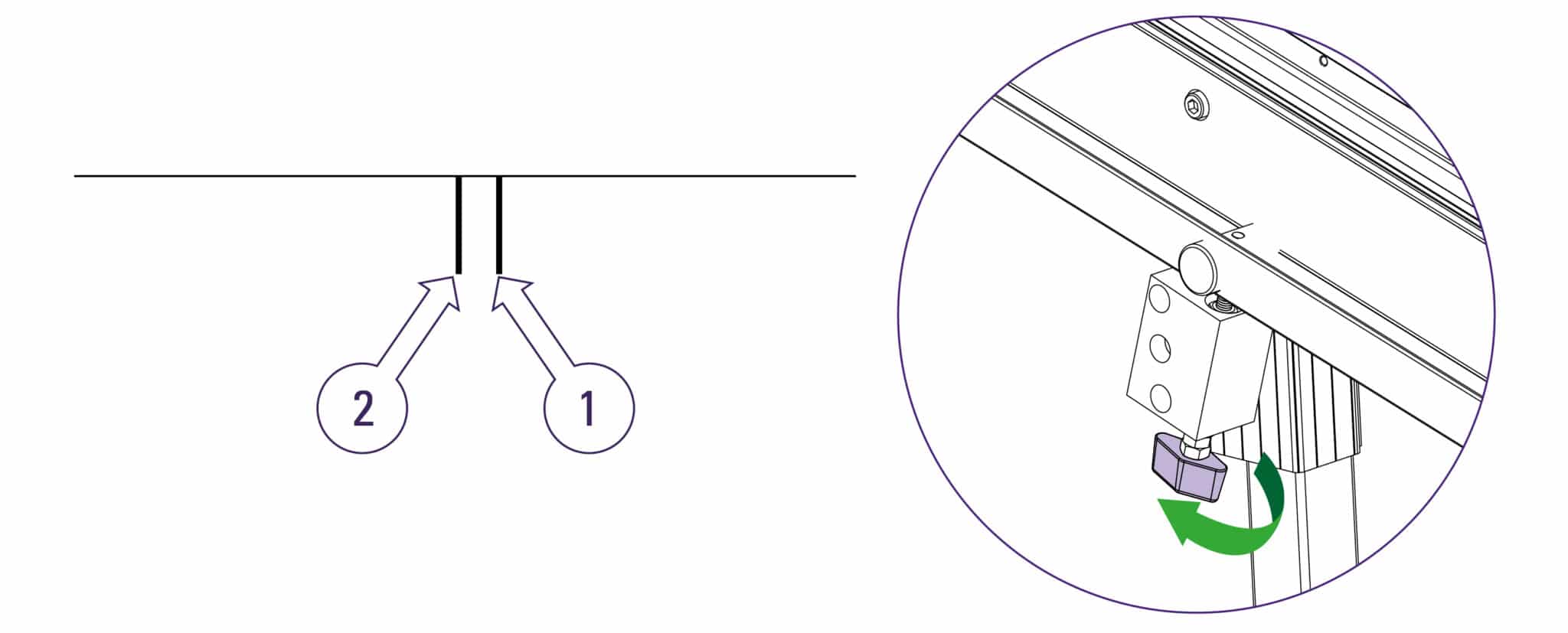
If the second cut is to the left of the first cut turn the adjustment screw counter-clockwise when viewed from underneath.

The adjustment screw should be moved so that when the blade is moved to the top of the board it cuts between two existing cuts, the plastic sightline fixed to the edge of the clamp gives an indication where the machine is going to cut. Make sure that when assessing the location of the cut that the clamp has good contact with the material being used.
Repeat the squareness check. Tighten the screws using a 5mm Allen (hex) key and a 17mm spanner to tighten nut A once the squareness has been adjusted.
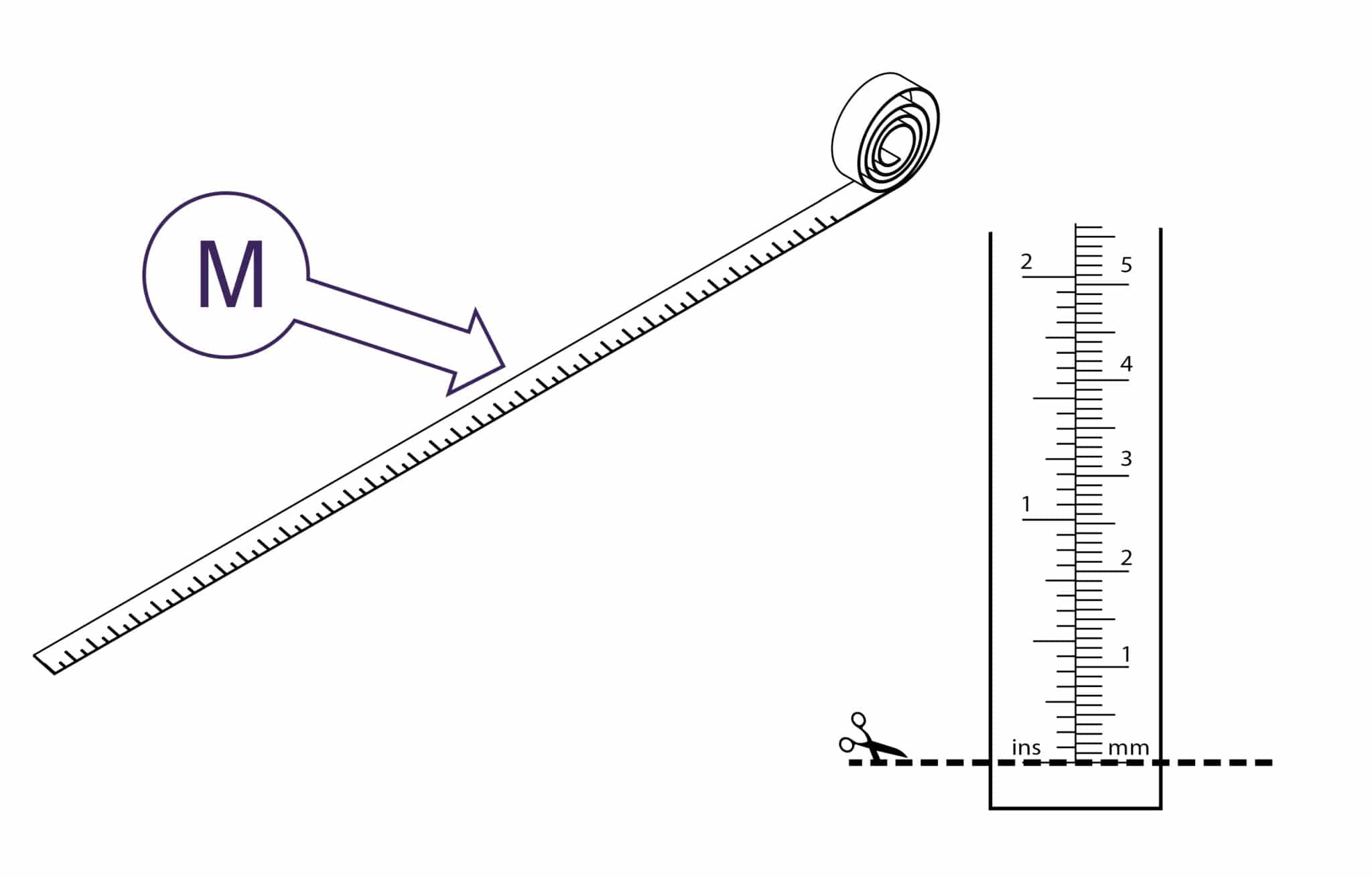
Trim the bottom of the scale at zero with scissors
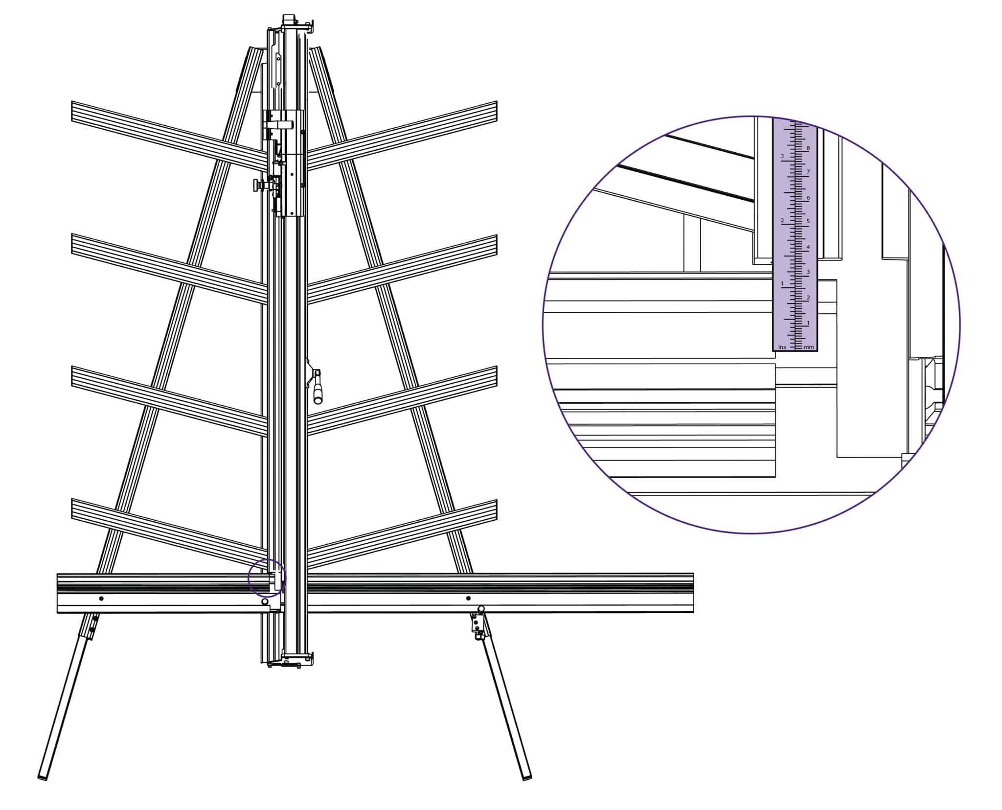
Remove the paper backing tape and carefully place the rule adjacent to its groove in the main body and with the zero end resting inside the material channel of the squaring arm. When aligned stick the rule in its groove.
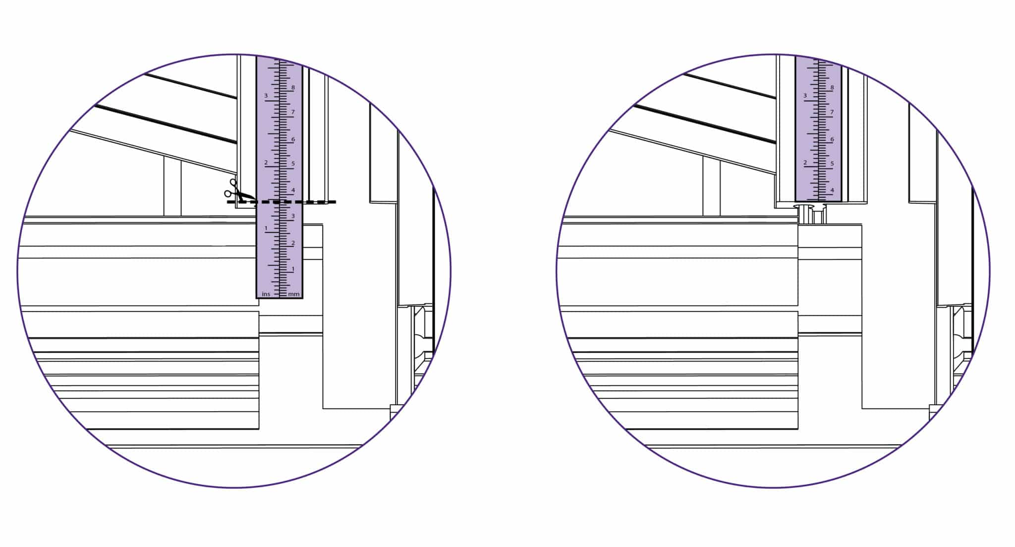
Again trim the rule at the bottom end as shown.
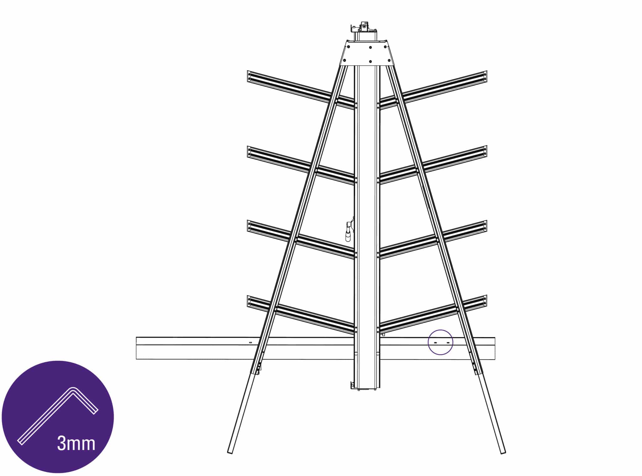
The top edge of the squaring arm slides left to right to enable calibration. Use the 3mm Allen (hex) key to loosen the screw in the back of the squaring arm if adjustment is necessary.
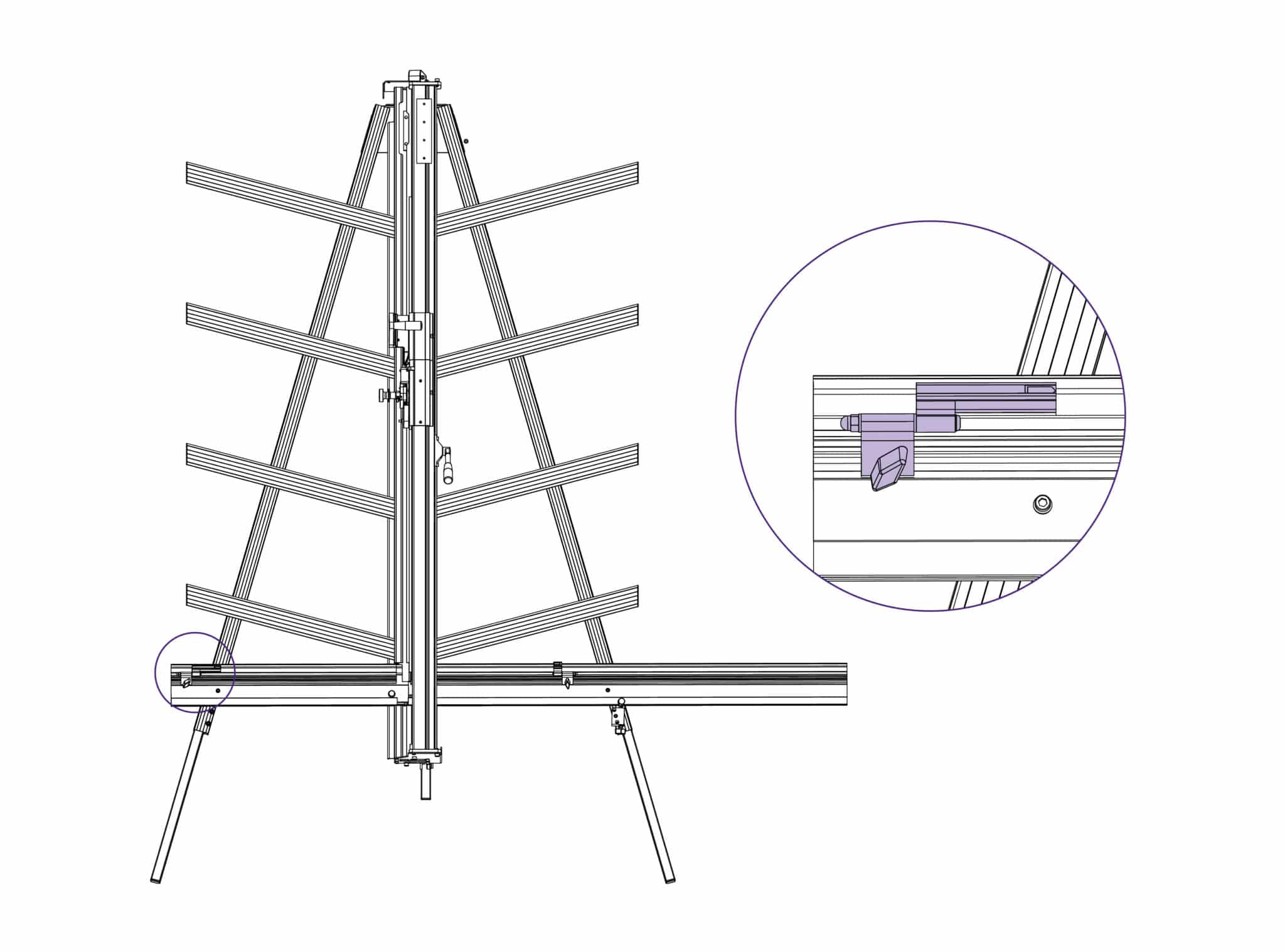
Slide the production stop onto the outside edge of the squaring arm as shown.
Clamp a piece of card in the machine and move the production stop to it.
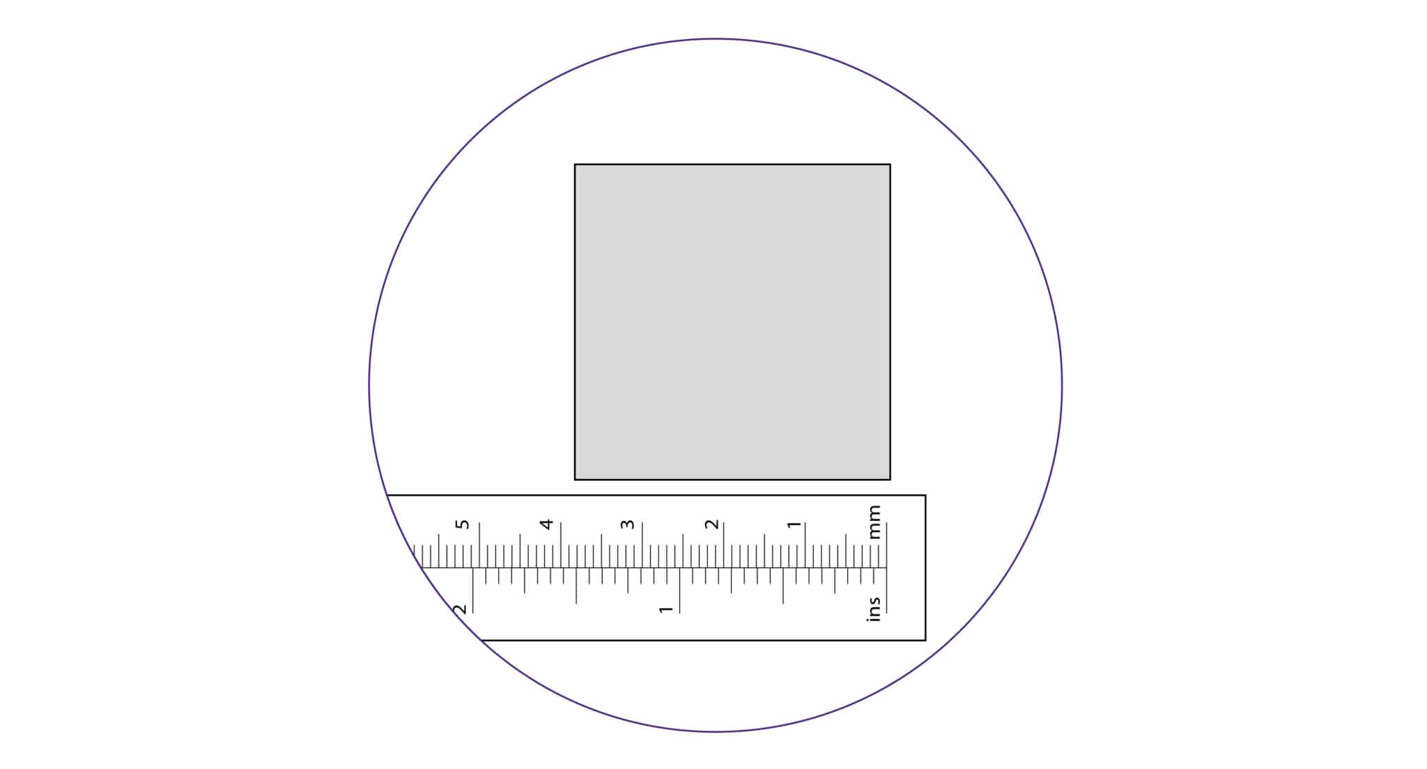
Cut the card and measure, adjust the sliding scale so that the production stop indicates the measured size.
Repeat the process for the other side of the machine.
Place the board on the machine vertically as shown and apply the clamp ensuring the bottom edge is in firm contact with the squaring arm.
Select the cutting blade on the lower cutting head (see Using the multi-tool cutter head & counterbalance >). Cut into the top board to produce a cut approximately 3cm (1”) long. Disengage the cutter using the cutter release lever. Lower the cutter and make a similar cut at the bottom of the board.
Unclamp and turn the board around (like the page in a book) and place it back in the machine so the same edge is still on the squaring arm but do not clamp it. Align and engage the blade so it enters the previous made cut at the bottom edge of the board. Now apply the clamp.
Raise the cutter to the top of the board, if the machine is square the blade should enter
the same cut as made previously. If not refer to Adjusting the squareness> to make the necessary
adjustment.
If it is square, continue to Calibrating the vertical scale>
NOTE: Before making any adjustments carry out the squareness check as described in Checking the machine for squareness>
It is assumed that the board used for the test is still clamped in the machine. From the test results determine if the last cut made in the top of the board is to the left or right of the previous cut.
Use a 5mm Allen (Hex) key to slacken the two screws joining the squaring arm to the two legs.
Use a 17mm spanner to slacken the left hand nut (A) joining the squaring arm to the main body, make sure the right hand nut (B) is tight
Release the clamp and position the board such that the blade is held in the cut on the bottom edge of the board. Press down on the board to make sure it is in good contact with the squaring arm.
Turn the squaring adjustment knob on the right hand leg in the direction described next dependent upon the position of the top two cuts.
If the second cut is to the right of the first cut turn the adjustment screw clockwise when viewed from underneath.
If the second cut is to the left of the first cut turn the adjustment screw counter-clockwise when viewed from underneath.
The adjustment screw should be moved so that when the blade is moved to the top of the board it cuts between two existing cuts, the plastic sightline fixed to the edge of the clamp gives an indication where the machine is going to cut. Make sure that when assessing the location of the cut that the clamp has good contact with the material being used.
Repeat the squareness check. Tighten the screws using a 5mm Allen (hex) key and a 17mm spanner to tighten nut A once the squareness has been adjusted.
Trim the bottom of the scale at zero with scissors
Remove the paper backing tape and carefully place the rule adjacent to its groove in the main body and with the zero end resting inside the material channel of the squaring arm. When aligned stick the rule in its groove.
Again trim the rule at the bottom end as shown.
The top edge of the squaring arm slides left to right to enable calibration. Use the 3mm Allen (hex) key to loosen the screw in the back of the squaring arm if adjustment is necessary.
Slide the production stop onto the outside edge of the squaring arm as shown.
Clamp a piece of card in the machine and move the production stop to it.
Cut the card and measure, adjust the sliding scale so that the production stop indicates the measured size.
Repeat the process for the other side of the machine.
Ⓒ Keencut 2020 | Baird Rd, Corby NN17 5ZA UK | Contattaci |
Creato da DeType | Privacy | Clausola di esonero sito web
Politica dei resi |
Seguici