


Excalibur 3S user guide
How to use this guide
Scroll down to view the guide.
You can expand and collapse sections using the + and – icons.
View PDF version >
Other support resources
Register your cutter to activate your guarantee >
Visit Keencut support centre >
Visit user forum >
Installation video >
Contact Keencut >
This User Guide for the Excalibur 3S gives advice on cutting techniques, care and maintenance of your machine.
Before using your machine make sure that you have installed and calibrated it correctly. Full details are in the Installation Manual.
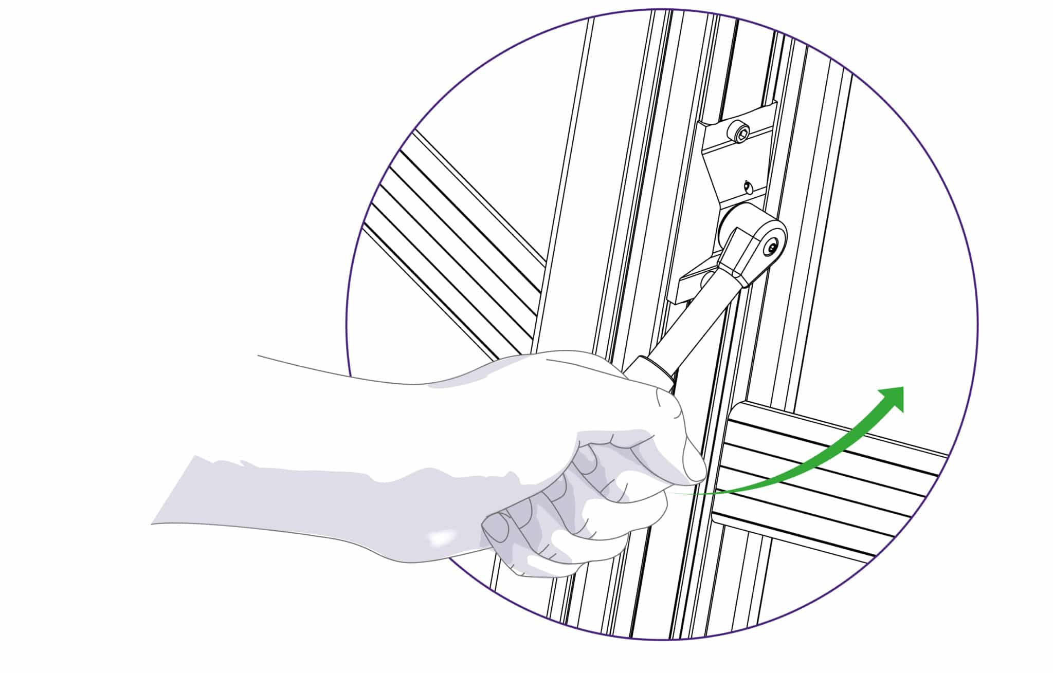
The clamping system enables the operator to control the grip pressure by means of an integral friction brake, that maintains the clamping force at the pressure applied by the operating lever. Soft materials can be held firmly without sustaining damage and solid materials are held rigidly without movement. By following the guidelines below it will help you to get the most from the machine.
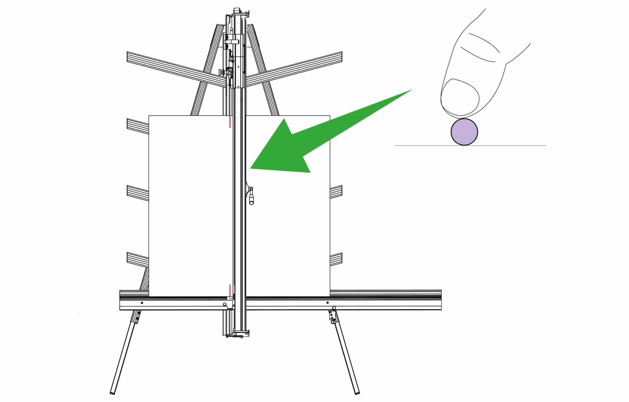
Soft materials such as Foamcore boards, lightweight card, etc. Use light to medium pressure. The underside of the clamp grips an area nearly 4cm (11/2”) wide with a non-marking sponge rubber
and reasonable force can be applied. If in doubt clamp a sample first with the good surface facing outwards.
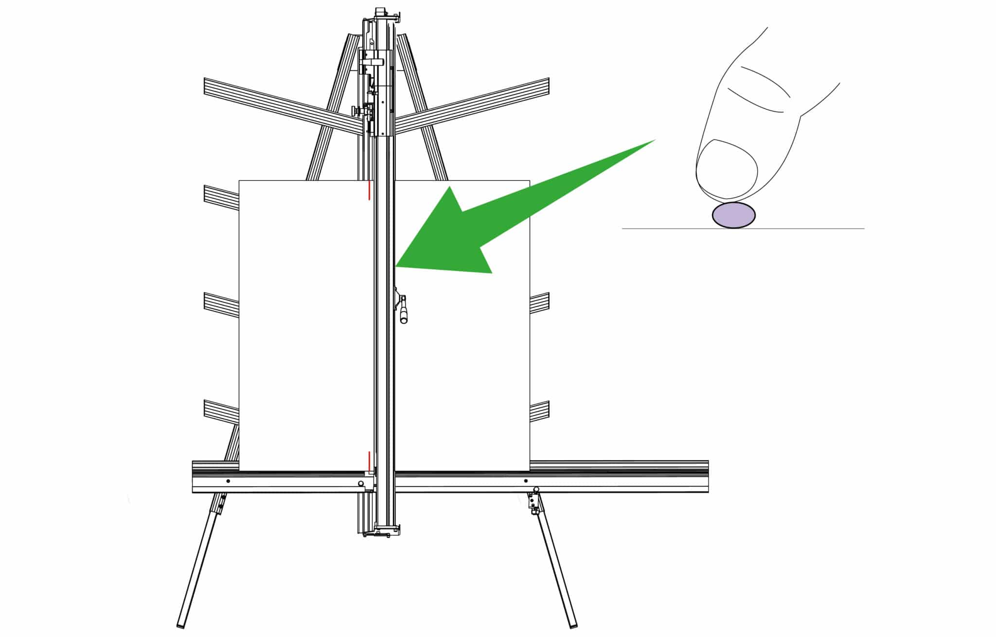
 |
Do this gently |
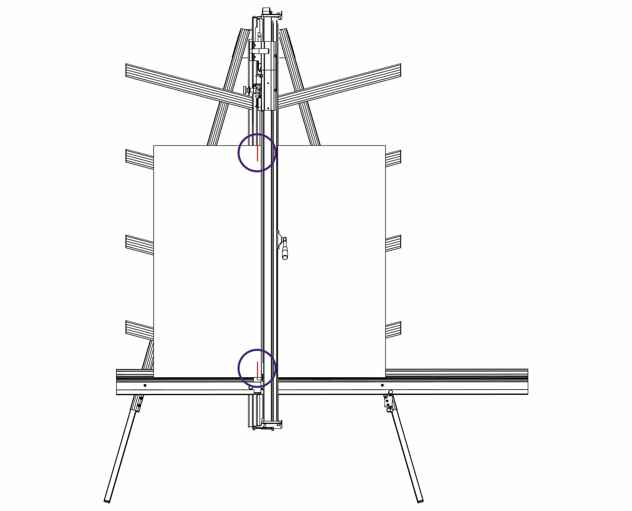
The Excalibur 3S is fitted with two sliding carriages running on a vertical slideway and each carriage is fitted with a cutting head. The top carriage is fitted with a twin wheel cutter for use with rigid boards such as aluminium composite panels, MDF, hardboards. Refer to Changing the twin wheel cutter > or Using the twin wheel cutter > for more details. The lower or multi-tool cutter head has a rotating turret arrangement where either of the two cutting tools can be selected (the cutting blade or the scoring blade).
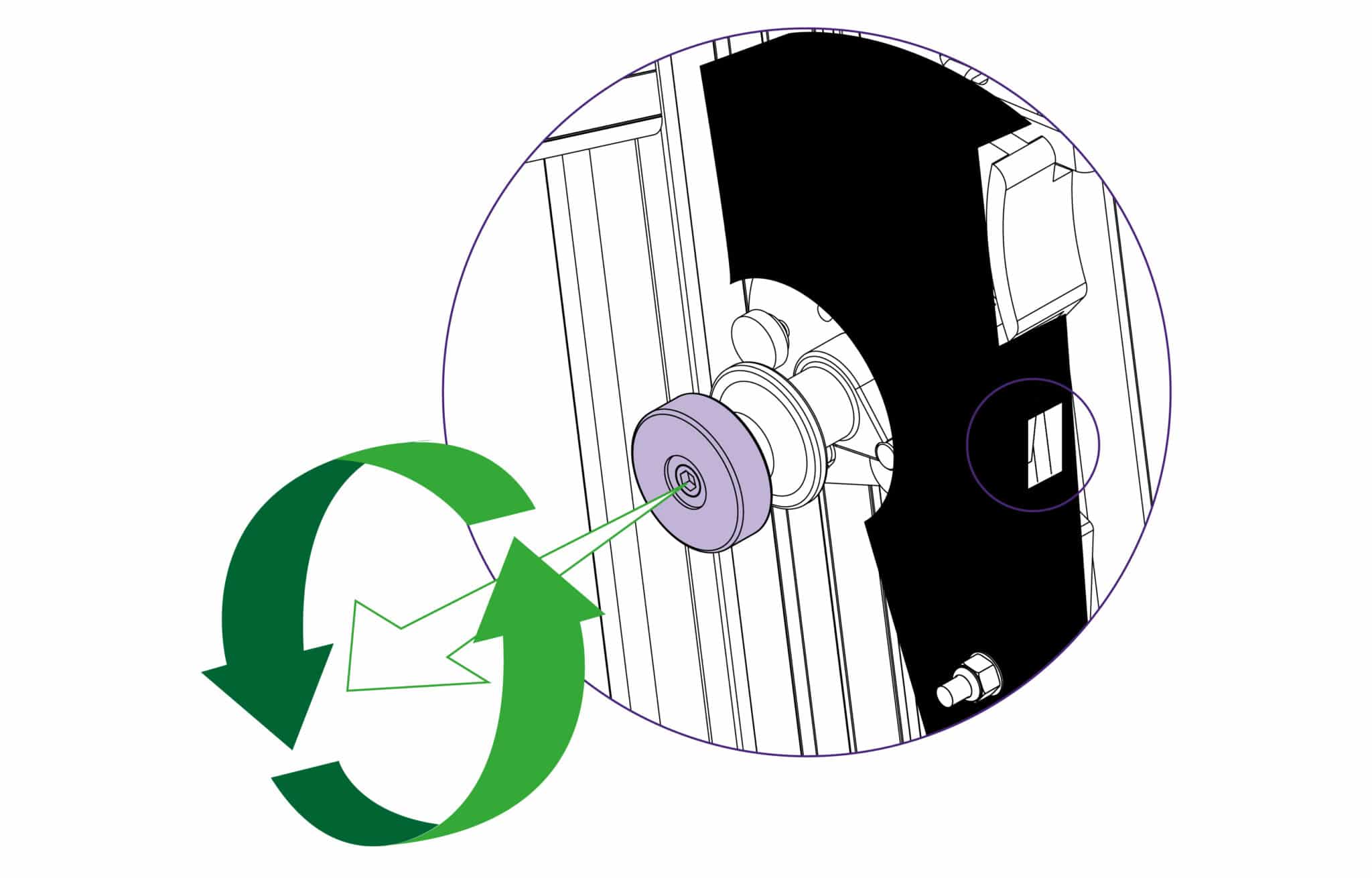
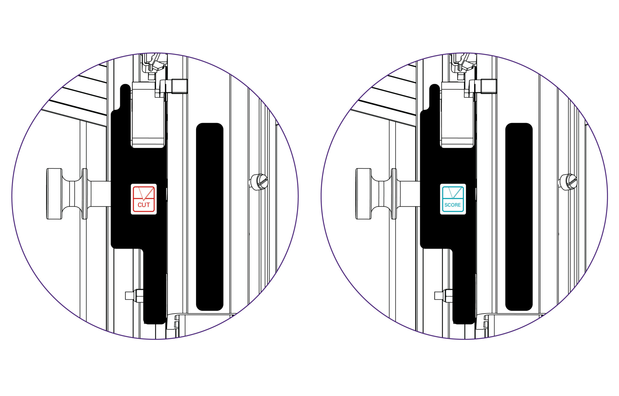
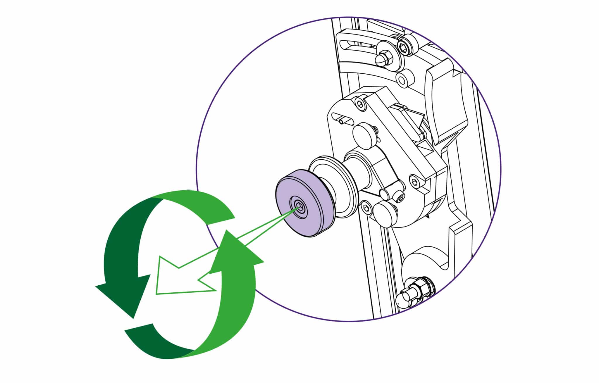
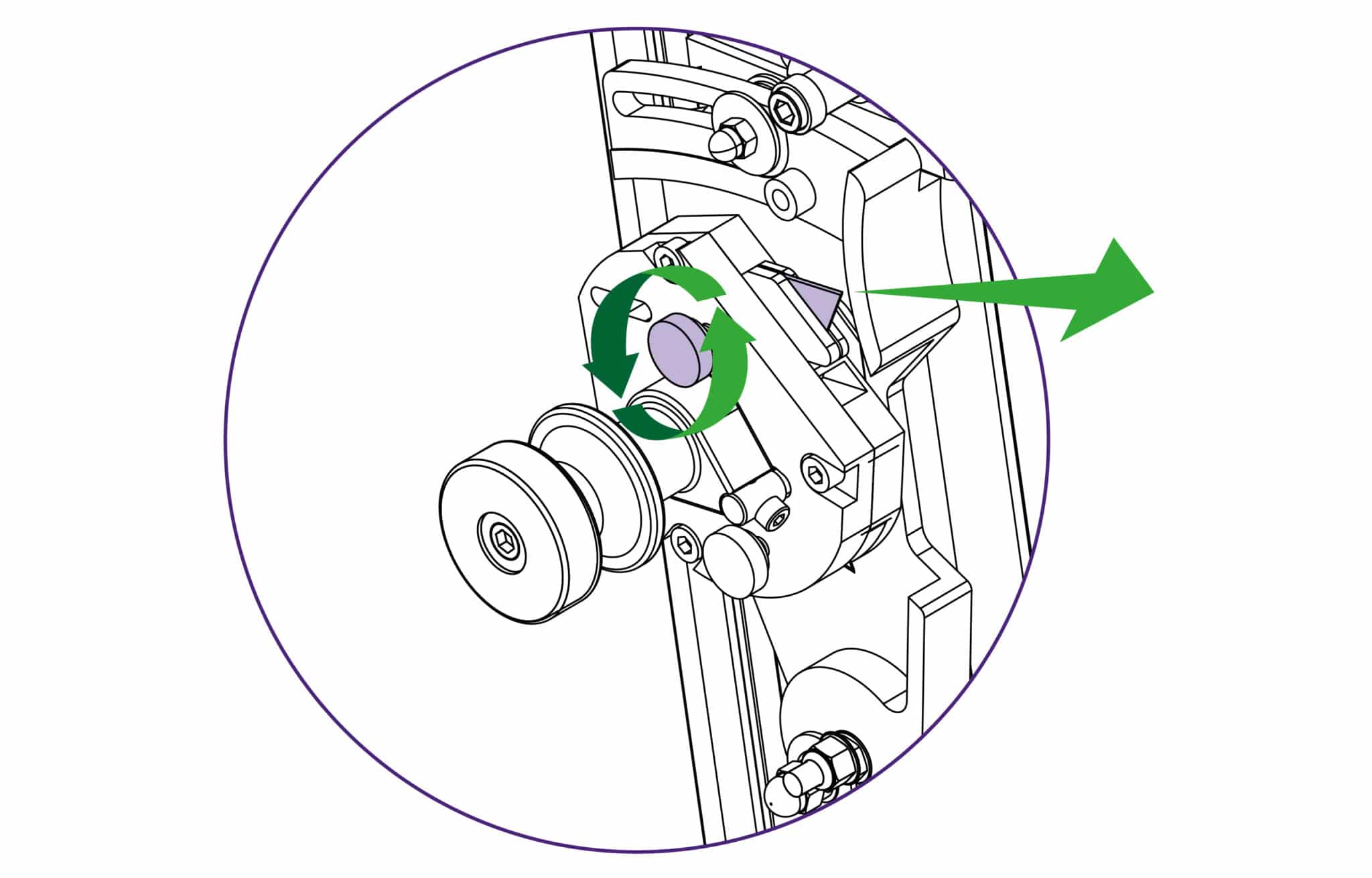
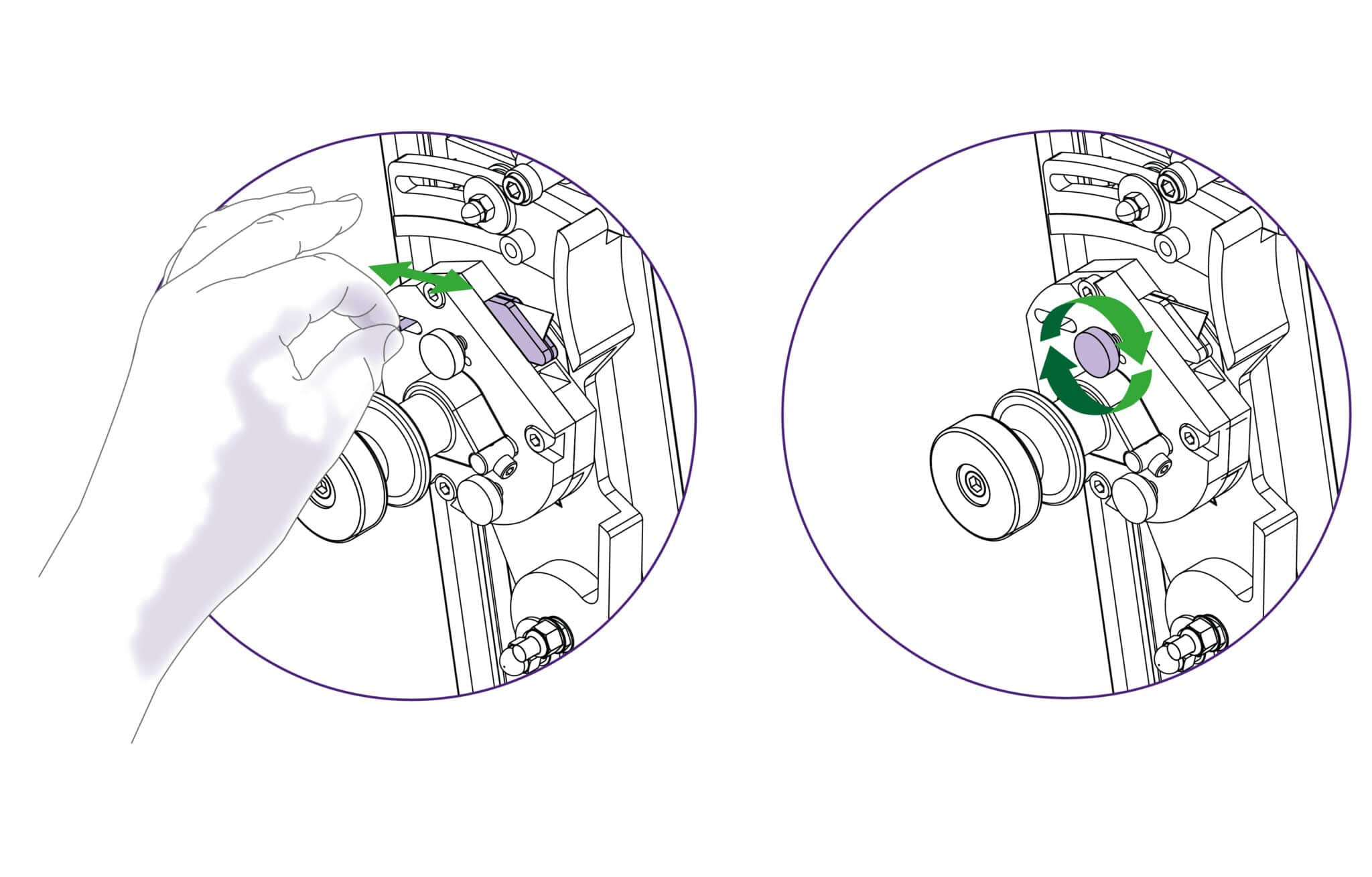
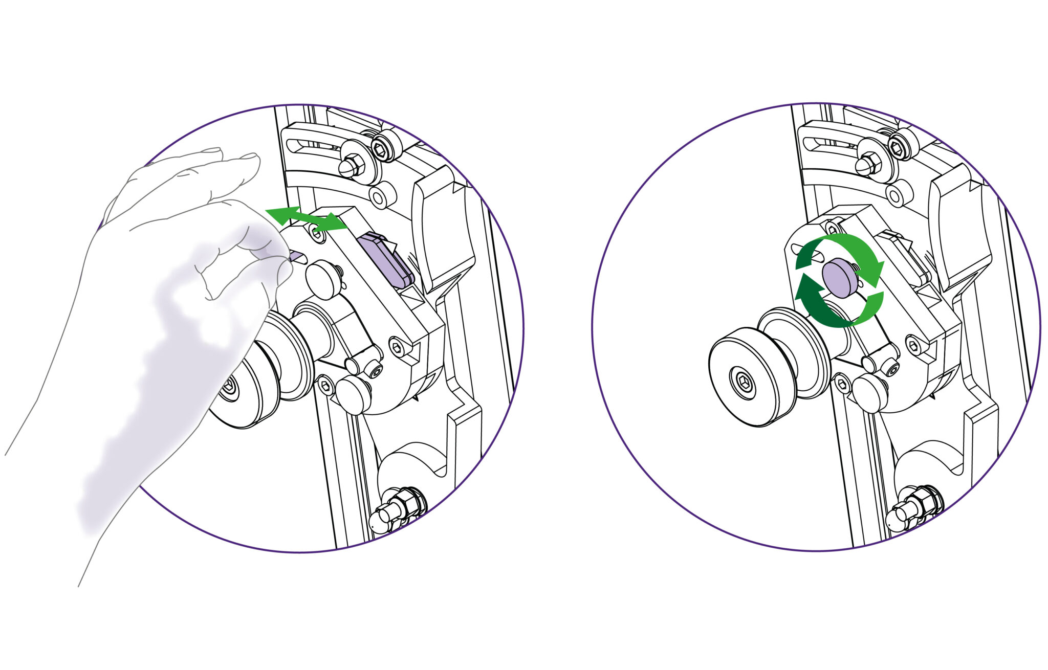
To select a different cutter pull the turret handle out to the left about 6mm (1/4”) and rotate in either direction, the turret will click into the correct position for the cutter indicated. Please note that there are three positions on the turret but only two positions are used on this version of the Excalibur.
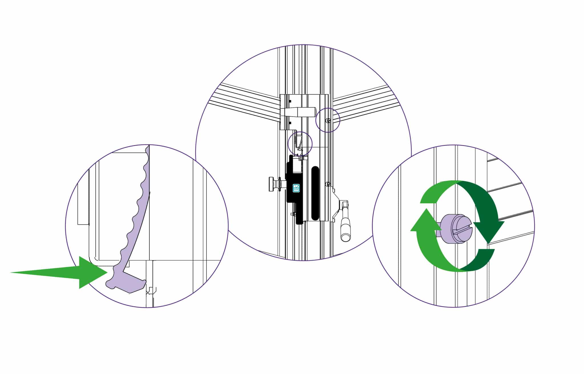
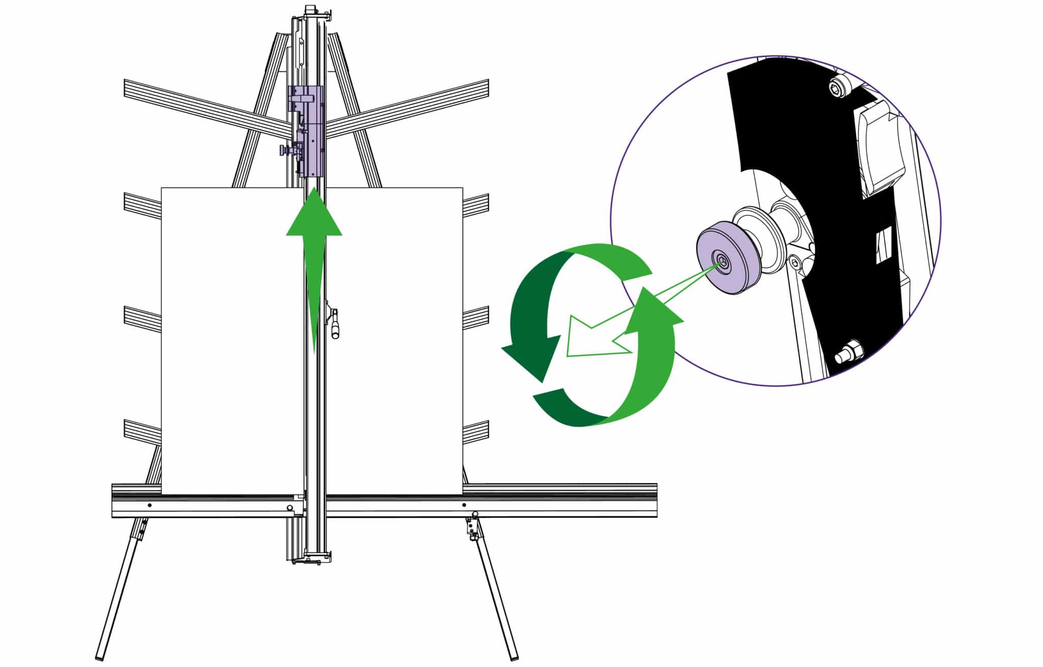
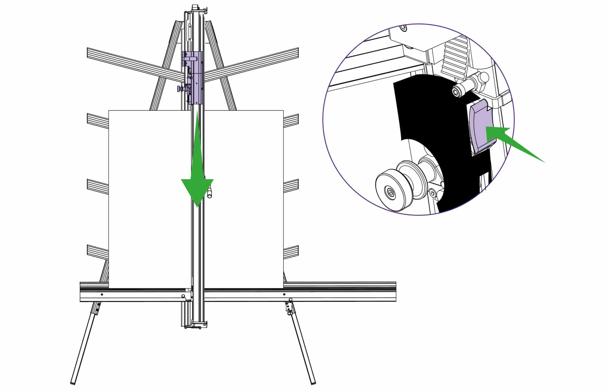
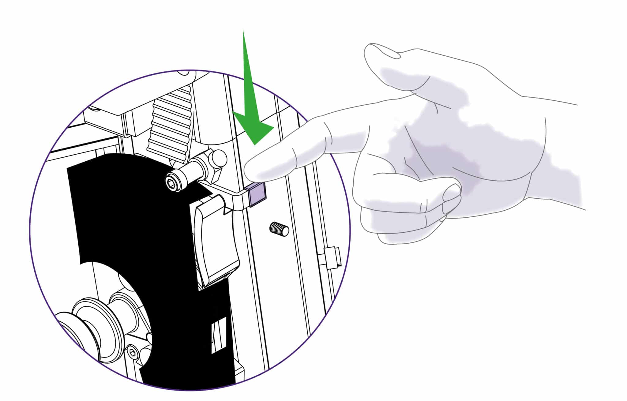
The counterbalance can be attached to either cutting head for easy, fatigue free working. it is normally attached to the twin wheel cutter but to attach it to the multi-cutter head, lock the twin wheel carriage in place using the white plastic thumb screw. Raise the multi-cutter to engage the counterbalance rocker, press the lower head of the rocker to connect it to the carriage.
For cutting most materials the support plates can be set about 12mm (1/2”) from the blade tip
Change or turn over the blade, insert it back into the turret as far as it will go. Tighten the blade clamping screw, the safety pin will engage to hold the blade in position. At this point the position of the blade support plates can be adjusted to suit the thickness of material being cut, further tightening of the screw will clamp the blade in position.
Rotate the turret back to the cutting position. Replace the guard ensuring it is locked closed.
Replacement medium utility blades are available from Keencut or your distributor.
Replacement wheels or cutters are available from Keencut or your distributor
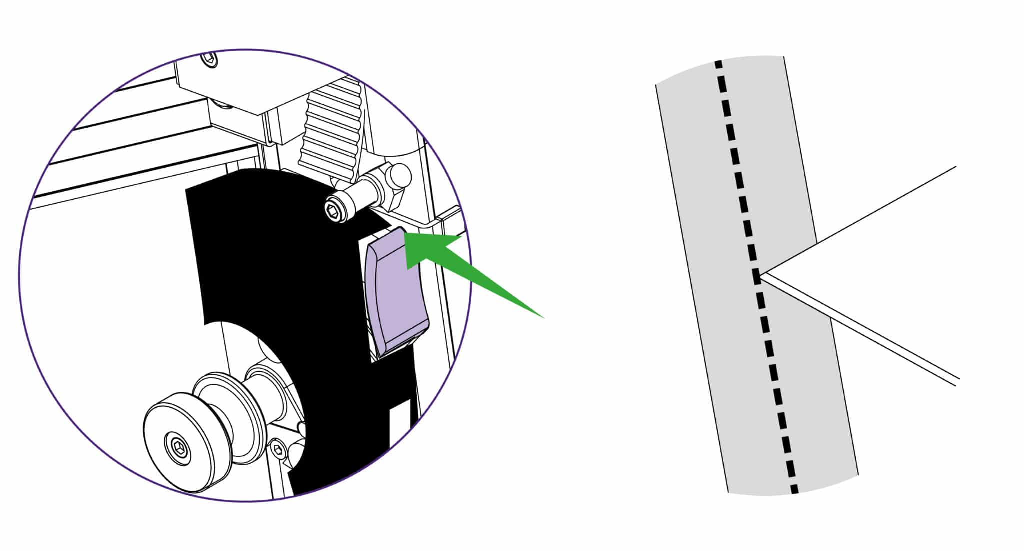
A unique feature of the Excalibur is the ‘ratchet latch’, this enables thick dense materials such as PVC foam board to be cut easily in stages. Count the number of ‘clicks’ to position the blade just below the surface of the material to make your first cut then add an extra ‘click’ for the second and subsequent cuts.
As a rough guide when cutting PVC foam board:
3MM (1/8”) Initial surface cut + 1 additional cut
5MM (1/4”) Initial surface cut + 1 or 2 additional cuts
10MM (3/8”) Initial surface cut + 3 or 4 additional cuts
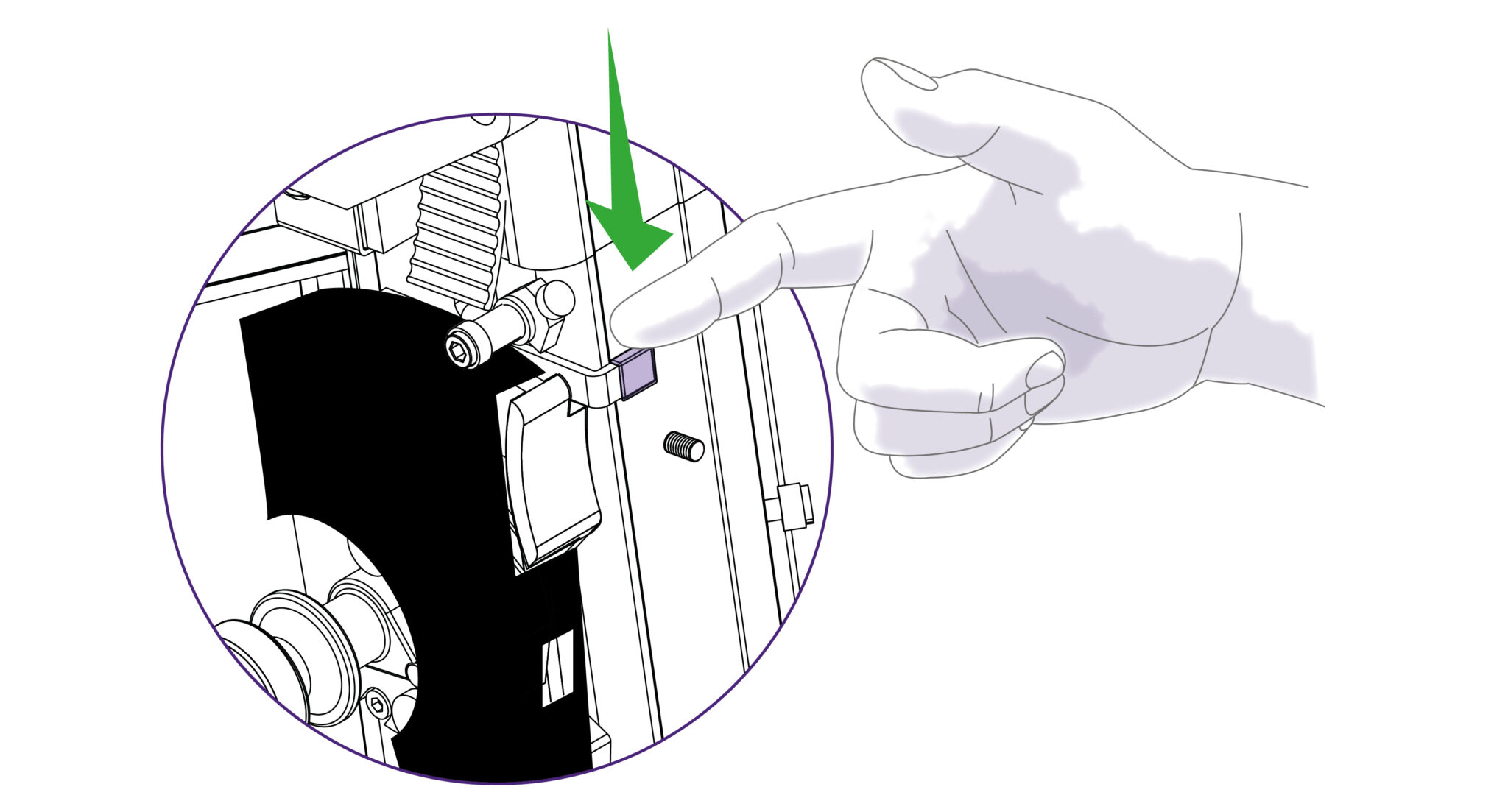
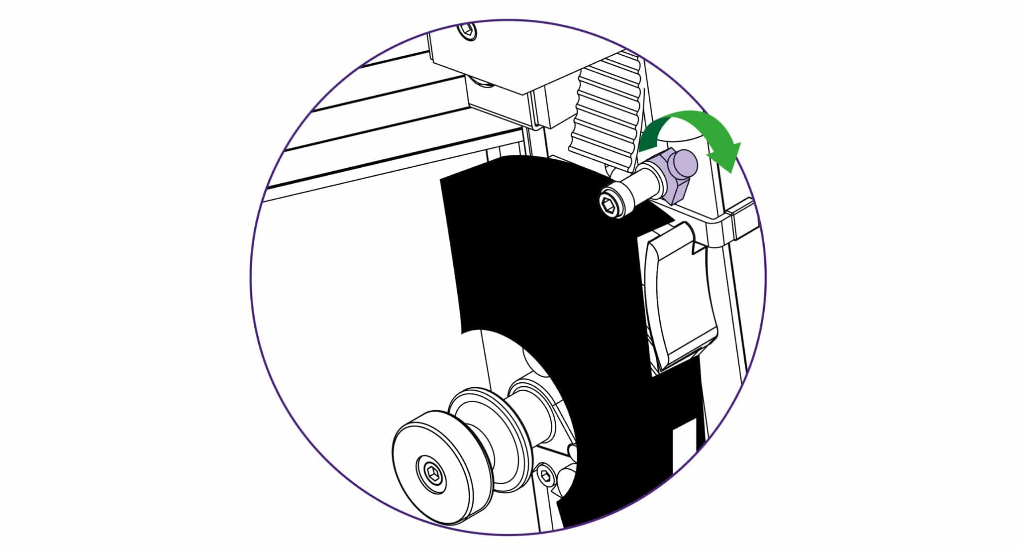
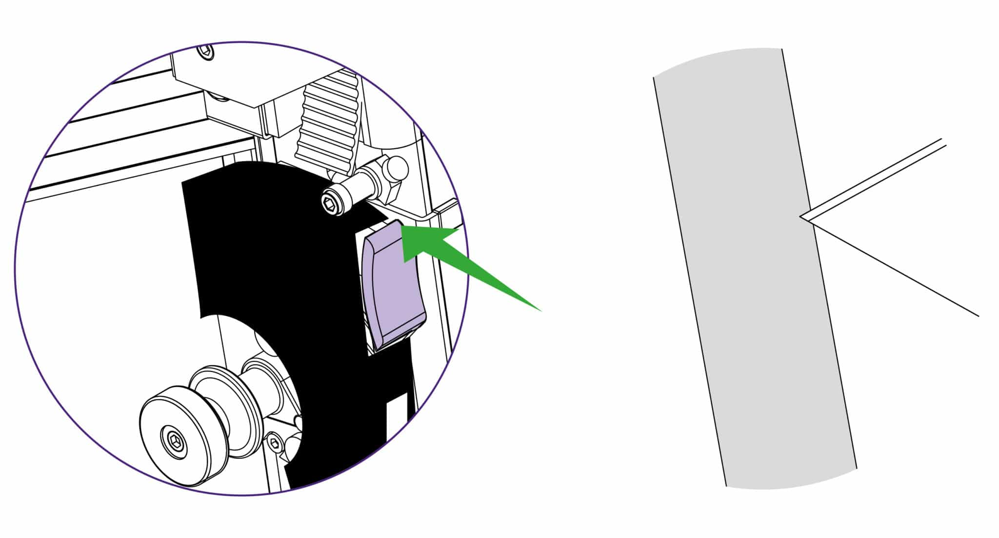
For some operations (such as scoring acrylic) the ratchet latch needs to be disengaged, so that finger pressure is used to make the score/cut. This is done by pulling the black knob on the edge of the spring spool down to face towards the user. To re-engage the ratchet latch push the small black knob away so it points upwards.
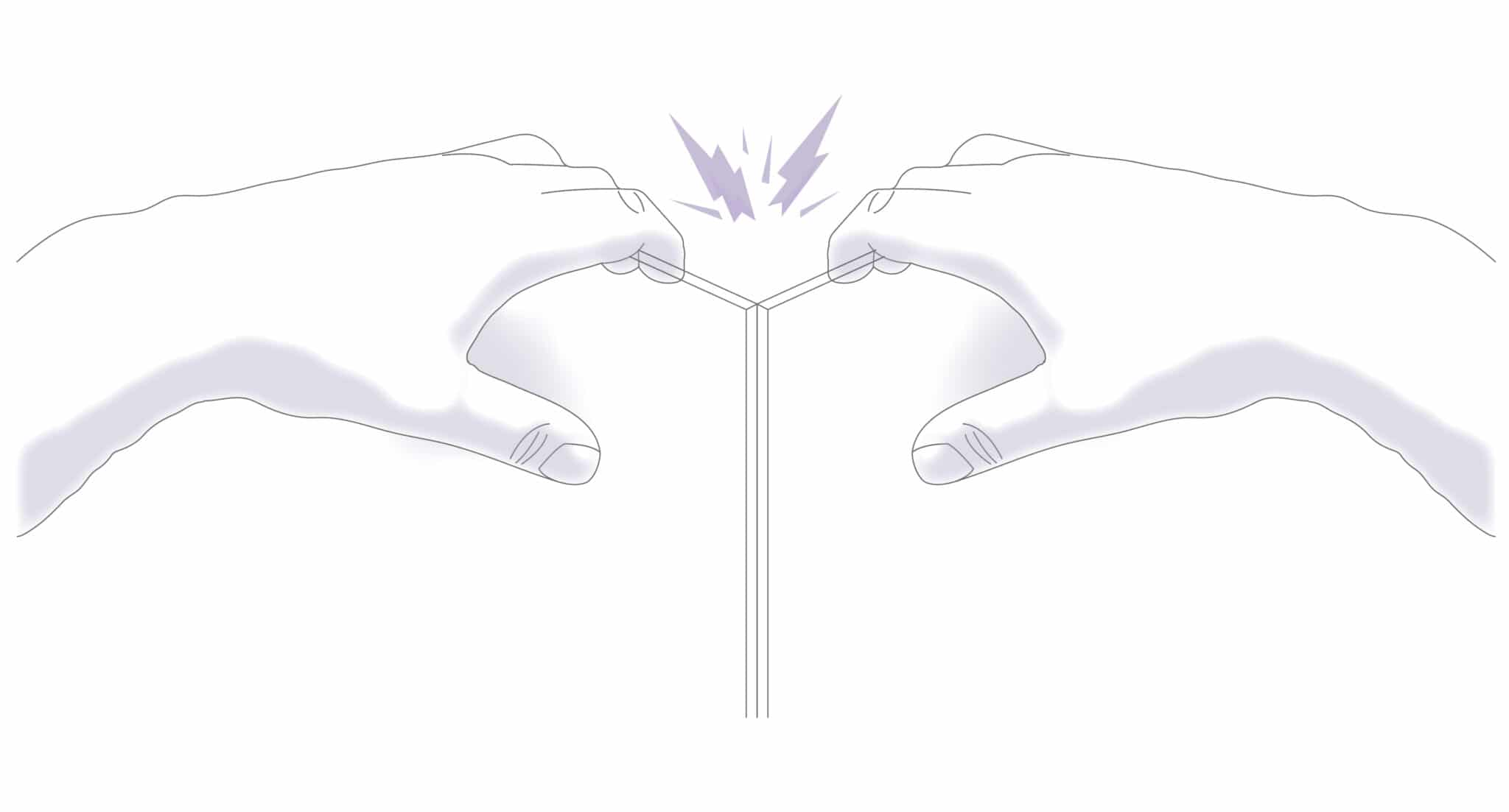
CAUTION ALWAYS USE HAND AND EYE PROTECTION WHEN SNAPPING PLASTIC
NOTE : The scoring blade is designed to score acrylics, Plexiglas and other similar rigid plastics. Trials should be carried out on scrap materials first to ensure you obtain the required standard of cut.
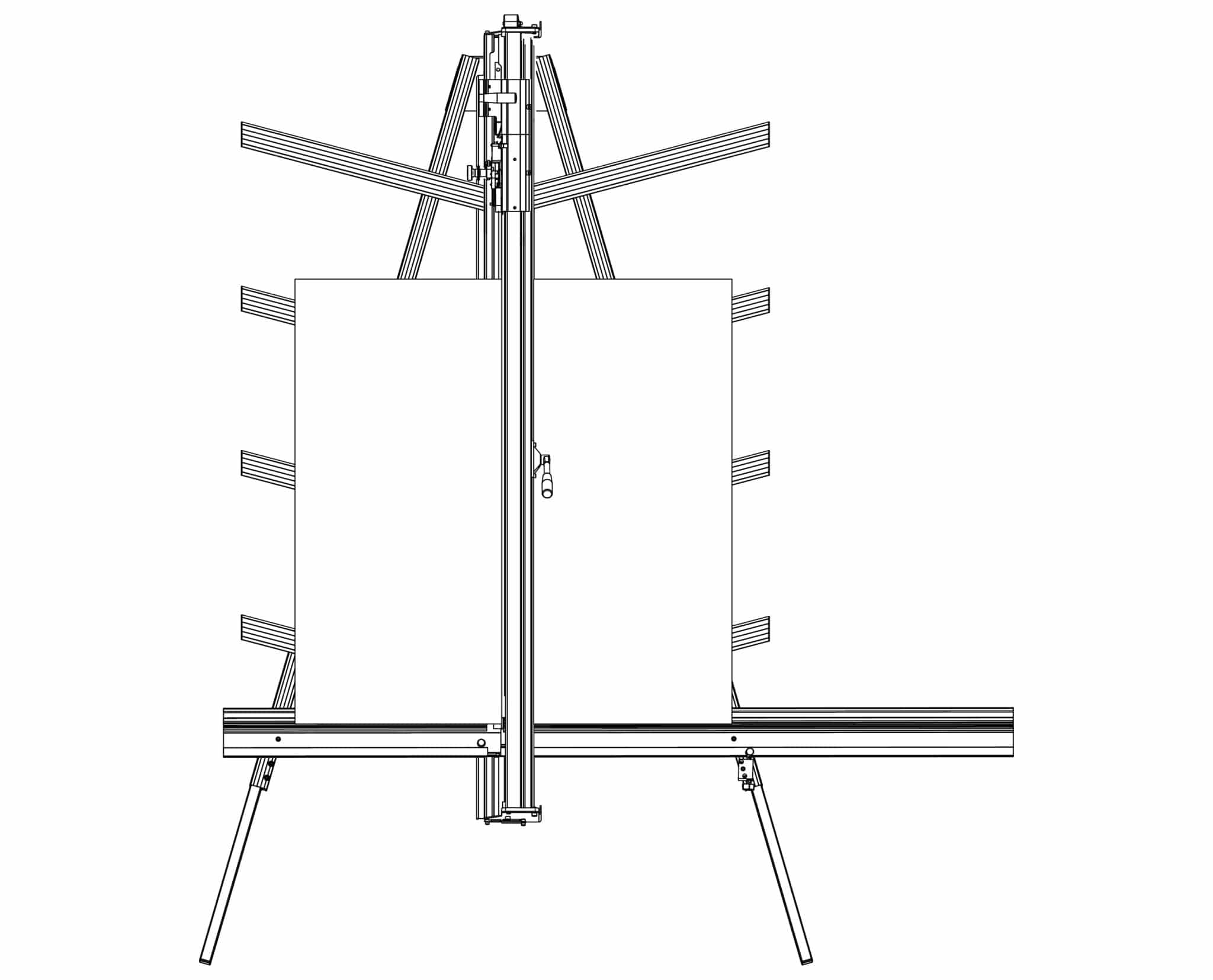
The twin wheel cutter must be parked above the top level of the clamp when not in use otherwise the cutter will interfere with the sightline strip if the clamp is operated.
The twin wheel cutter is mounted on the upper cutting head and is used for cutting rigid materials such as aluminium composite panel and MDF up to 3mm (1/8”). Many other softer boards and card can also be cut, trials should be carried out to ensure the desired quality of cut is obtained.
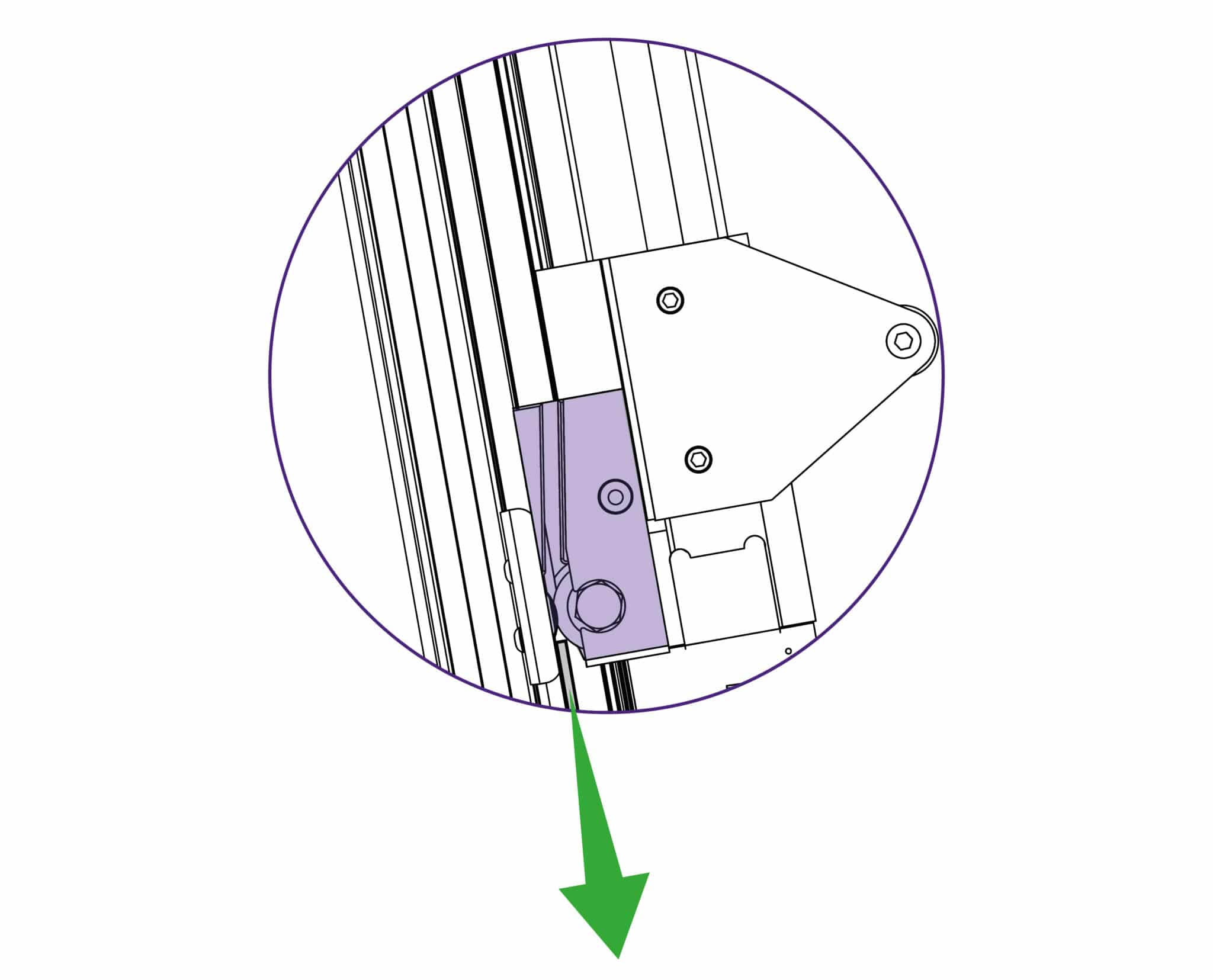
The cutting wheels generally last more than a year with average use but this is dependant upon daily use and the material being cut.
The signs the wheels are wearing out are:
1) A rough finish predominantly on the right hand side of the cut, with flaking on material such as MDF.
2) The bottom of the cut bursting out rather than being cut neatly.
3) The board trying to turn under the clamp when being cut (also check the clamp pressure).
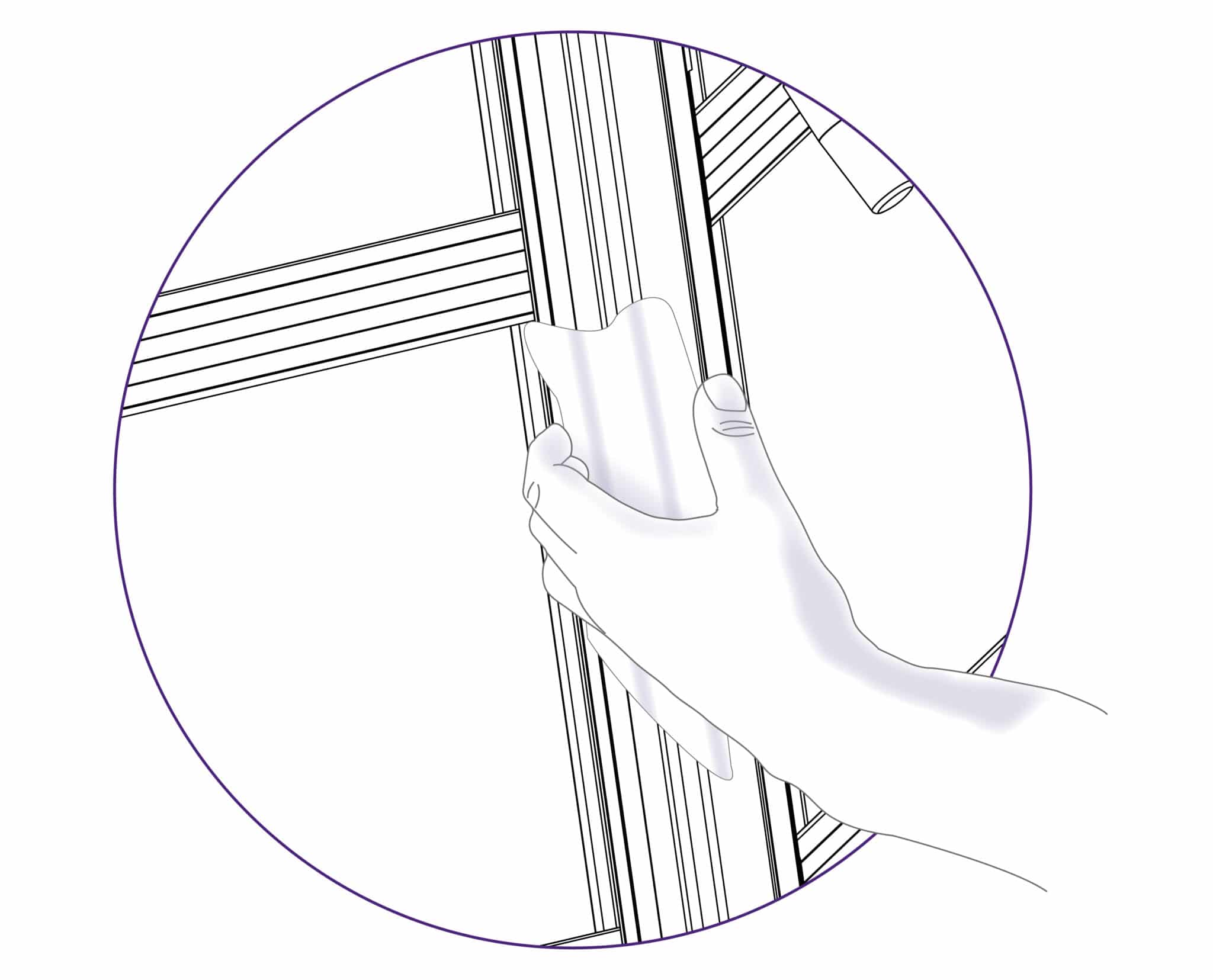
Keencut machines are designed to be virtually maintenance free, however we do recommend regular cleaning
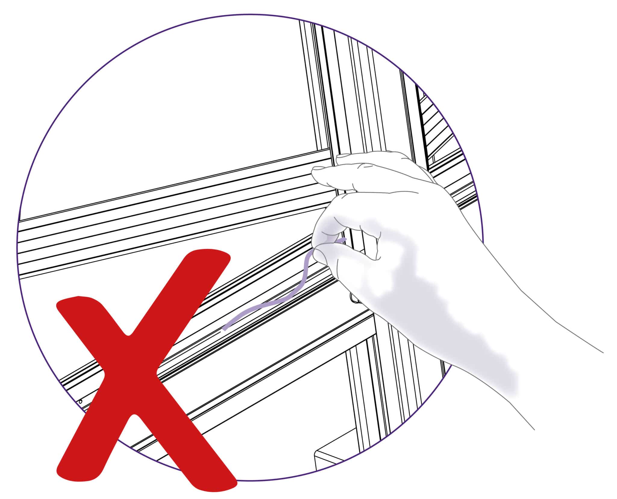
DO NOT USE OIL ON ANY PART OF THE MACHINE
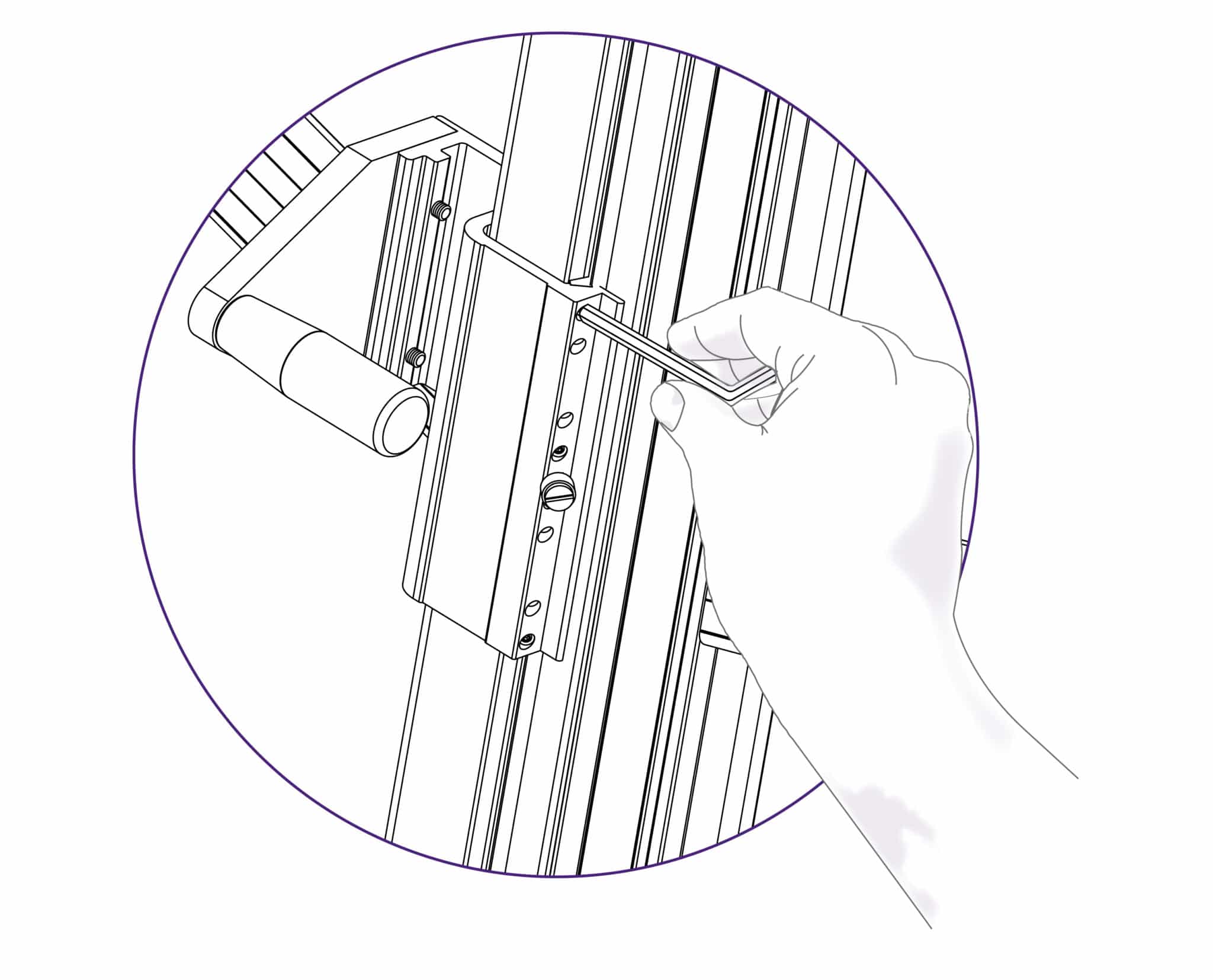
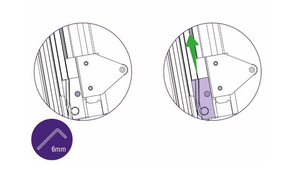
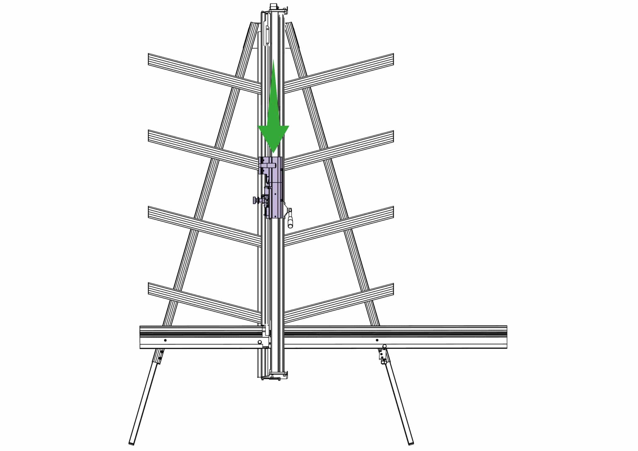
Attach the balance weight (see The multi-tool cutter and the counterbalance >) to the other cutting head, hold the cutter at waist height and place a 2mm hexagon wrench on the top adjustment screw.
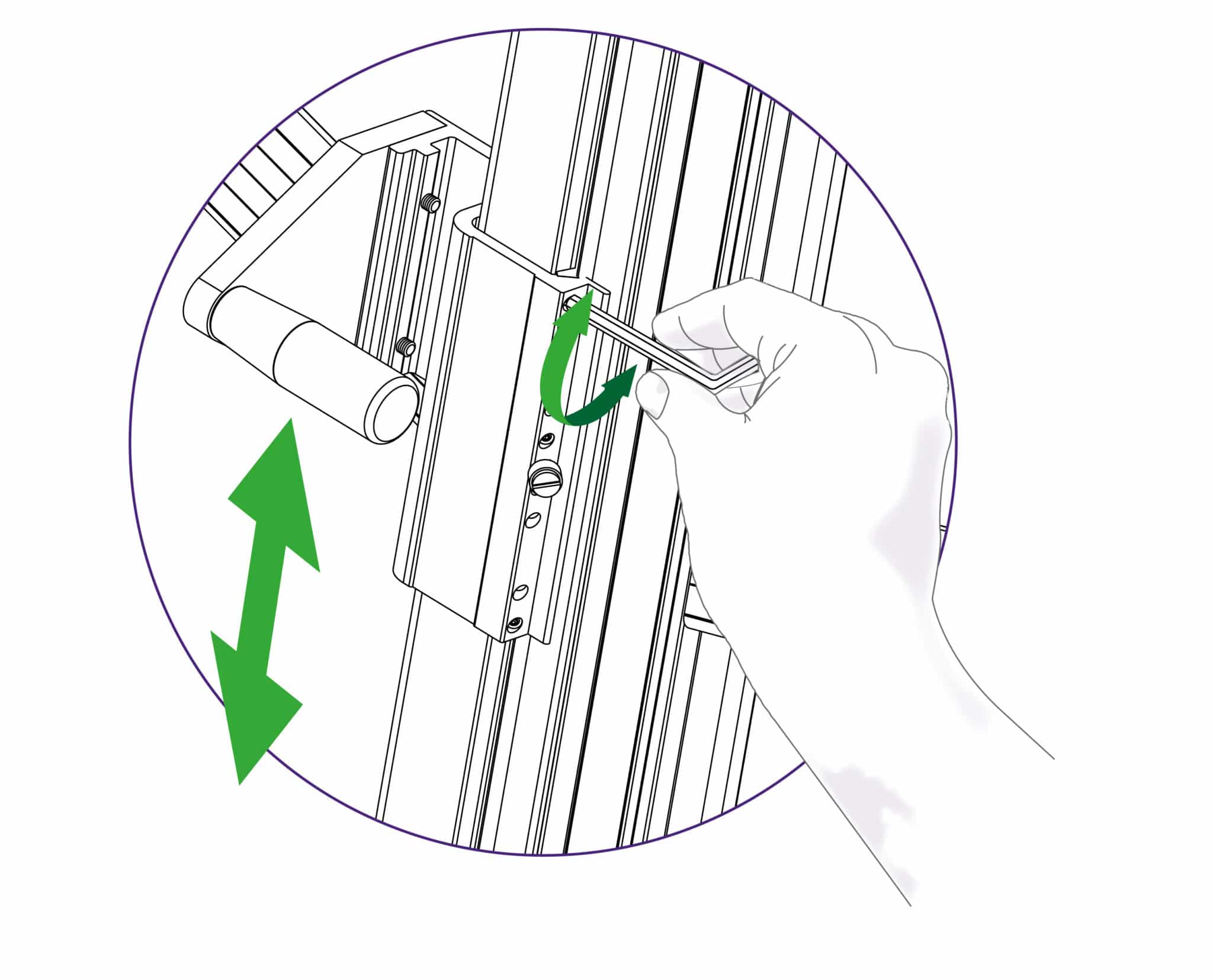
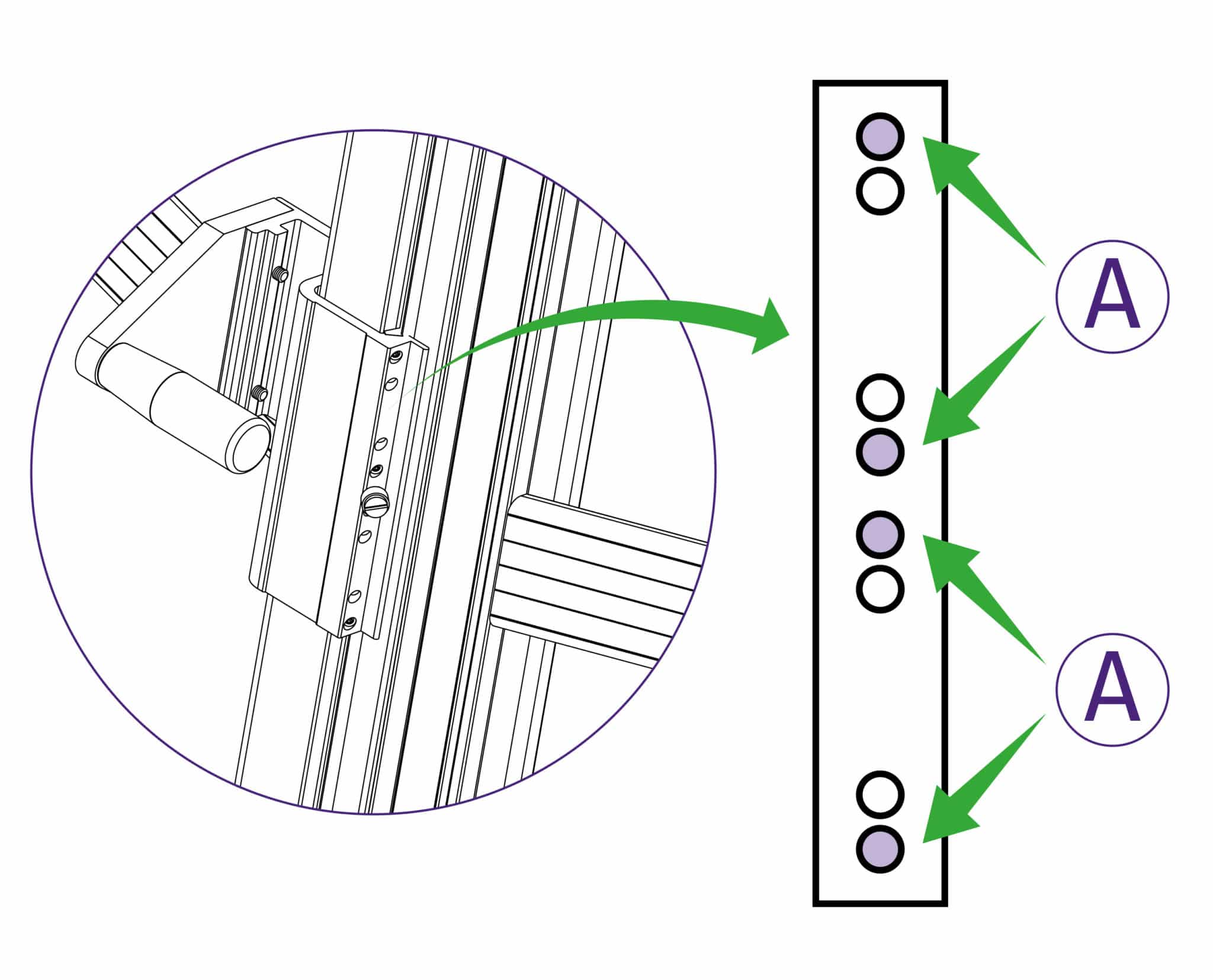
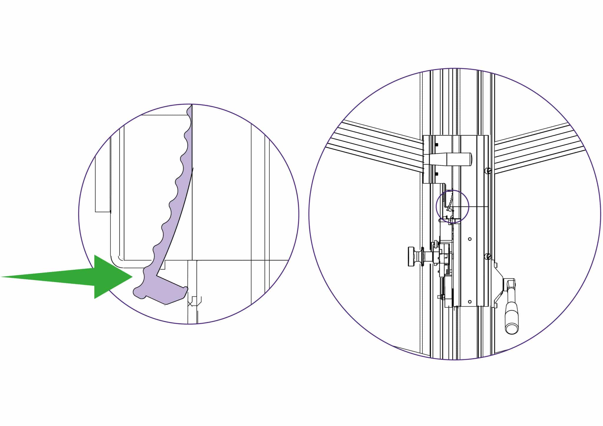

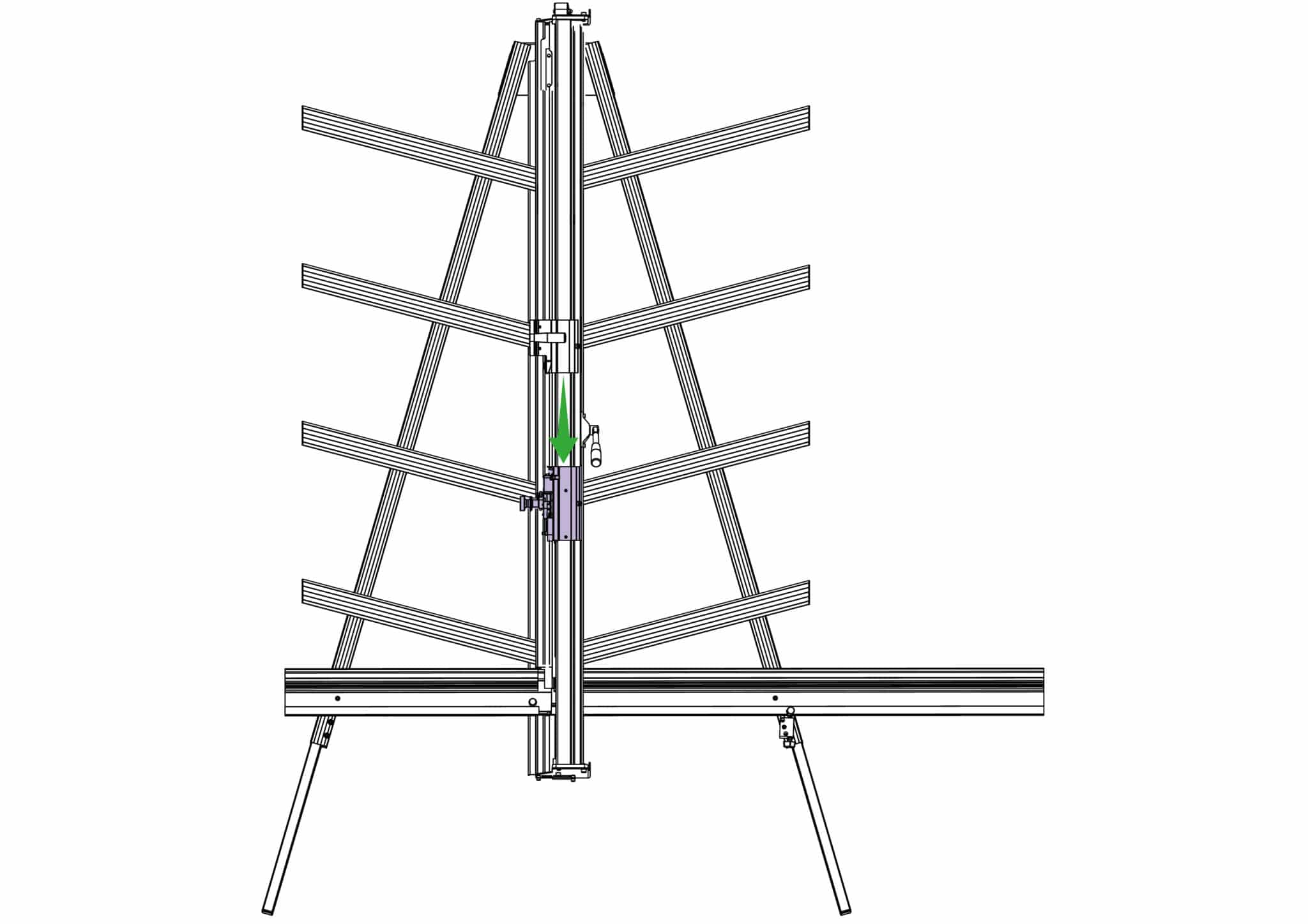
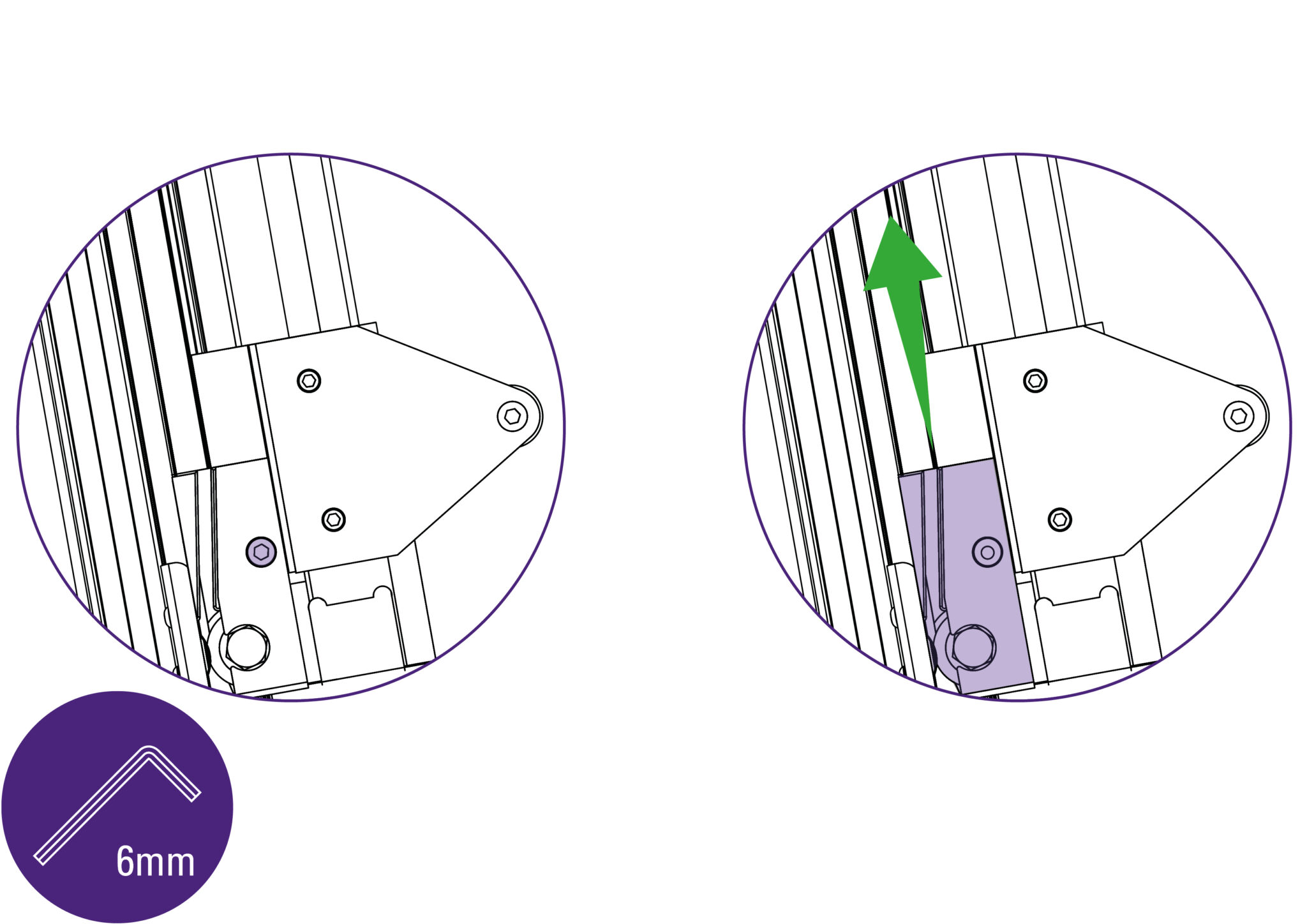
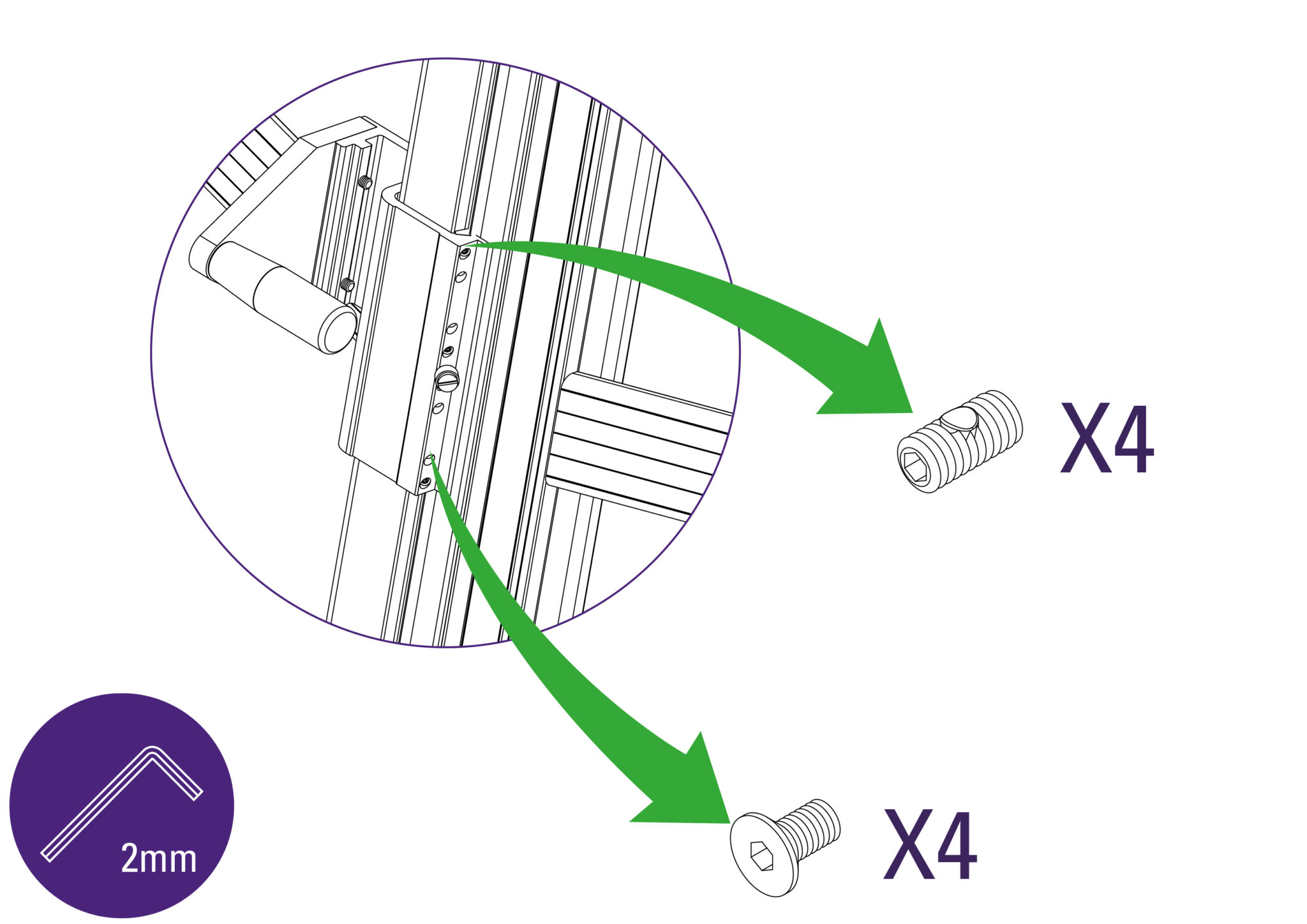
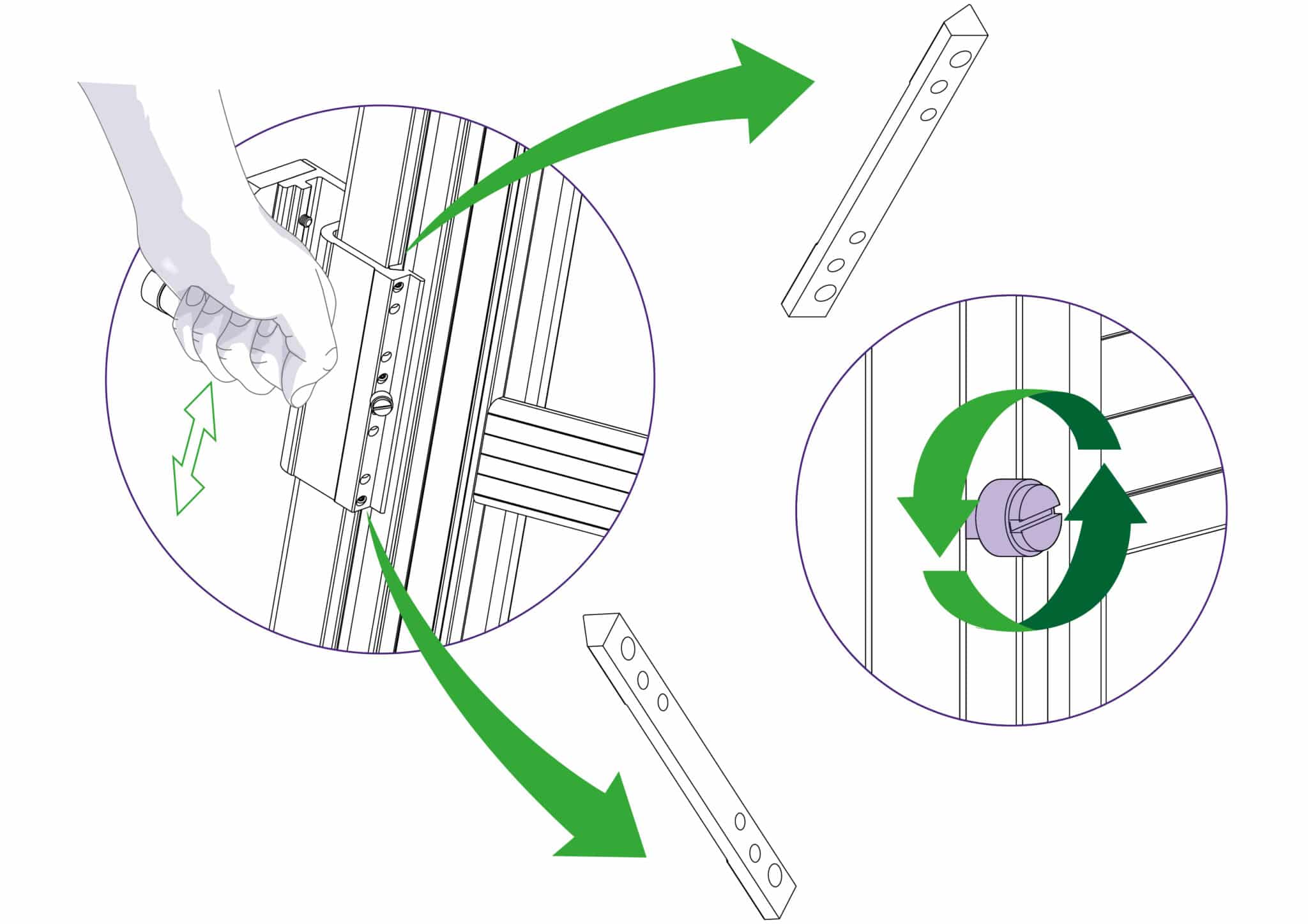
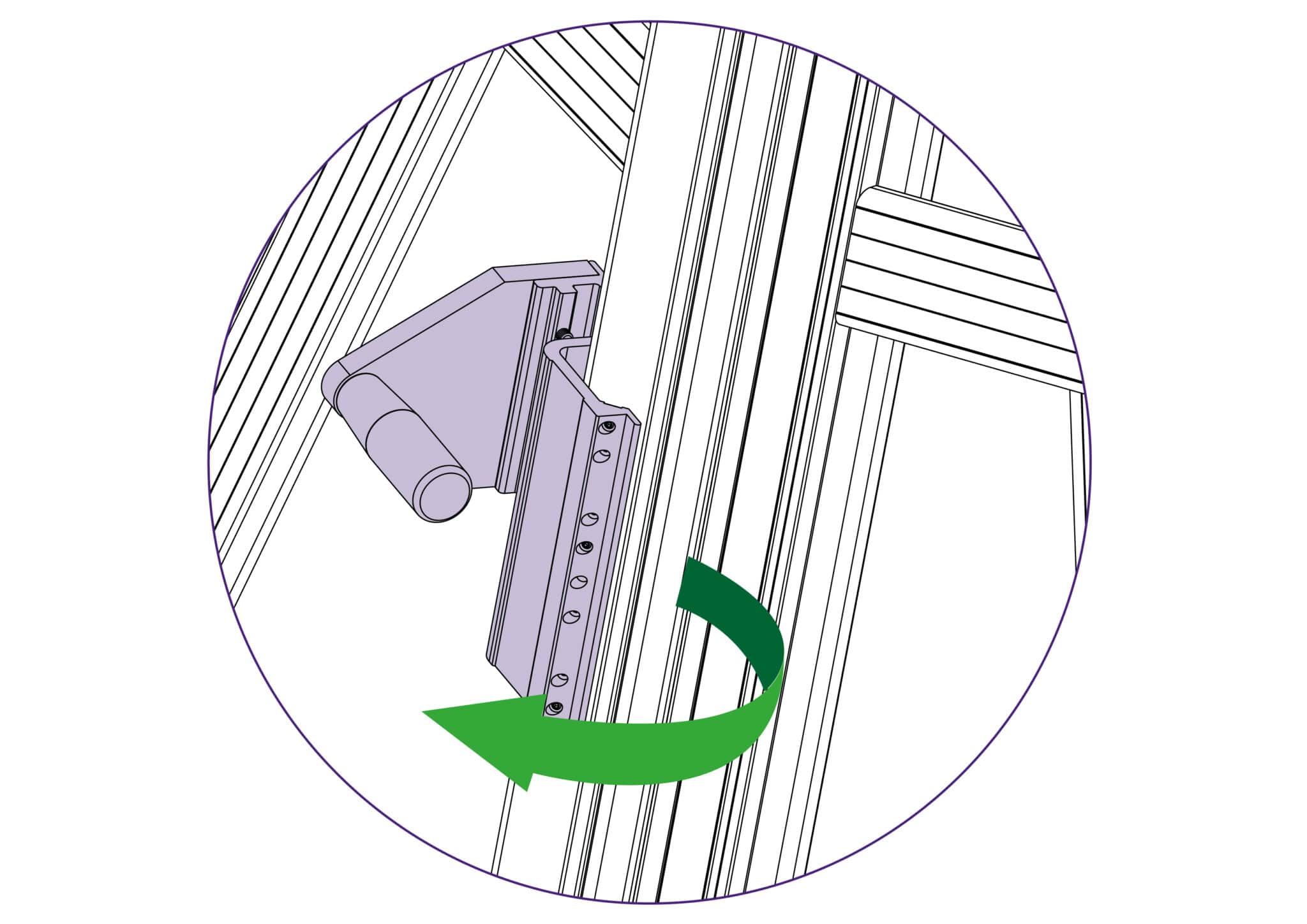
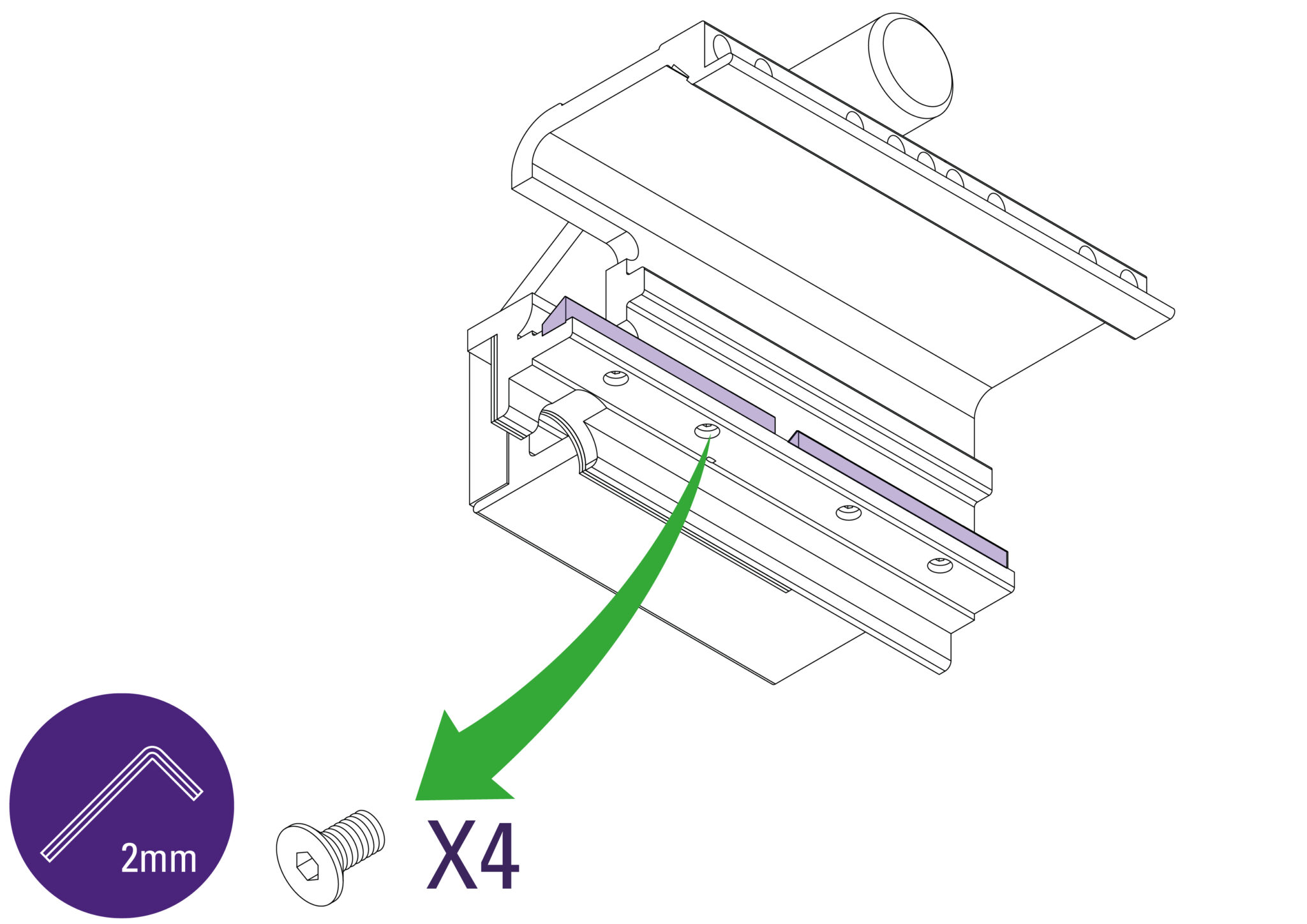
Use a 2mm Allen (Hex) key to remove the screws holding the internal bearings in place.
Reverse these steps to re-install. Refer to Adjusting the sliding bearings> to adjust the sliding fit.
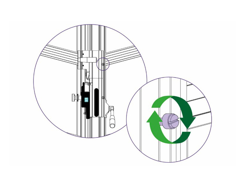
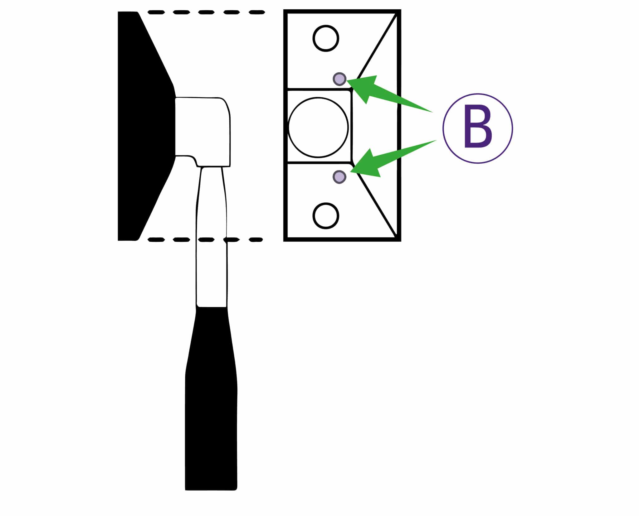
The pressure of the clamp is in relation to the amount of pressure applied to the operating handle. However in time the maximum clamping pressure can reduce due to wear on the friction black (hidden within the machine), compensation for this can be made by adjusting the two small grub screws in the operating handle housing as shown. Turning the screws clockwise will increase the maximum clamping pressure.
NOTE: The sightline strip is fitted to your machine but may wear or get marked with use. A spare strip is included with the machine, replacement strips are available from your distributor or Keencut.
The sightline strip is fixed to the clamp and then trimmed using the cutting blade to give an accurate guide when cutting to trim lines, the edge of an image or pencil marks.
NOTE: Do not engage the twin wheel cutter until after reading its instructions for use in Using & changing the twin wheel cutter>. Engaging the twin wheel cutter interferes with the sightline strip and can cause damage to it. A gap is left in the sightline strip at a convenient height to enable the twin wheel cutter to be engaged.
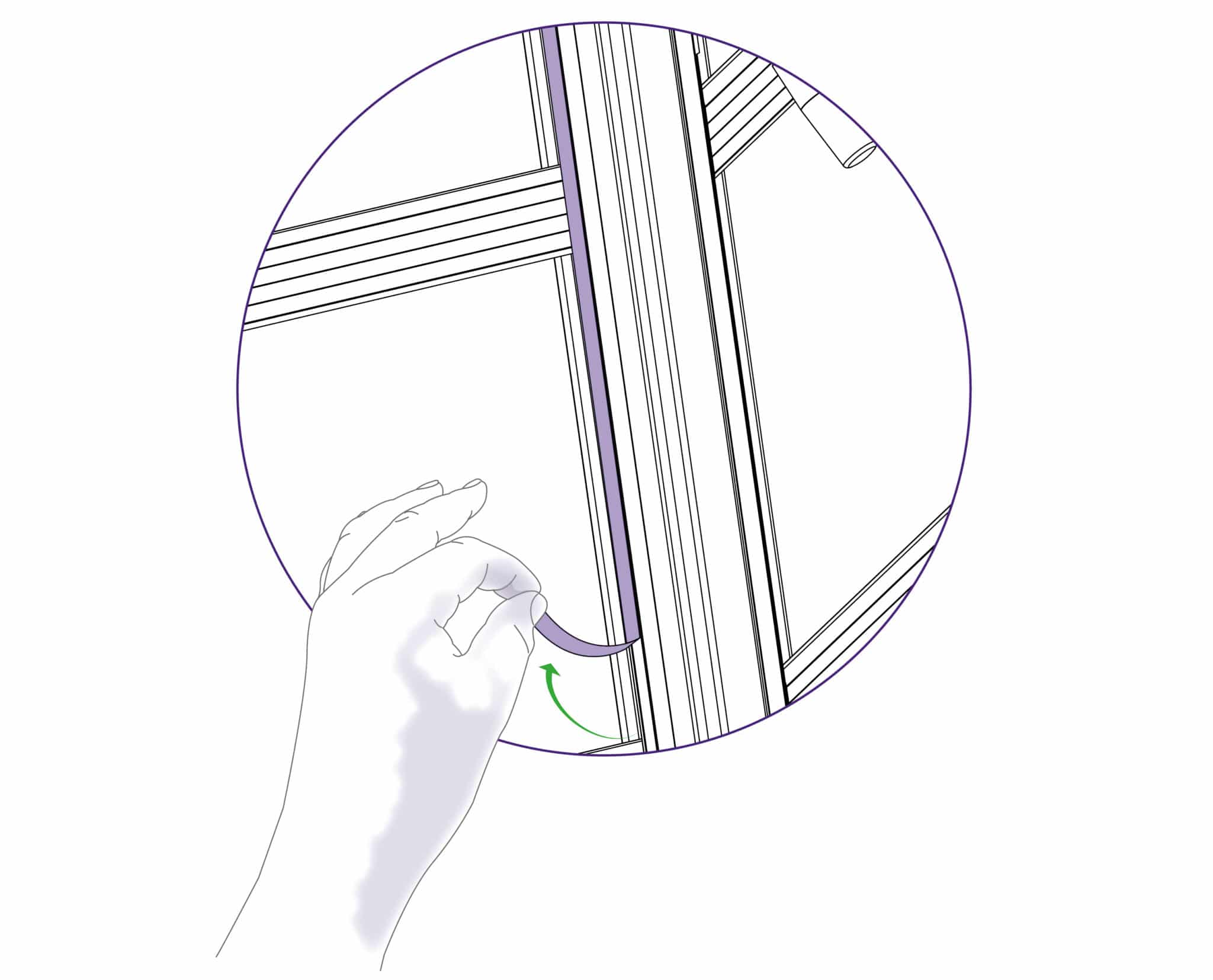
Remove the worn sightline strip by peeling it off and clean any surplus adhesive with solvent cleaner on a cloth. Remove the backing paper and starting at the bottom press the strip firmly in the channel provided working upwards and cut off at a convenient height. Leave a gap of 18cm (7”) and then fit the remainder of the strip.
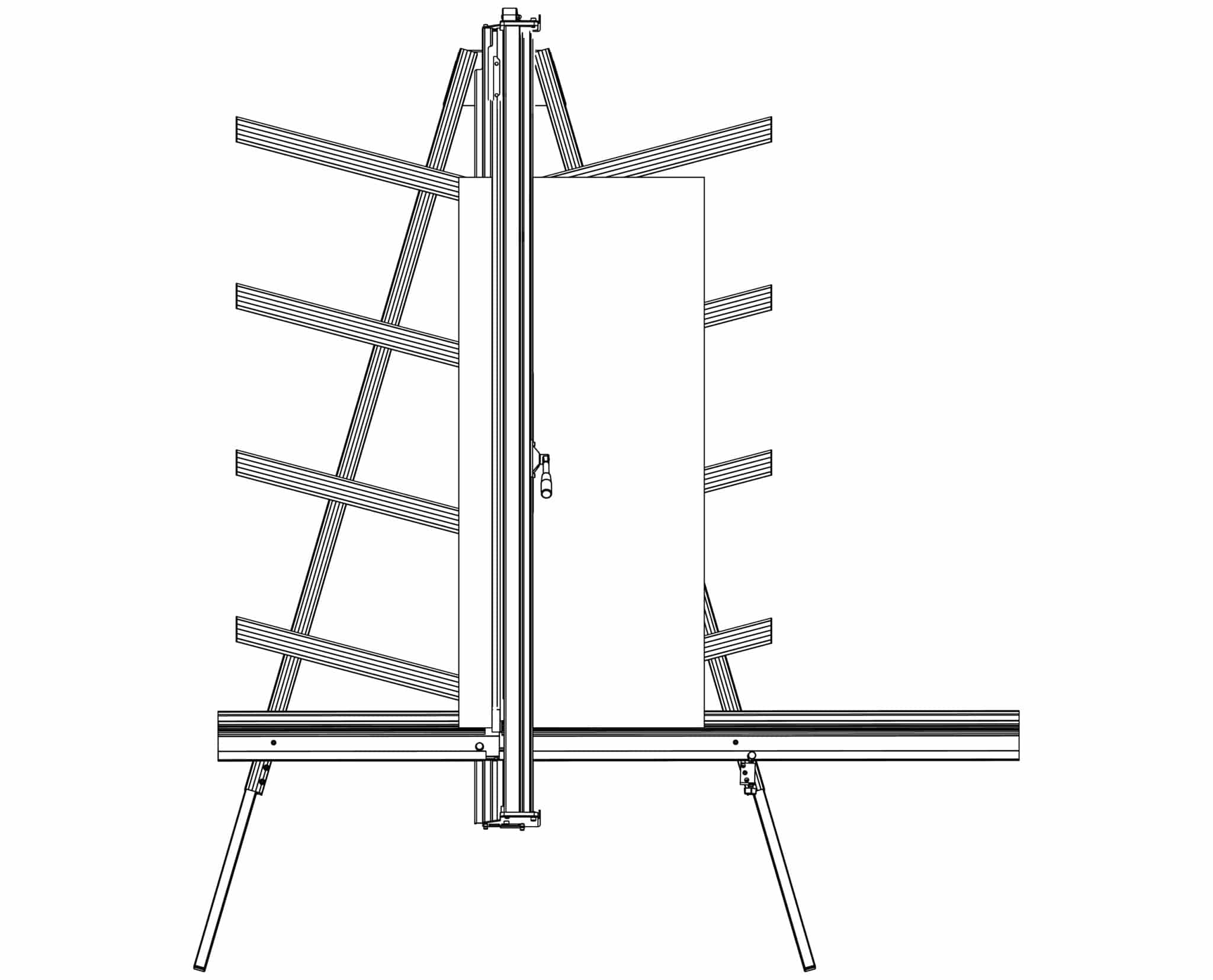
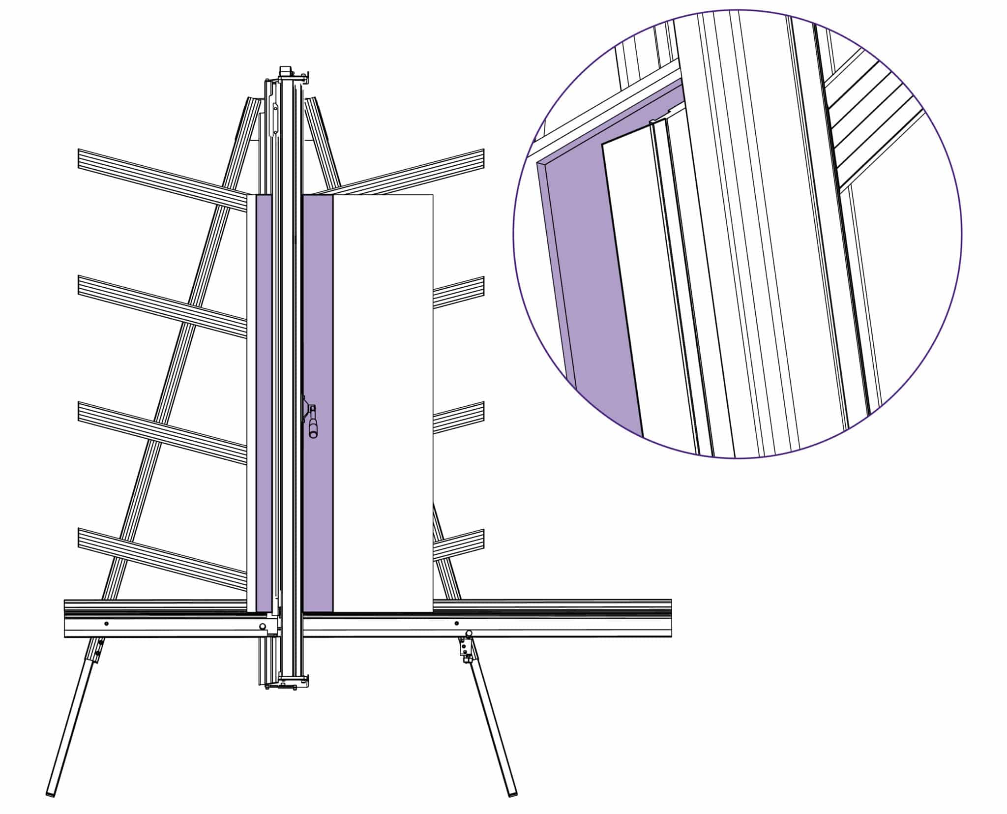
Keep fingers clear and using a block or tool hold down the top left corner of the strip to start the cut. With the turret ratchet disengaged (see Using the scoring blade >) press the blade lightly on to the surface of the sightline strip and score along the full length. Repeat and trim the sightline strip in 2 or 3 cuts.
NOTE: If a board is not available to go the full length of the clamp use two or more pieces or trim the strip in stages.
This User Guide for the Excalibur 3S gives advice on cutting techniques, care and maintenance of your machine.
Before using your machine make sure that you have installed and calibrated it correctly. Full details are in the Installation Manual.

Ⓒ Keencut 2026 | Baird Rd, Corby NN17 5ZA UK | Contattaci |
Creato da DeType | Privacy | Clausola di esonero sito web
Politica dei resi |
Seguici


