

Excalibur 3S user guide – Maintenance
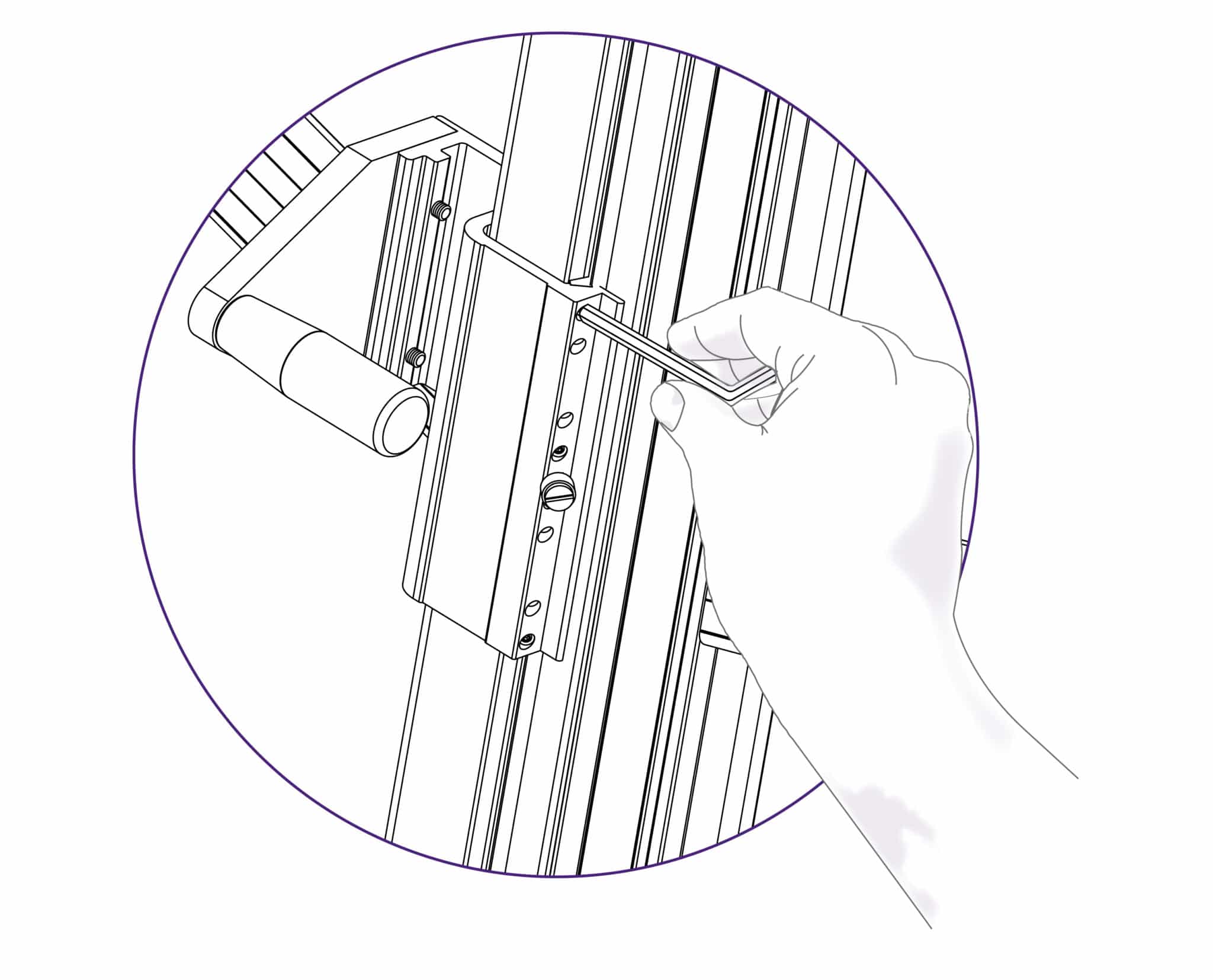
Attach the balance weight (see The multi-tool cutter and the counterbalance >) to the other cutting head, hold the cutter at waist height and place a 2mm hexagon wrench on the top adjustment screw.
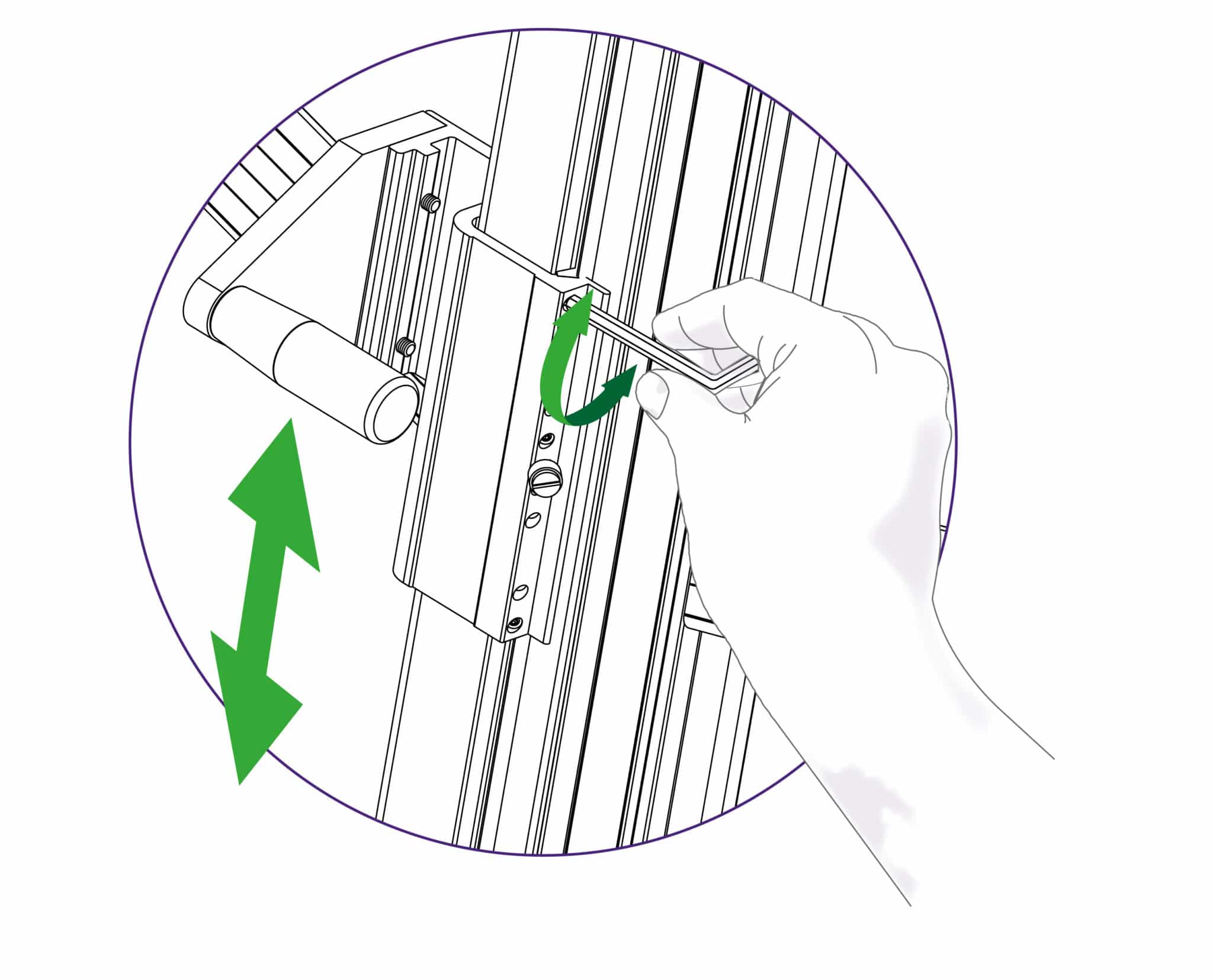
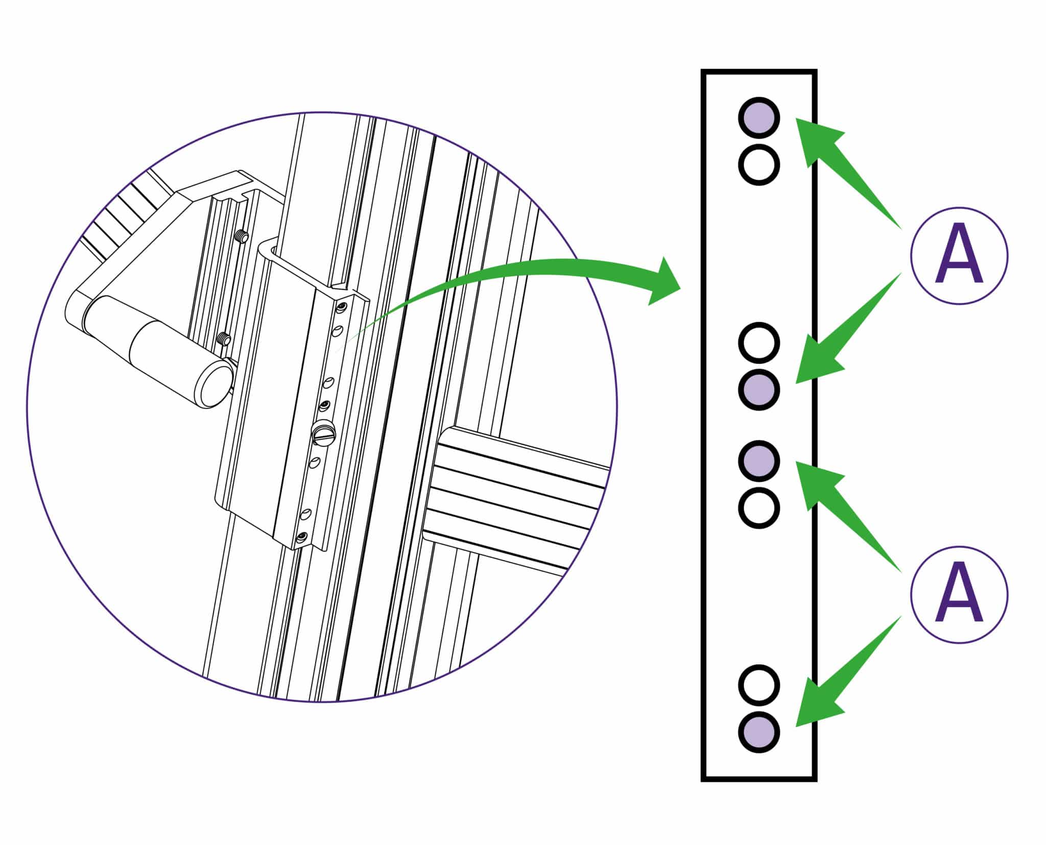

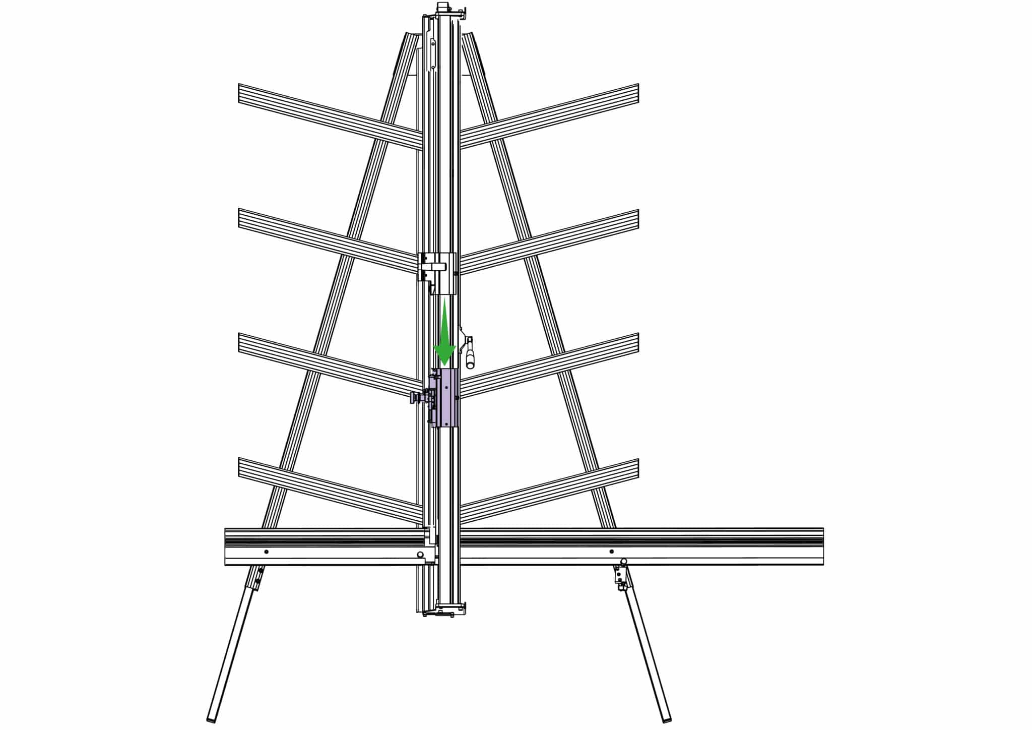
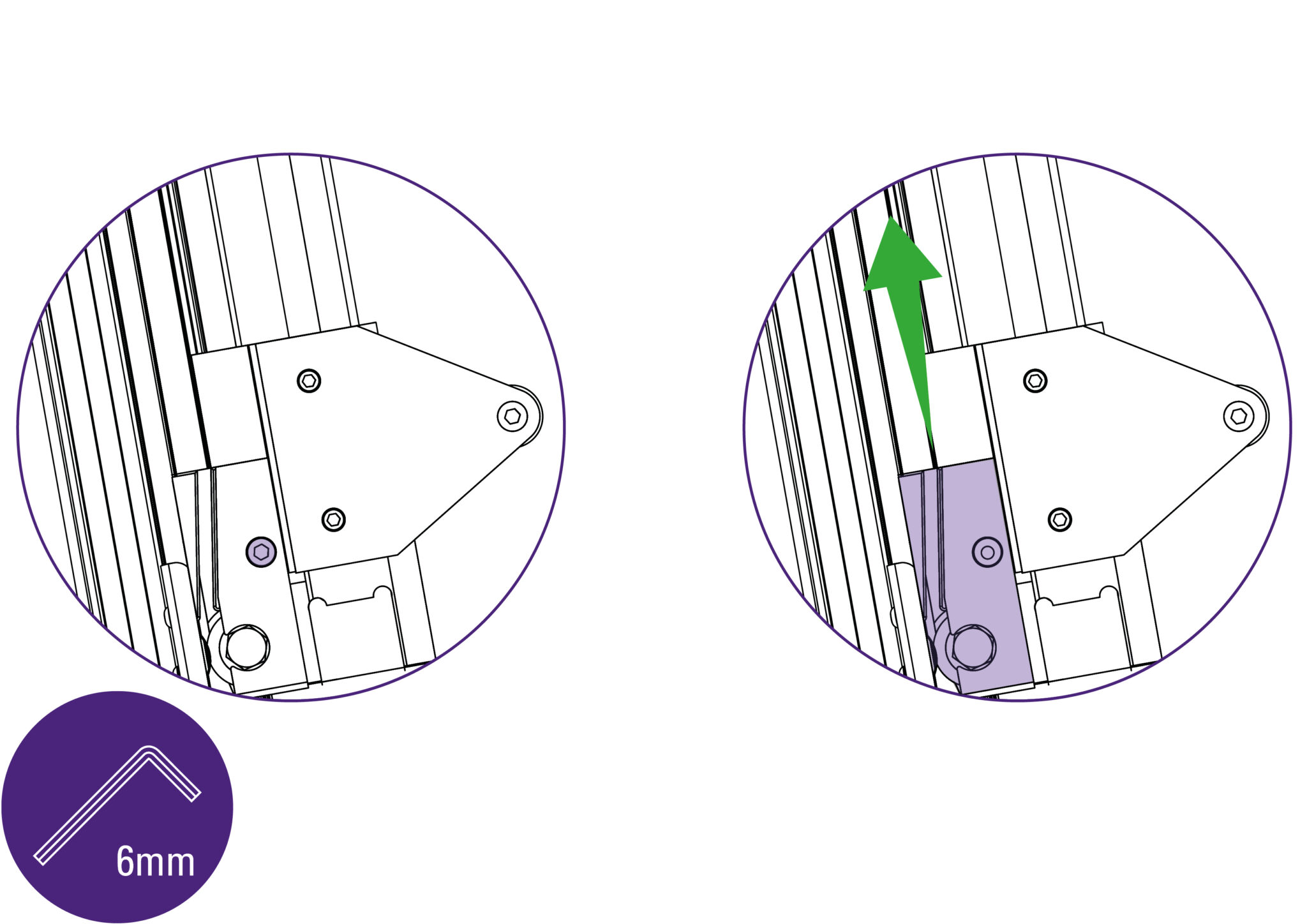
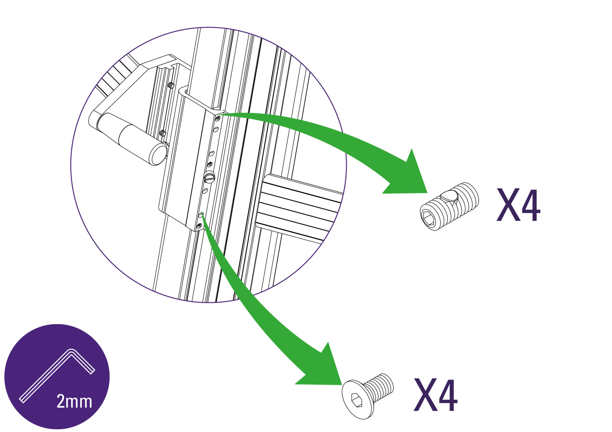
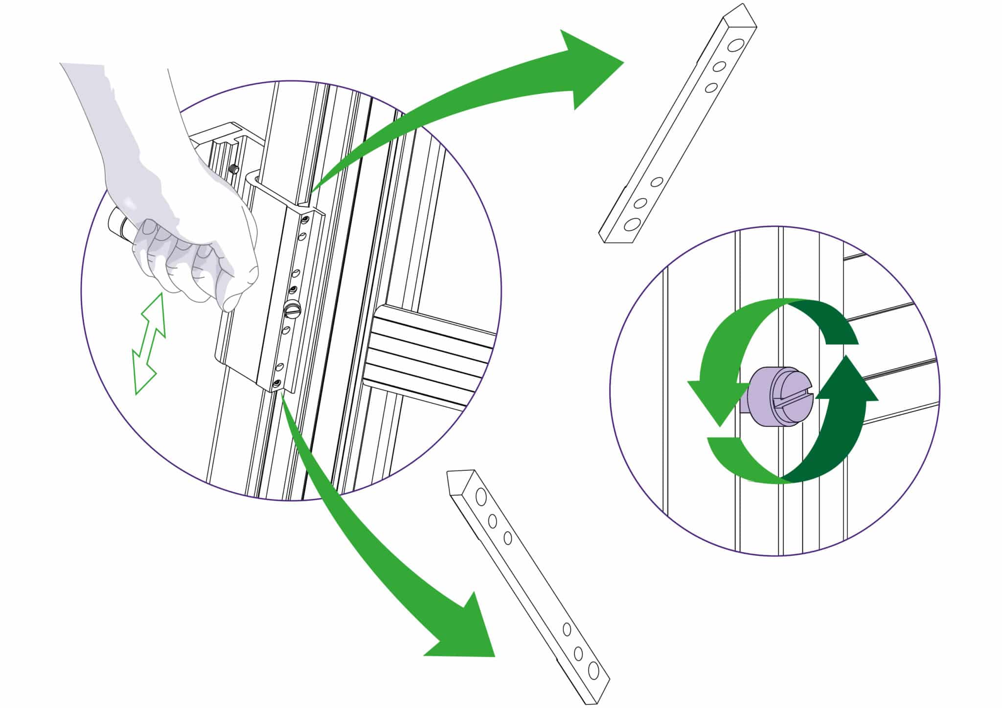
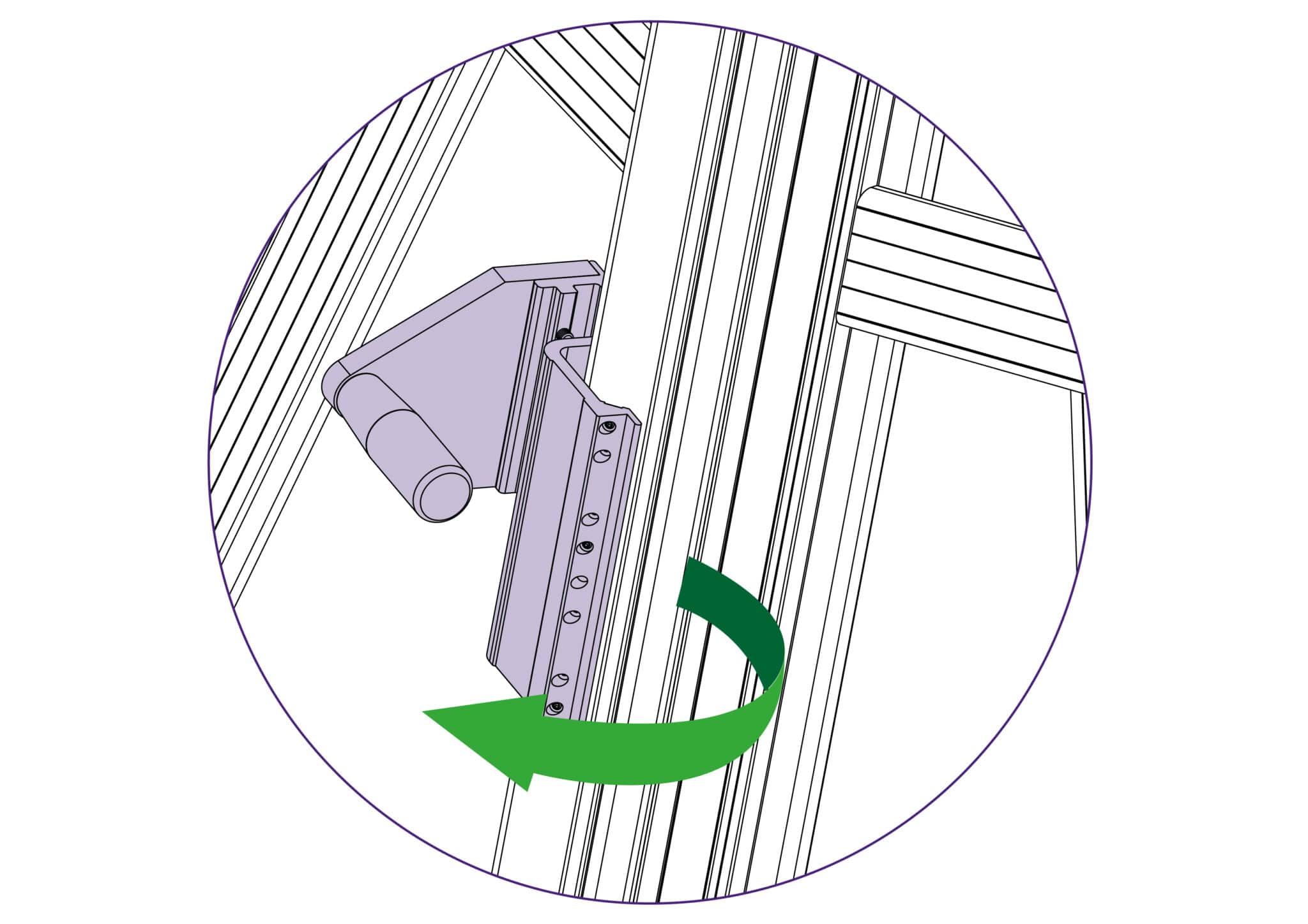
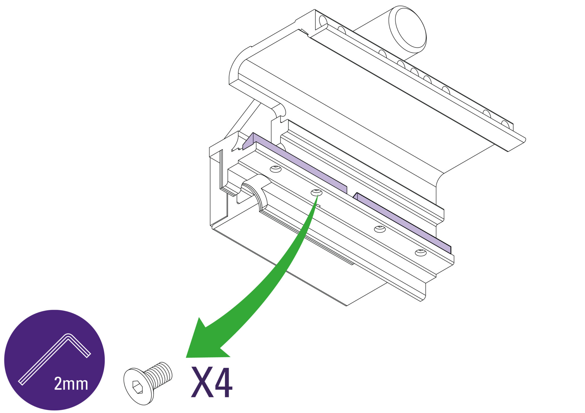
Use a 2mm Allen (Hex) key to remove the screws holding the internal bearings in place.
Reverse these steps to re-install. Refer to Adjusting the sliding bearings> to adjust the sliding fit.
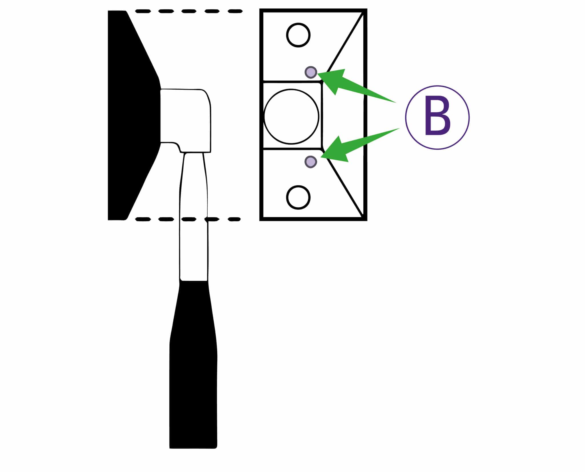
The pressure of the clamp is in relation to the amount of pressure applied to the operating handle. However in time the maximum clamping pressure can reduce due to wear on the friction black (hidden within the machine), compensation for this can be made by adjusting the two small grub screws in the operating handle housing as shown. Turning the screws clockwise will increase the maximum clamping pressure.
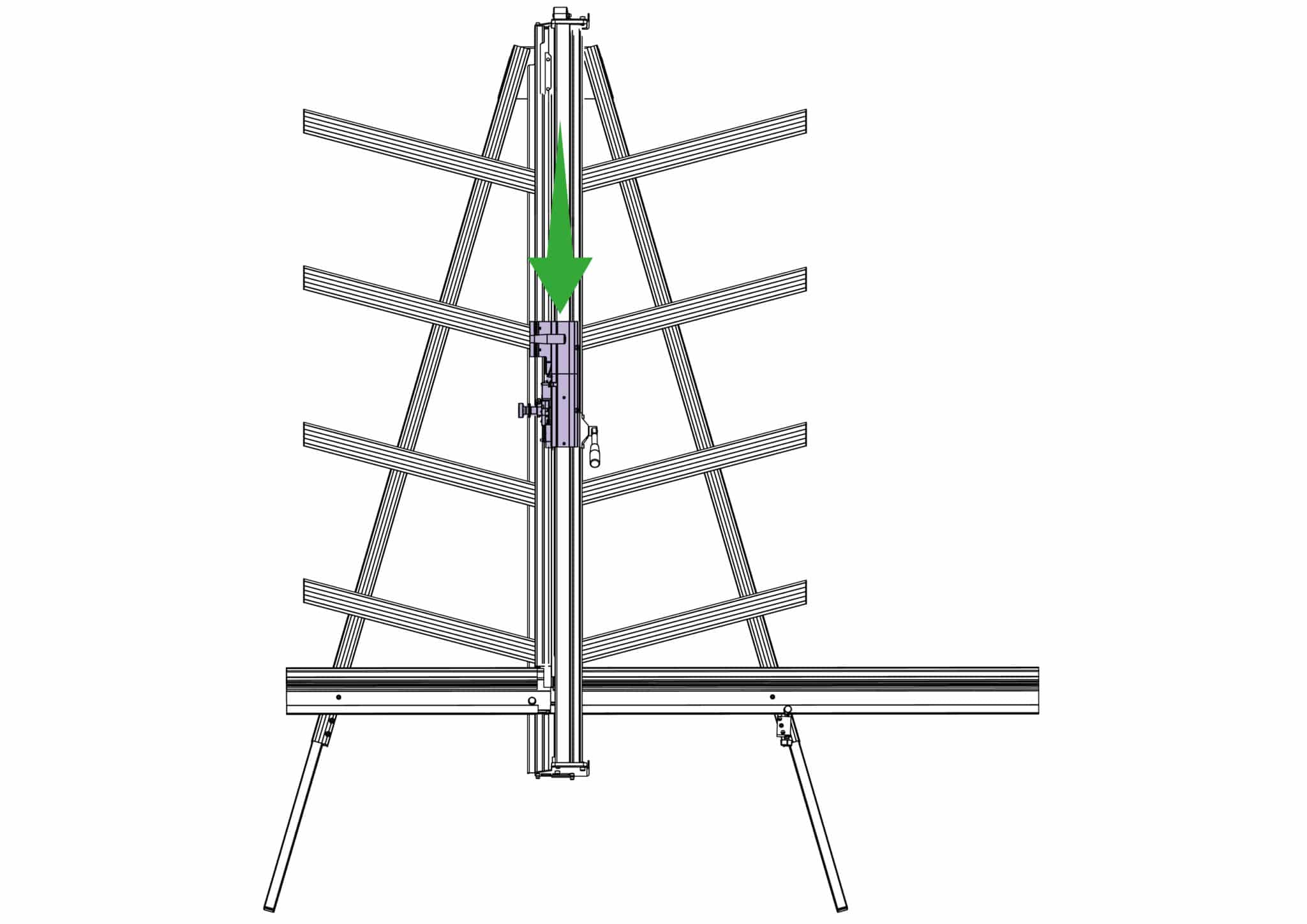
The sightline strip is fixed to the clamp and then trimmed using the cutting blade to give an accurate guide when cutting to trim lines, the edge of an image or pencil marks.
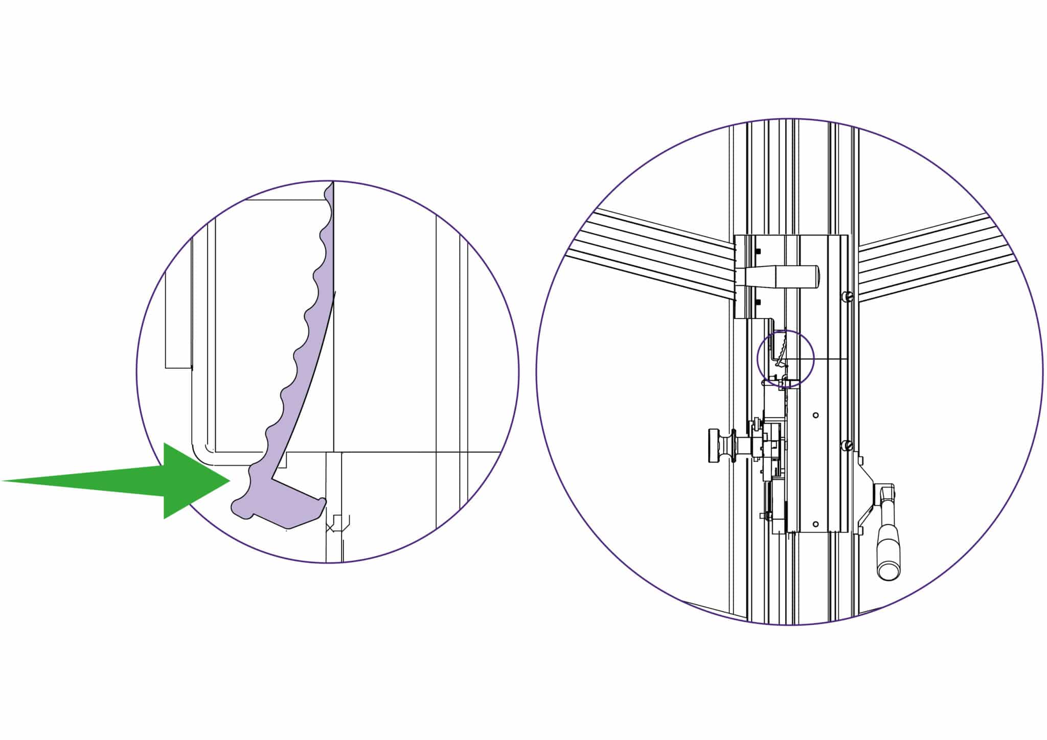
NOTE: Do not engage the twin wheel cutter until after reading its instructions for use in Using & changing the twin wheel cutter>. Engaging the twin wheel cutter interferes with the sightline strip and can cause damage to it. A gap is left in the sightline strip at a convenient height to enable the twin wheel cutter to be engaged.
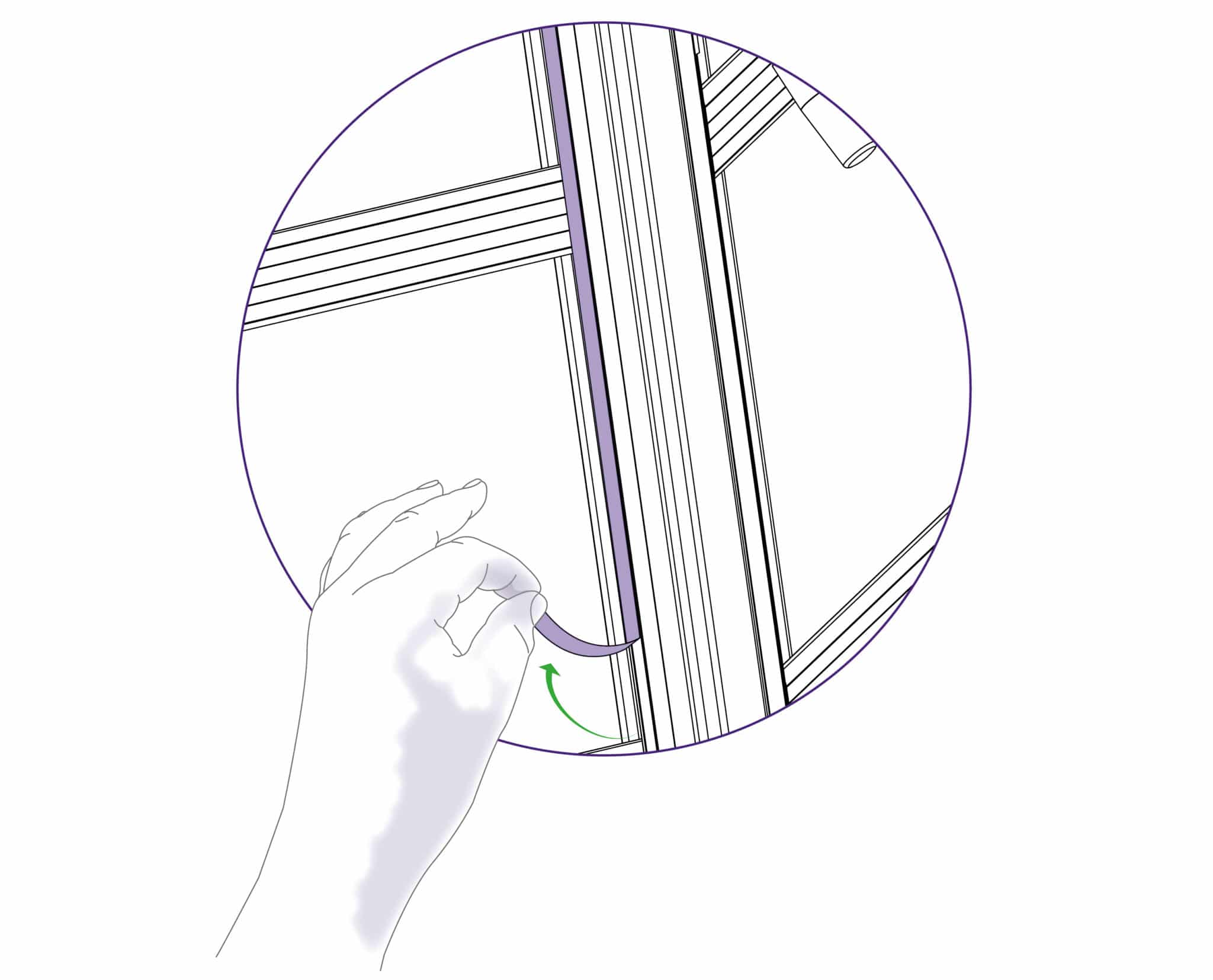
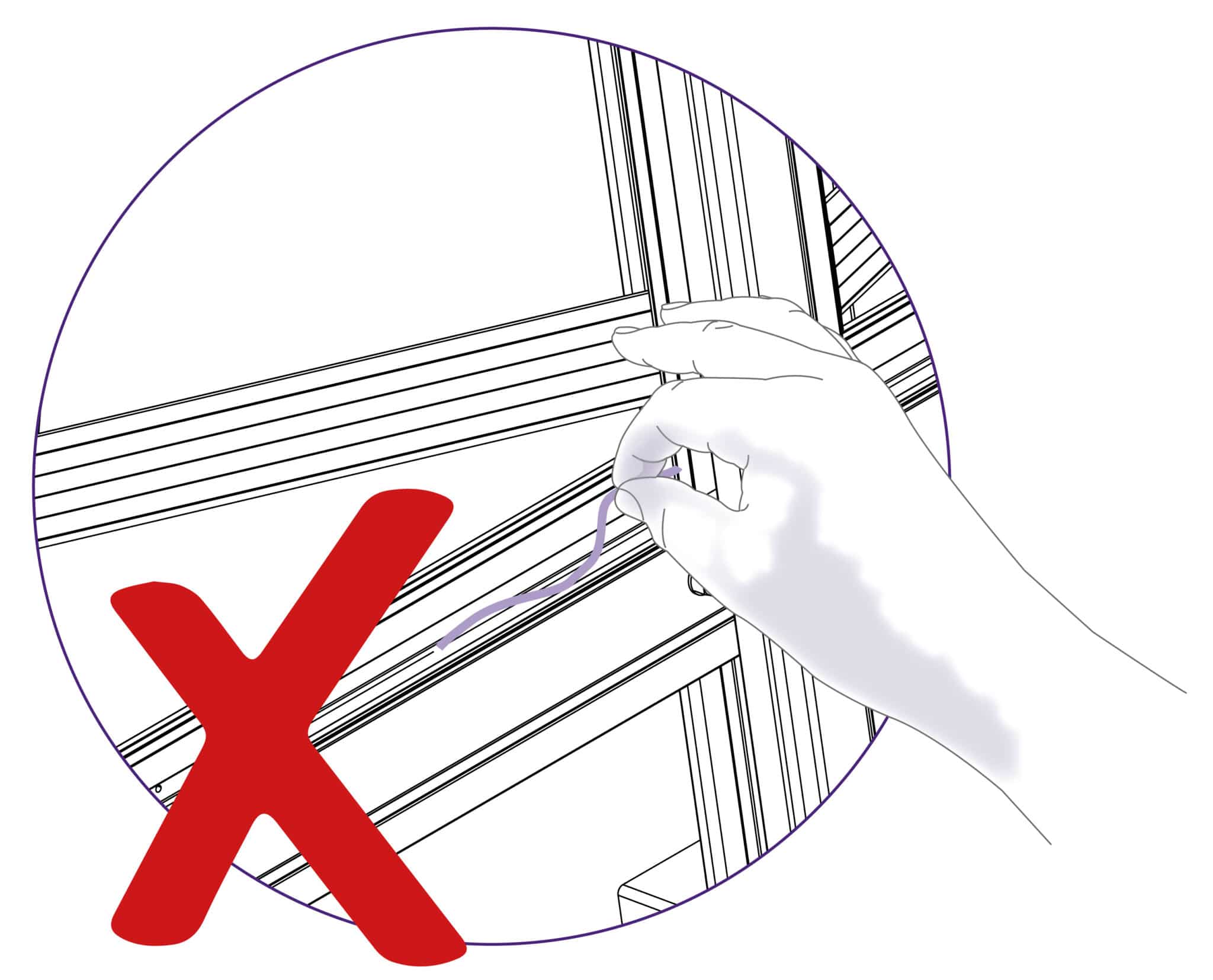
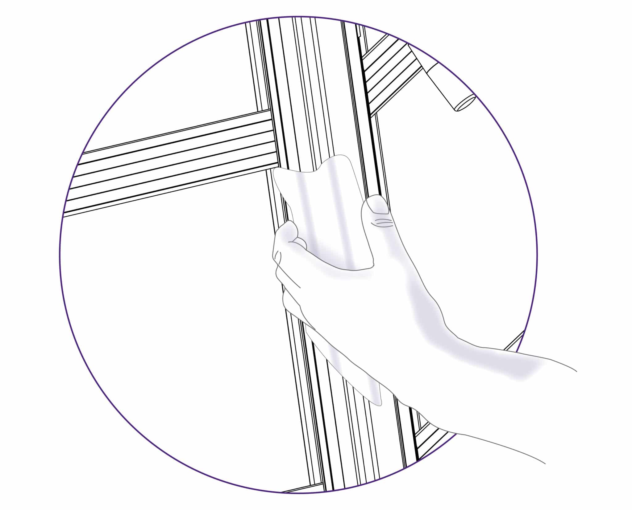
Remove the worn sightline strip by peeling it off and clean any surplus adhesive with solvent cleaner on a cloth. Remove the backing paper and starting at the bottom press the strip firmly in the channel provided working upwards and cut off at a convenient height. Leave a gap of 18cm (7”) and then fit the remainder of the strip.
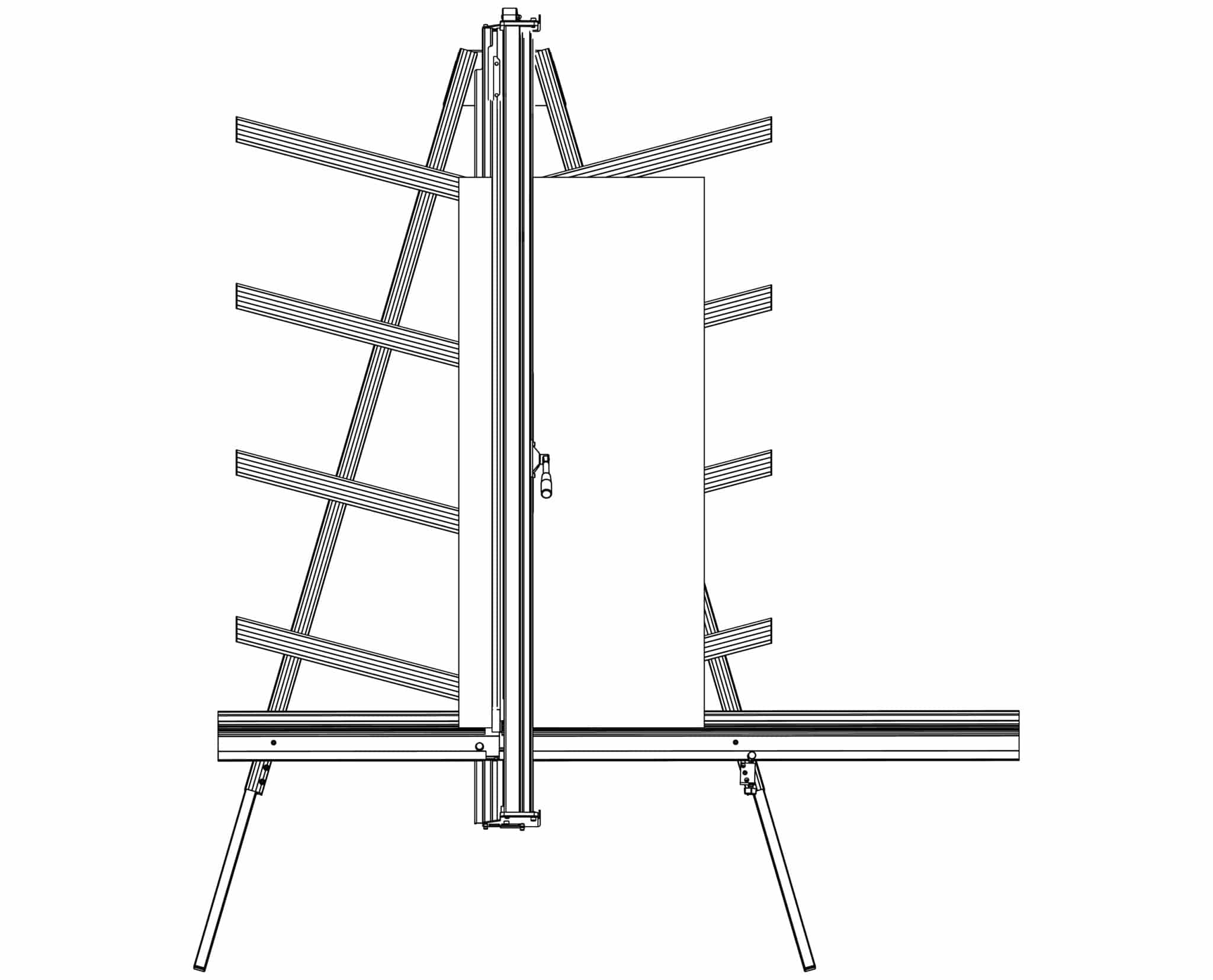
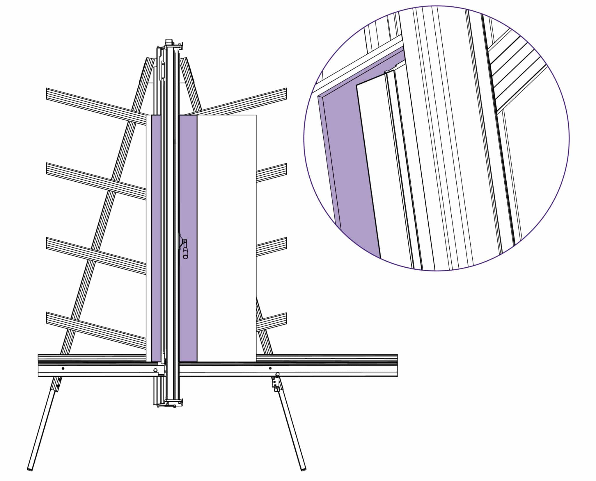
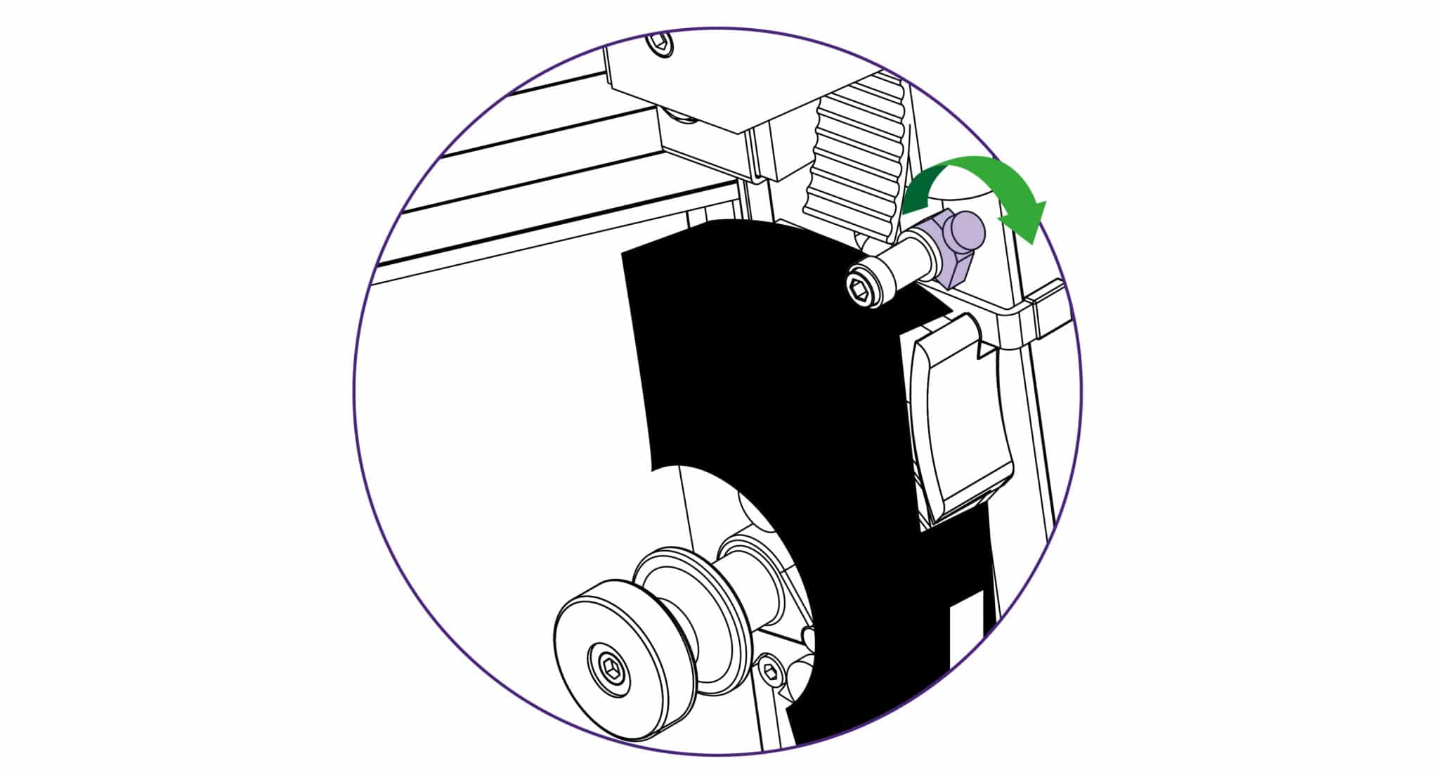
Keep fingers clear and using a block or tool hold down the top left corner of the strip to start the cut. With the turret ratchet disengaged (see Using the scoring blade >) press the blade lightly on to the surface of the sightline strip and score along the full length. Repeat and trim the sightline strip in 2 or 3 cuts.
Attach the balance weight (see The multi-tool cutter and the counterbalance >) to the other cutting head, hold the cutter at waist height and place a 2mm hexagon wrench on the top adjustment screw.
Use a 2mm Allen (Hex) key to remove the screws holding the internal bearings in place.
Reverse these steps to re-install. Refer to Adjusting the sliding bearings> to adjust the sliding fit.
The pressure of the clamp is in relation to the amount of pressure applied to the operating handle. However in time the maximum clamping pressure can reduce due to wear on the friction black (hidden within the machine), compensation for this can be made by adjusting the two small grub screws in the operating handle housing as shown. Turning the screws clockwise will increase the maximum clamping pressure.
The sightline strip is fixed to the clamp and then trimmed using the cutting blade to give an accurate guide when cutting to trim lines, the edge of an image or pencil marks.
NOTE: Do not engage the twin wheel cutter until after reading its instructions for use in Using & changing the twin wheel cutter>. Engaging the twin wheel cutter interferes with the sightline strip and can cause damage to it. A gap is left in the sightline strip at a convenient height to enable the twin wheel cutter to be engaged.
Remove the worn sightline strip by peeling it off and clean any surplus adhesive with solvent cleaner on a cloth. Remove the backing paper and starting at the bottom press the strip firmly in the channel provided working upwards and cut off at a convenient height. Leave a gap of 18cm (7”) and then fit the remainder of the strip.
Keep fingers clear and using a block or tool hold down the top left corner of the strip to start the cut. With the turret ratchet disengaged (see Using the scoring blade >) press the blade lightly on to the surface of the sightline strip and score along the full length. Repeat and trim the sightline strip in 2 or 3 cuts.

Ⓒ Keencut 2020 | Baird Rd, Corby NN17 5ZA UK | Contattaci |
Creato da DeType | Privacy | Clausola di esonero sito web
Politica dei resi |
Seguici


