
SteelTrak User Guide
How to use this guide
Scroll down to view the guide.
You can expand and collapse sections using the + and – icons.
The images in this manual are expandable. Click/tap on them to enlarge.
View PDF version >
Other support resources
Register your cutter to activate your guarantee >
Visit Keencut support centre >
Visit user forum >
Contact Keencut >
This User Guide for the SteelTrak gives advice on cutting techniques, using the different cutting heads and care and maintenance of your machine.
Before using your machine make sure that you have installed and calibrated it correctly. Full details are in the Installation Manual.
Visit the SteelTrak 165 and 210 installation manual >
Visit the SteelTrak 250 installation manual >
The Cutting Head runs up and down the Main Body of the machine on two stainless steel tracks and has zero side movement giving perfect blade control. The Main Body also encloses a balance weight system that allows the Cutting Head to be suspended at any height, benefiting blade changing and maintenance but also minimising the effort required to lift the heavy duty Cutting Head.
There are four cutting functions built into the machine the top part of the Cutting Head houses the Twin Wheel or TW Cutter, the standard Composite TW Cutter is used for cutting tougher materials than a normal blade can handle. Composite boards such as Dibond (r) and other materials including MDF, Masonite and Hardboard up to 4mm thick are all cut with ease in one stroke. The TW cutter can be easily engaged and disengaged at will.
An optional Aluminium TW Cutter is also available for cutting aluminium up to 1.6mm (16swg) and can be attached to the machine in just a few seconds. If you need further advice regarding materials please contact your supplier.
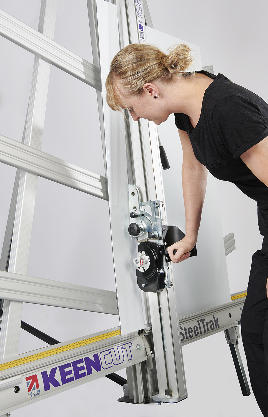
Raise the Cutting Head to chest height, select the cutting tool required and engage it in position ready for cutting. Check the black plastic handle on the Pull Bar is pointing out towards you.
Push the Cutting Head up far enough so the stub shaft on the Pull bar can be twisted to engage in the slot of the handle bracket, and push the Cutting Head to the top of the machine.
Insert the material to be cut into the machine and clamp in position.
Pull down on the Pull bar to cut, the stub shaft is designed so that it locks itself in position when the Cutting head is moved up or down preventing the Pull bar from being able to twist out of place
When the board has been cut as far as the Pull bar will allow, slightly push the Pull Bar up and twist it away from the Cutting Head to disengage it. Raise the Pull bar all the way up to its rest position.
Continue the cut using the Cutting Head handle in the normal way
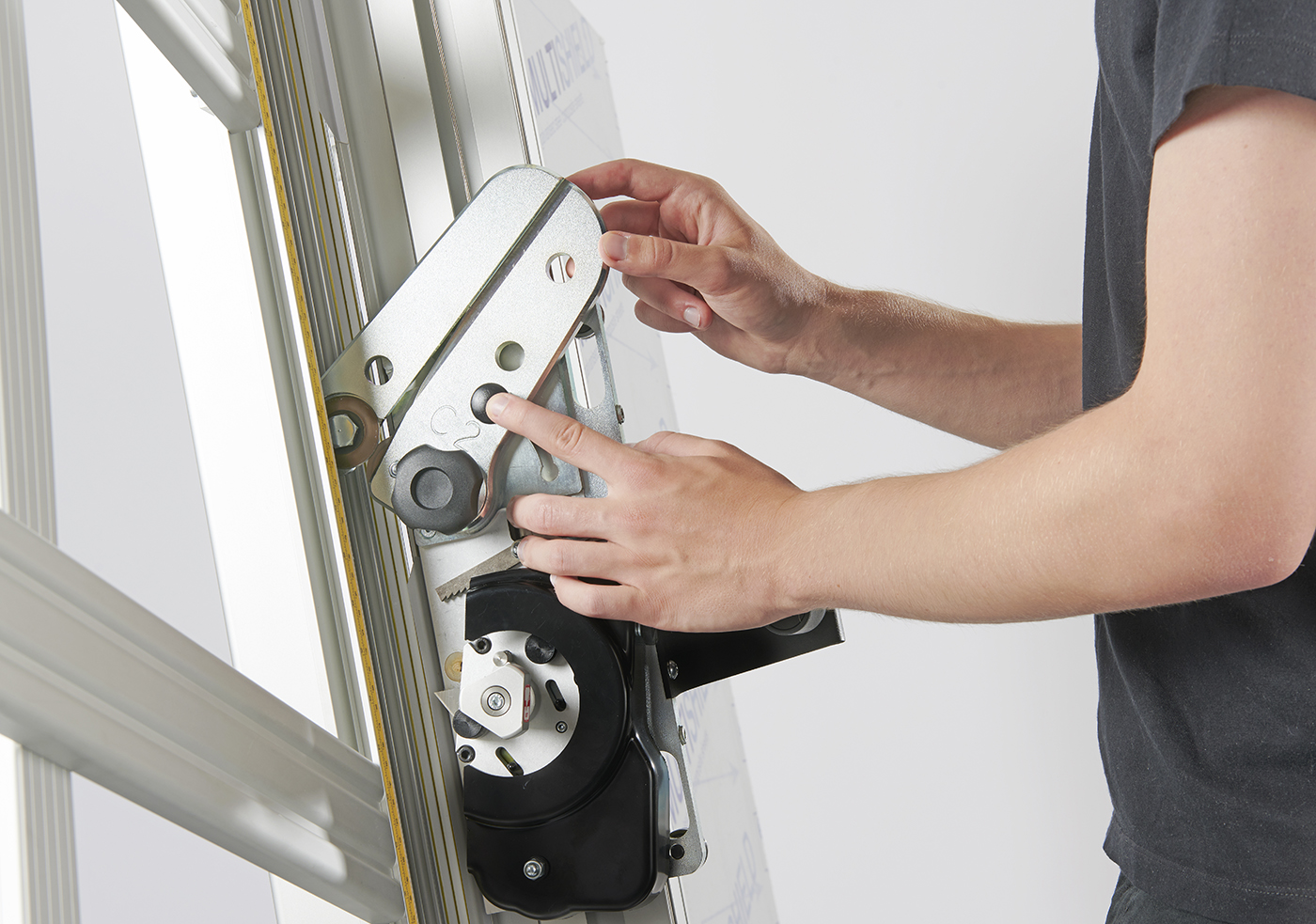
On the lower half of the Cutting Head is the Multi-Cutter Head housing three instantly selectable cutting tools. To change between the cutting tools just pull the Turret Handle out to the left and rotate it one third of a turn until the indicating label shows which cutter is active.
The Multi-Cutter Head also incorporates the unique Keencut Ratchet System which gives two main advantages. Firstly, it enables thick, tough materials to be cut in multiple passes by setting the ratchet to cut through the board in stages giving the best cut quality achievable and reducing operator effort to suit the operator. Secondly, it locks the cutting blade at the required depth and holds it there mechanically so concentration can be applied to pushing the blade through the material without having to worry about applying effort to hold the blade in the material. Once the blade reaches the bottom of the cut it the ratchet is automatically disengaged and the Cutting Head moves out to its rest position ready to be set for the next cut
The Clamping system enables the operator to control the grip pressure by means of an integral friction brake that maintains the clamping force at the pressure applied by the operating lever. Soft materials can be held firmly without sustaining damage and solid materials held rigidly without movement.
For soft materials such as Foamcore boards, lightweight card, etc… you can use medium pressure. The underside of the clamp grips an area nearly 4cm (1 1/2″) wide with non-marking sponge rubber. Reasonable force can be applied.
if in doubt clamp a sample first with the good surface facing outwards.
For harder materials such as PVC foam board, MDF or Composite boards such as Dibond Use medium to heavy pressure.
For cropping to trim lines, pencil marks, etc… place material in approximate position under clamp, apply light clamp pressure to allow the material to be repositioned. Align the trim marks with the edge of the Sight-line strip and clamp
Cleaning - Keencut design machines to be as maintenance free as possible, however we do recommend regular cleaning. Do not wipe the squaring arm channels or remove any debris with fingers, as it may contain sharp particles such as glass. Use a vacuum cleaner if possible or if a soft brush is used, work slowly and do not allow particles to flick off of the bristles.
Lubrication - It is important that the correct lubrication is used as ordinary oils and solvents can adversely affect plastics, the diagram above shows the best lubricants for the various parts of the machine. Do not use penetrating oils for lubrication on this machine.
Wipe the guide rods and rollers using cleaning solvent on a cloth, and lubricate the surfaces very lightly with petroleum jelly. The axles of the rollers are lubricated and sealed for life and need no further attention.
Use a light oil (3 in 1) on the ratchet system, one or two drops on the pivot point and one drop on the
ratchet teeth
Silicon Lubricant can be sprayed in from the top of the balance weight opening whilst the cutting head is parked at the top of the machine
Smear edge with petroleum jelly on the ratchet release bar
Smear Petroleum jelly (Vaseline) around curved slot on the Swinging Arm
The pressure of the clamp is in relation to the amount of pressure applied to the operating handle. However in time the maximum clamping pressure can reduce due to wear on the friction block (hidden within the machine), compensation for this can be made by adjusting the two small grub screws in the housing as shown. Turning the screws clockwise until they stop moving them undoing them one full turn should give an acceptable pressure, but further small adjustment can be made to increase or decrease the pressure as required. Care should be taken not to tighten either grub screw fully or this will result in undue wear of the friction plate.
When cutting tough materials it is essential that the clamping system operates at its' optimum, the moving clamp bar must press evenly onto the board being cut and not clamp it only at the top or bottom.
Open the clamp by at least 1-2mm and remove the plastic cover strip situated above the clamp handle it just
clips out of place, use the end of a small steel rule to lever it from its’ groove.
The clamp adjuster is at the top end of the push rod and is locked in position by two locking nuts.
The silver nut has a normal right-handed thread, slacken it using a 10mm wrench by turning it counter-clockwise when looking from below.
Now slacken the black nut, this has a left hand thread and should be turned clockwise when viewed from below.
The ‘adjuster’ is the hexagonal bar between the two nuts, by turning it with the spanner it alters the clamps
alignment with the back of the machine.
Rotate the adjuster whilst observing the clamp from the side and bring the clamp into parallel
To check for parallel use 2 pieces of A4 paper, place one under the bottom end of the clamp and hold the
other at the top end whilst depressing the clamp handle, check that the clamp firmly grips pieces of paper
Tighten the two locking nuts whilst holding the adjuster in position with the second spanner, then operate the clamp a few times, check and adjust further if necessary.
Finally, replace the plastic cover strip.
The Cutting Head slides up and down on two stainless steel Guide Rails (1) that are embedded into the Slideway
There are four grooved Guide Wheels that run on the rails, the two furthest away are fixed (A) and the two closest are adjustable (B). These Guide Wheels are adjusted in the factory and should not under normal circumstances require re-adjustment.
The adjustment check and procedure is listed in the event that the Cutting Head needs to be removed for any reason
The steel bar with the oval holes, the Spring Block (4), holds the two adjustable wheels and is designed to flex, a small amount, like a spring and add tension so the Guide Wheels are pressed onto the Rails. It is important that the tension is set correctly, use a 0.15mm (0.006″) feeler gauge or a stout piece of paper to measure the gap under the Spring Block as shown. If the gap is too large or too small the adjacent wheel will need adjusting.
The Shafts that the adjustable wheels run on are eccentric and move the wheel into or away from the rail as it is rotated.
Using a 13mm spanner on the Locking Nut and a 5mm spanner (or grips) on the square end of the Shaft hold the Shaft still and loosen the Locking Nut by about half a turn.
Rotate the Shaft clockwise whilst using a feeler gauge or paper as above to measure the gap under the Spring Block. If the Shaft will not rotate any further and the correct gap has not been achieved, turn it anti-clockwise and the correct adjustment should be obtained within one full rotation of the Shaft.
When the correct gap appears hold the Shaft still and tighten the Locking Nut.
This User Guide for the SteelTrak gives advice on cutting techniques, using the different cutting heads and care and maintenance of your machine.
Before using your machine make sure that you have installed and calibrated it correctly. Full details are in the Installation Manual.
Visit the SteelTrak 165 and 210 installation manual >
Visit the SteelTrak 250 installation manual >
Ⓒ Keencut 2020 | Baird Rd, Corby NN17 5ZA United Kingdom | Contact us
Created by DeType | Privacy | Website Disclaimer | Terms & Conditions