

SteelTrak 165 and 210 Installation Manual
How to use this guide
Scroll down to view the guide.
You can expand and collapse sections using the + and – icons.
The images in this manual are expandable. Click/tap on them to enlarge.
View PDF version >
Other support resources
Register your cutter to activate your guarantee >
Visit Keencut support centre >
Visit user forum >
Contact Keencut >
You will need approximately 2 hours to install and calibrate your cutter
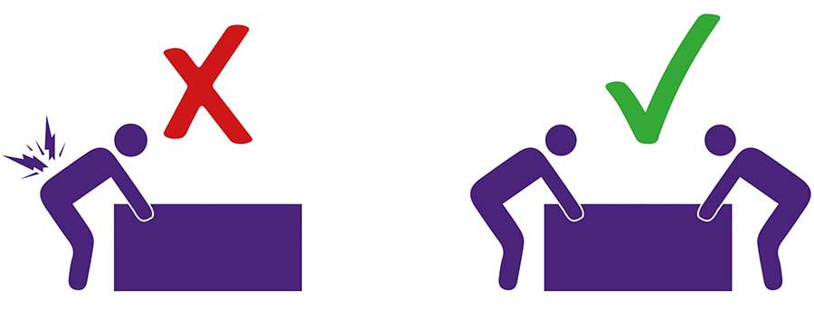
To prevent injury and damage, lift the box and the machine with 2 people


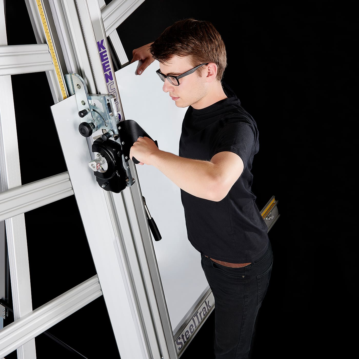
The first stages of assembly are carried out with the machine laying on the floor
NOTE : When taking the machine from the box, ensure at least two people are lifting. Remember to bend your knees and keep your back straight – this machine is heavy.
| Be careful when lifting |
Slacken the bottom two screws on both legs and extend the telescopic leg to the desired length. (This can be re-adjusted later). Tighten the screws to clamp in position.
Once you are happy, swing both legs out as far as they will go.
Remove the screw and spacer from each leg
Lay the squaring arm flat adjacent to the machine and slide it through the gap in the main body so that the two holes in the centre align with the 2 holes in the spine.
IMPORTANT: The screws MUST be inserted tightened in this order.
Insert the countersunk screw into to the squaring arm, use a 5mm Allen (Hex) key to tighten the screw firmly.
IMPORTANT: Ensure that this is tightened as much as you possibly can using the short end of the Allen (Hex) key (as shown). If this screw is not tightened enough, the squaring system will not work.
| Do this firmly |
Bring the strut into position at the top of the machine so the angled section is pointing to the top of the machine, and the recess is facing the back of the machine (as shown).
Insert the countersunk screw into to countersunk hole on the spine and into the strut, use a 5mm Allen (Hex) key to tighten the screw firmly.
IMPORTANT: Ensure that this is tightened as much as you possibly can using the short end of the Allen (Hex) key (as shown). If this screw is not tightened enough, the squaring system will not work.
| Do this firmly |
Align the hole at the bottom of the strut with the highlighted hole in the squaring arm. Insert the countersunk screw into to the squaring arm, use a 5mm Allen (Hex) key to tighten the screw firmly.
IMPORTANT: Ensure that this is tightened as much as you possibly can using the short end of the Allen (Hex) key (as shown). If this screw is not tightened enough, the squaring system will not work.
| Do this firmly |
Check that these three screws have definitely been tightened fully.
Note: lifting the long end of the squaring arm could release some pressure on the screws and allow for further tightening
DO NOT PROCEED IF YOU HAVE NOT FULLY TIGHTENED THE 3 SCREWS HIGHLIGHTED ABOVE
Insert the countersunk screw into to the squaring arm on the left side of the slideway, use a 5mm Allen (Hex) key to tighten the screw firmly into the spine.
IMPORTANT: Ensure that this is tightened as much as you possibly can using the short end of the Allen (Hex) key (as shown). If this screw is not tightened enough, the squaring system will not work.
| Do this firmly |
Take the screws and spacers that came from the legs and insert them into the highlighted holes in the squaring arm.
Align them with the holes in the legs and tighten with a 5mm Allen (Hex) key.
| Do this firmly |
The SteelTraK 165 offers a fast, accurate and robust way to cut boards measuring up to 165cm (65”). The SteeltraK 210 utilises a ‘Pull Bar System’ to increase the cutting length to 210cm (82”) without compromising the straightforward way the SteelTraK cuts medium size boards. The ‘Pull Bar’ is only used when cutting between 165cm and 210cm and is automatically stowed out of the way when not in use by virtue of its integral spring balance
At any stage of the assembly before standing the machine up, fit the Pull Bar using a 6mm Allen key:
Remove the Screw and Stub Shaft from the end of the Pull Bar.
Insert the end of the Pull Bar in the bracket as shown ensuring the handle at the other end is facing in the correct direction.
Insert the Screw and Stub Shaft and tighten.
If you are going to fit the Free Standing Kit (optional) to a SteelTrak 165 go to Fitting the Free standing kit (165 only)>
If you are going to fit the Free Standing Kit (optional) to a SteelTrak 165 go to Fitting the Free standing kit (210 only)>
IMPORTANT: Ensure the wall is stable and use the appropriate fixings.
Using 2 people, lift the top end of the machine (place it on a strong stool or chair) and fit the two M8 screws (supplied separately) through the black Top Bracket into the back of each of the legs. Use a 5mm Allen (Hex) key to tighten these and the adjacent two screws (four screws in all) to fix the Legs to the top of the Main Body.
| Do this firmly |
| Be careful when lifting |
Fit the Wall Mounting Bracket to the top of the Main Body, fasten the screws finger tight only.
| Do this gently |
Get help to lift the machine up and position it against the wall in the desired position.
| Be careful when lifting |
The Wall Mounting Bracket should lay flush against the wall. Mark the position of the two V’s on each side of the bracket with a short pencil.
Move the machine away and remove the Wall Mounting Bracket.
Attach the bracket to the wall in the marked position with appropriate fixings then reposition and fasten the machine to the bracket.
NOTE: The Free standing kit is an optional extra and does not come packed with the main machine. Assistance will be needed to fit the Free Standing Kit
Extend the telescopic leg to the same length as the front legs less 12cm (5″)
Get help to hold the machine vertical and attach the bracket to the top of the machine using the nuts and screws provided.
| Be careful when lifting |
Swing down the stay and attach the fixing block to the plate on the bottom of the Main Body, tighten all three screws on the stay using a 6mm Allen (Hex).
Adjust the telescopic leg so the machine stands evenly as shown.
Secure the top of the Legs to the Main Body by fitting the two M8 screws (supplied separately) through the black plate into the back of each of the Legs, tighten these together with the adjacent two screws (four screws in all) to fix the Legs in position with a 6mm Allen (Hex) Key.
Attach the bracket to the end of the Squaring Arm as shown using the two bolts provided.
Adjust the telescopic leg so the machine stands evenly as shown.
Separate the Supports into left hand and right hand.
The screws fit into special grooves in the underside of the Supports. The grooves have teeth on their sides to match the teeth of the screw thread, the screw can be fitted in the groove anywhere along its length but be careful to make sure the screw is kept perpendicular to the Support and not screwed in out of line
Place one of the 16 Long Screws in each of the holes along the legs of the machine, use a 4mm Allen (Hex) Key to fix each Support in turn ensuring the ends of the Supports are firmly against the Main Column and the screws are aligned with the special grooves as explained above.
Fix the end of each Support in position with the Brackets and short screws as shown.
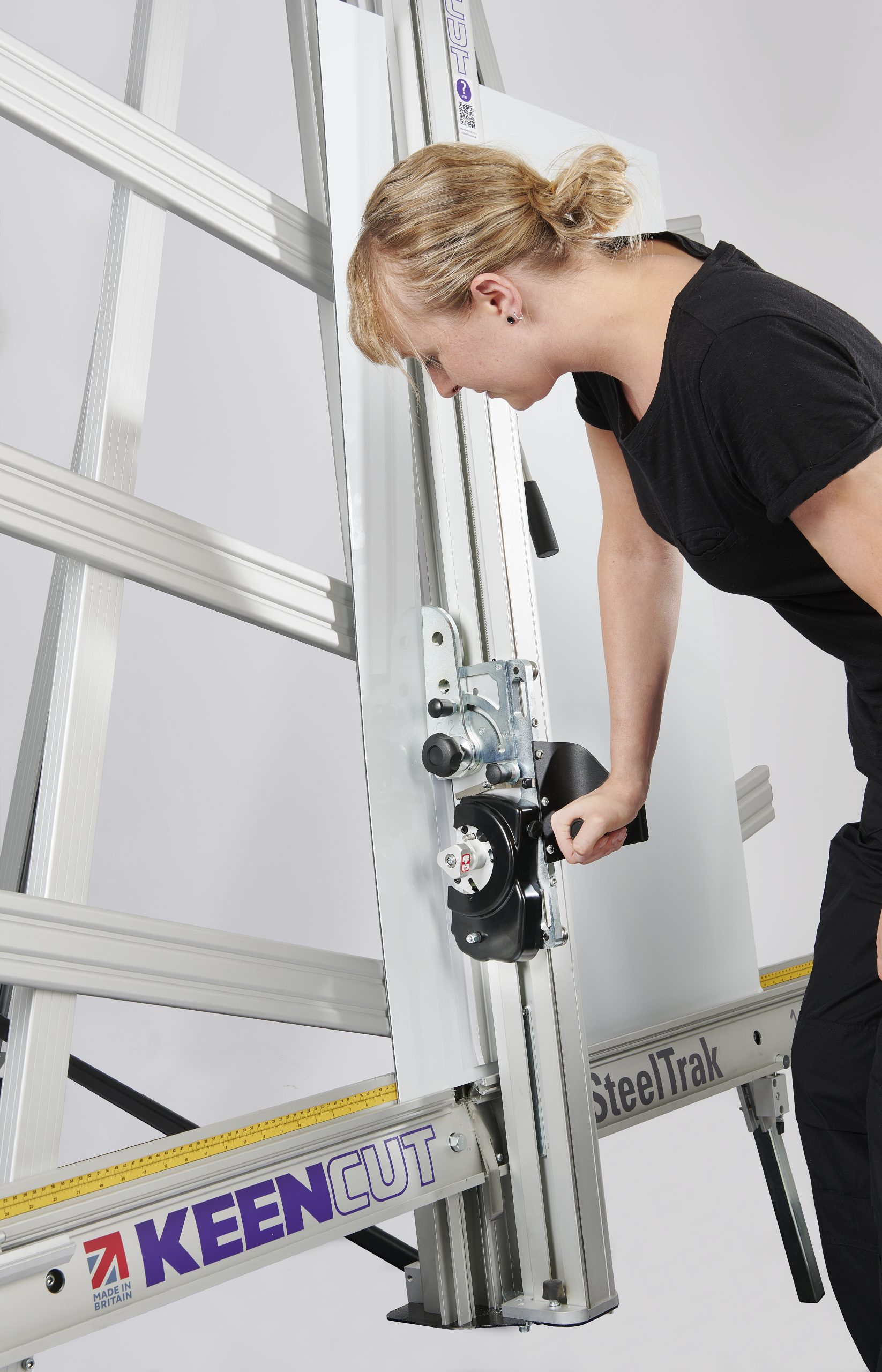
Remove the three screws from the top of the Cutting Head and fix the Handle in place using a 4mm Allen (Hex) Key.
Ensure it is the correct way around (as shown). Move the cutter head to the middle of the Main Body
For your machine to produce accurate square cuts the Squaring Arm needs to be fixed at exactly 90° to the Main Column. This is pre-calibrated by Keencut, and will be applied if the assembly process has been completed correctly. To check the accuracy and ensure the machine has been assembled correctly, you can run this test.
select a sheet of foam core or foam board (3-6mm) at least 60cm x 100cm (24” x 36”) in size. The larger the board the greater the accuracy.
Place the board on the machine vertically as shown and apply the clamp ensuring the bottom edge is in firm contact with the Squaring Arm.
Select the cutting blade on the rotating cutting head (see section 6). Cut into the top of the board to produce a cut approximately 3cm (1″) long. Disengage the cutter using the cutter release lever. Lower the cutter and make a similar cut at the bottom of the board by pressing the blade through the board about 3cm (1″) from the bottom edge of the board.
Unclamp and turn the board around and place it back in the SteelTrak but do not clamp it.
IMPORTANT: For the test to work the board must be turned laterally (like a page in a book) not top to bottom.
Move the sliding head down and align the board so that the cutting blade enters the previous made cut at the bottom edge of the board. Apply the clamp. Release the blade.
Raise the sliding head and depress the blade so that it engages with the top edge of the board, should enter the same cut as made previously showing that it is square.
If it does not, please note that the deviation witnessed is DOUBLE the actual deviation, if the gap between the 2 cuts is 2mm or less, this is within the specified tolerance.
If for any reason please refer to Troubleshooting if machine is not square >
Take a small piece of board and accurately measure its’ height, place the board in the machine such that it lays over the groove where the scale is to be applied.
With a pencil, mark a fine line level with the top edge of the board adjacent to the groove.
Remove the release paper from the groove in the Main Body and stick the Vertical scale in place such that the pencil mark lines up with the measured dimension in (1).
Slide the two Measuring Stops onto the Squaring Arm being careful to align the profile of the stop and its locking bar to the profile of the Squaring Arm. The Measuring Stops are able to ‘flip’ in and out as required.
Set both stops at 15cm (6″), ‘flip’ one of the stops into place and the other out, then place a piece of card in the machine and slide it to touch the stop that is flipped in. Clamp the card in place select the cutting blade on the rotating cutter head and cut the card.
Measure the cut width of the card, say it is 14.7cm (5 7/8″), slide the Measuring Scale so that it reads the dimension measured i.e. 14.7cm (5 7/8″). Repeat the process with the other Measuring Stop.
NOTE: The Sightline Strip is fitted to your machine but may wear or get marked with use. A spare strip is included with the machine, replacement strips are available from your distributor
The Sight-line strip is fixed to the clamp and then trimmed using the cutting blade to give an accurate guide when cutting to trim lines, the edge of an image or pencil marks.
NOTE: Do not engage the Twin Wheel Cutter until reading its instructions for use in the SteelTrak User Guide >. Engaging the Twin Wheel Cutter interferes with the Sight-line Strip and can cause damage to it. A gap is left in the Sight-line Strip at a convenient height to enable the Twin Wheel Cutter to be engaged
Remove the worn Sight-line Strip by peeling it off and clean any surplus adhesive with solvent cleaner on a cloth. Remove the backing paper and starting at the bottom press the Strip firmly in the channel provided working upwards and cut off at a convenient height. Leave a gap of 18cm (7”) and then fit the remainder of the strip. For the 210 version one full length Strip and one cut in half will be required.
Place a piece of firm board up to 6mm (1/4″) thick on the machine to bridge the gap running down the back of the Main Body, this needs to be the full height of the clamp.
Place a piece of card or foamboard 3-6mm (1/8″-1/4″) thick under the full length of the flexible part of the Sight-line strip, not under the aluminium clamp itself. Depress the clamp handle so that the Sight-line strip is pressed flat across the surface of the board.
Keep fingers clear and using a block or tool hold down the top left corner of the strip to start the cut. With the turret rachet disengaged (Scoring page 6) press the blade lightly on to the surface of the Sight-line strip score along the full length. Repeat and trim the Sight-line strip in 2 or 3 cuts
NOTE: If a board is not available to go the full length of the clamp use two or more pieces or trim the strip in stages.

Registering your SmartFold machine will activate your 5 year guarantee.
See the Evolution3 SmartFold User Guide for advice on cutting techniques, using the different cutting heads and care and maintenance of your machine.
Visit the SteelTrak User Guide >
You will need approximately 2 hours to install and calibrate your cutter
To prevent injury and damage, lift the box and the machine with 2 people
Ⓒ Keencut 2020 | Baird Rd, Corby NN17 5ZA | +44 (0) 1536 263158 | Créé par DeType | Confidentialité | Avis de non-responsabilité du site Web | Politique de retours