
How to replace the pivot housing assembly on the SteelTrak 250 only
To do this you will need the SteelTrak & Excalibur pivot housing assembly >
Tools required:
- Allen (hex) key 4, 5 & 6mm
- Small flat screwdriver or steel rule
- 10mm open ended spanner/wrench
- Hand protection
- Steps to access the top of the machine
What to do
NOTE: A minimum of two able bodied people are required to carry out this work. The cutter bar and cutting head need to be removed. It is also important for the instructions to be read and understood before commencing.
The instructions below assume the SteelTrak remains in its vertical installed position for the replacement. However, if preferred the machine can be disconnected from its wall bracket and laid on the floor to work on.
- Remove all blades from the cutting head then to remove the cutting head, loosen the top and bottom handle bracket screws by four full turns using the 4mm Allen (hex) key. Do not loosen the middle screw. Loosen the two spring bar fixing screws by four full turns using the 5mm Allen (hex) key. The cutting head should now come loose on the cutter bar and can be carefully moved to the left to disengage it. The Balance Weight Cable will still be attached and prevent it from falling but do not let go of the cutting head, keep it fully supported at all times.
- Disconnecting the cable will require two people and a pair of steps or a ladder to enable access to the top left hand side of the machine.
- Position the steps or ladder as explained above.
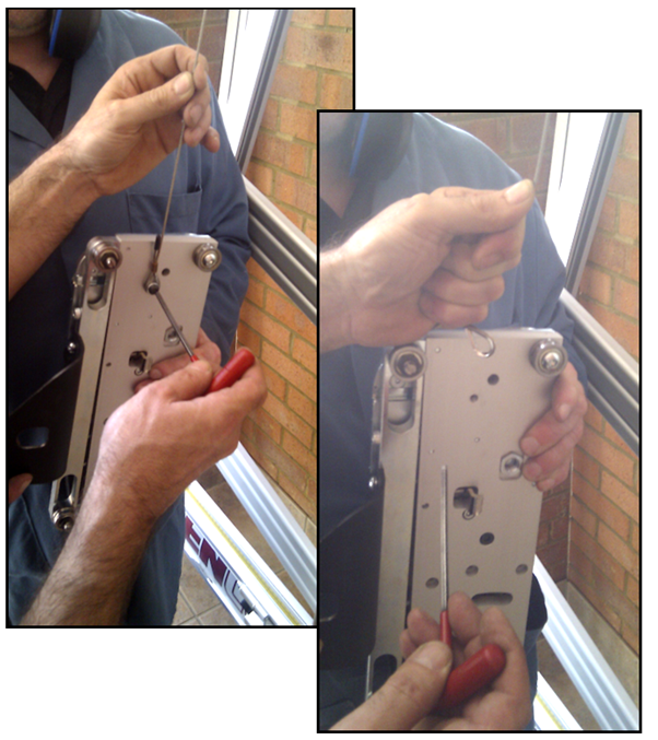
- One person to hold tightly onto the cable and take the weight of the balance weight whilst the other supports the cutting head and uses a 4mm Allen key to remove the screw, washer and spacer attaching the loop at the end of the balance weight.
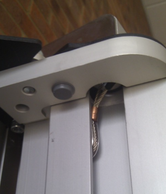
- Whilst holding onto the balance weight cable allow it to slowly retract so it sits in the circular cut out at the top of the slideway.
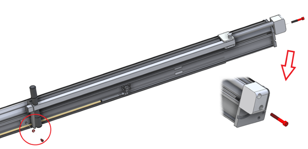
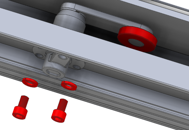
- Disconnecting the cutter bar; one person must hold the cutter bar onto the machine whilst the other removes the following screws.
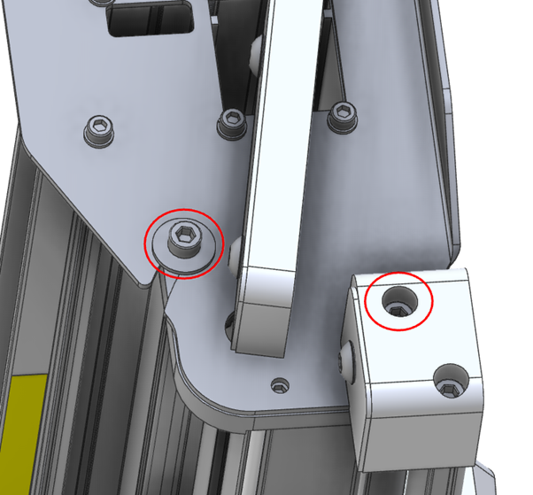
- Using a 6mm Allen key remove the two screws circled red that hold the slideway to the top plate, be sure to remove the flanged washer also.
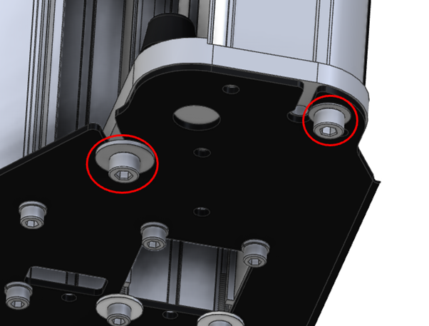
- Repeat this at the bottom of the slideway.
The cutter bar assembly is very heavy and should only be lifted by two people
- Take the weight of the cutter bar and pull it out at the bottom to clear the fixing plate then lower it to the ground. Be careful that end of the balance weight cable is not caught in the top of the cutter bar.
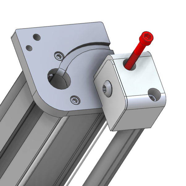
- Return the top screw to add support to the top end of the pull bar but do not tighten. Lay the whole assembly on a large sturdy work surface to continue.
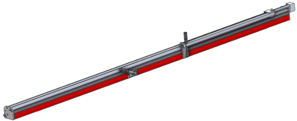
- Using a small screwdriver or steel rule, prise off the black plastic cover strips that are fixed on the right-hand side of the cutter bar. (Shown in red)
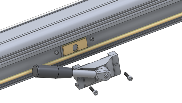
- Remove the clamp handle housing, using a 5mm Allen (hex) key undo the two screws and pull off the assembly ensuring the inside face of the housing points upwards as you do so to prevent internal parts falling to the floor.
- Using the 5mm and 6mm Allen (hex) keys remove the pull bar assembly, this will still be connected by its balance weight cord, there is no need to disconnect this.
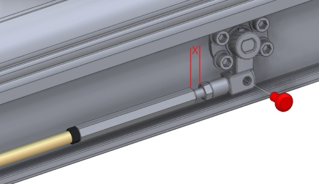
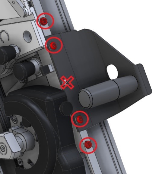
- At the top of the push rod there is an adjuster which aligns the main clamp bar, measure and note dimension X. Pull the pin out of the forked fitting and loosen the two locking nuts (the black one has a left-hand thread) using a 10mm open ended spanner/wrench.
- Rotate the Adjuster to close the gap between itself and the forked fitting as much as possible, sometimes this can be done using your fingers rather than the spanner/wrench.
- Remove the pin from the lower forked fitting.
- Remove the push rod, on some versions the push rod may need to be flexed slightly to remove it.
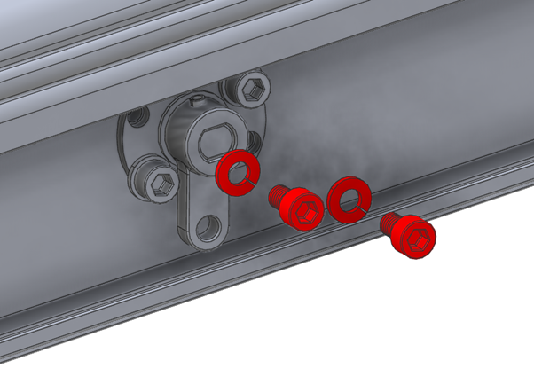
- Remove two of the screws and locking washers from both pivot housing as shown (it is important it is the two shown) using a 4mm Allen (hex) key.
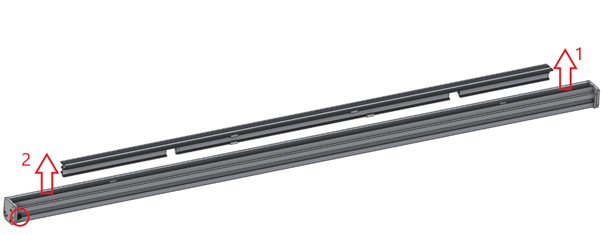
- Turn the cutter bar so the clamp bar is facing upwards. Grip the clamp bar in two hands and pull the top end of it away from the cutter bar. Once the top end disengages from its internal roller pull the bottom end clear. Note: For reference the black rubber buffer is at the bottom (circled red)
- Take note of the direction the internal lever is pointing (towards the bottom end of the cutter bar). Prise the black plastic roller from the pivot housing assembly then remove the other two screws and take it out from the hole in the cutter bar
- REASSEMBLY – replace the pivot housing in the reverse order but care needs to be taken in the following areas:
-
- When fitting the clamp bar introduce the bottom pressure roller into its groove and push the roller down into the groove with your finger as you push the clamp bar into position. Introduce the top pressure roller into its groove and again push it down with your finger to locate it, push the clamp bar all the way into the cutter bar.
- If necessary use the 10mm spanner/wrench to adjust the clamp bar to make it parallel to the back of the main machine.
- Once fully assembled adjust the maximum clamping pressure. Using the 3mm Allen (hex) key, turn both grub screws on the face of the clamp handle housing clockwise until they stop then undo each screw by ¼ turn, further small adjustments can be made to increase or decrease the maximum clamping pressure as desired.
Ⓒ Keencut 2020 | Baird Rd, Corby NN17 5ZA United Kingdom | Contact us
Created by DeType | Privacy | Website Disclaimer | Terms & Conditions